Feature list:
- Wavefront Path Tracer
- Real-Time Voxel Global Illumination
- Two-Level BVH with Reinsertion Optimization and GPU Refitting
- AMD FSR2 and Temporal Anti Aliasing
- Mesh Shaders + Multi Draw Indirect + Bindless Textures + lots of OpenGL...
- glTF support including animations and various extensions
- Collision Detection against triangle meshes
- CoD-Modern-Warfare Bloom
- Ray Traced Shadows
- Variable Rate Shading
- Ray marched Volumetric Lighting
- GPU Frustum + Hi-Z Culling
- Screen Space Reflections
- Screen Space Ambient Occlusion
- Atmospheric Scattering
- Asynchronous texture loading
- Camera capture and playback with video output
Required OpenGL: 4.6 + ARB_bindless_texture + EXT_shader_image_load_formatted + any of (ARB_shader_viewport_layer_array, AMD_vertex_shader_layer, NV_viewport_array2)
Notes:
- If gltfpack is found in PATH or working dir you are given the option to automatically compress glTF files on load
- Doesn't work on Mesa radeonsi or Intel driver
- I no longer have access to a NVIDIA GPU, so I can't guarantee NVIDIA exclusive features work at any given point
| Key | Action |
|---|---|
| W, A, S, D | Move |
| Space | Move Up |
| Shift | Move faster |
| E | Enter/Leave GUI Controls |
| T | Resume/Stop Time |
| R-Click in GUI | Select Object |
| R-Click in FPS Cam | Shoot Shadow-Casting Light |
| Control + R | Toogle Recording |
| Control + Space | Toogle Replay |
| G | Toggle GUI visibility |
| V | Toggle VSync |
| F11 | Toggle Fullscreen |
| ESC | Exit |
| 1 | Recompile all shaders |
VXGI (or Voxel Cone Tracing) is a global illumination technique developed by NVIDIA, originally published in 2011. Later when the Maxwell architecture (GTX-900 series) released, the implementation was improved using GPU specific features starting from that generation. I'll show how to use those in a bit.
The basic idea of VXGI is:
- Voxelize the scene
- Cone Trace voxelized scene for second bounce lighting
The voxelized representation is an approximation of the actual scene and Cone Tracing is an approximation of actual Ray Tracing. Trading accuracy for speed! Still, VXGI has the potential to naturally account for various lighting effects. Here is a video showcasing some of them. I think it's a great technique to implement in a hobby renderer, since it's conceptually easy to understand, gives decent results and you get to play with advanced OpenGL features!
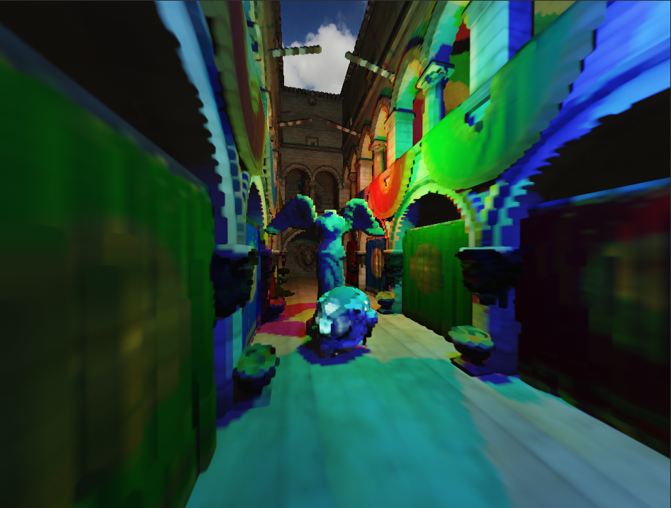
This is a visualization of a 384-sized rgba16f-format 3D texture. It's the output of the voxelization stage. Every pixel/voxel is shaded normally using some basic lighting and classic shadow maps. I only have this single texture, but others might store additional information such as normals for multiple bounces. The voxelization happens using a single shader program. A basic vertex shader and a rather unusal but clever fragment shader.
There are two variables vec3: GridMin, GridMax.
Those define the world space region which the voxel grid spans over. When rendering, triangles get transformed to world space like normally and then mapped from the range [GridMin, GridMax] to [-1, 1] (normalized device coordinates).
Triangles outside the grid will not be voxelized.
As the grid grows, voxel resolution decreases.
#version 460 core
layout(location = 0) in vec3 Position;

uniform vec3 GridMin, GridMax;
out vec3 NormalizedDeviceCoords;

void main() {
    vec3 fragPos = (ModelMatrix * vec4(Position, 1.0)).xyz;

    // transform fragPos from [GridMin, GridMax] to [-1, 1]
    NormalizedDeviceCoords = MapToNdc(fragPos, GridMin, GridMax);

    gl_Position = vec4(NormalizedDeviceCoords, 1.0);
}

vec3 MapToNdc(vec3 value, vec3 rangeMin, vec3 rangeMax) {
    return ((value - rangeMin) / (rangeMax - rangeMin)) * 2.0 - 1.0;
}We won't have any color attachments. In fact there is no FBO at all. We will write into the 3D texture manually using OpenGL image store. Framebuffers are avoided because you can only ever attach a single texture-layer for rendering. Image store works on absolute integer coordinates, so to find the corresponding voxel position we can transform the normalized device coordinates.
#version 460 core
layout(binding = 0, rgba16f) restrict uniform image3D ImgVoxels;

in vec3 NormalizedDeviceCoords;

void main()  {
    vec3 uvw = NormalizedDeviceCoords * 0.5 + 0.5; // transform from [-1, 1] to [0, 1]
    ivec3 voxelPos = ivec3(uvw * imageSize(ImgVoxels)); // transform from [0, 1] to [0, imageSize() - 1]

    vec3 voxelColor = ...; // compute some basic lighting
    imageStore(ImgVoxels, voxelPos, vec4(voxelColor, 1.0));
}
Since we don't have any color or depth attachments we want to use an empty framebuffer. It's used to explicitly communicate OpenGL the render width & height, which normally is derived from the color attachments. To not miss triangles, face culling is off. Color and other writes are turned off implicitly by using the empty framebuffer. Clearing is done by a simple compute shader.
Now, running the voxelization as described so far gives me this. There are two obvious issues that I'll address.
Flickering happens because the world space position for different fragment shader invocations can get mapped to the same voxel, and the invocation that writes to the image at last is random. One decent solution is to store the max() of the already stored and the new voxel color. There are several ways to implement this in a thread-safe manner: Fragment Shader Interlock, CAS-Loop, Atomic Operations.
Fragment Shader Interlock is only available on NVIDIA & Intel. CAS-Loop is what I've seen the most but it's unstable and slow.
So I decided to go with imageAtomicMax.
layout(binding = 0, rgba16f) restrict uniform image3D ImgVoxels;
layout(binding = 1, r32ui) restrict uniform uimage3D ImgVoxelsR;
layout(binding = 2, r32ui) restrict uniform uimage3D ImgVoxelsG;
layout(binding = 3, r32ui) restrict uniform uimage3D ImgVoxelsB;

void main() {
    uvec3 uintVoxelColor = floatBitsToUint(voxelColor);
    imageAtomicMax(ImgVoxelsR, voxelPos, uintVoxelColor.r);
    imageAtomicMax(ImgVoxelsG, voxelPos, uintVoxelColor.g);
    imageAtomicMax(ImgVoxelsB, voxelPos, uintVoxelColor.b);
    imageStore(ImgVoxels, voxelPos, vec4(0.0, 0.0, 0.0, 1.0));
}
Image atomics can only be performed on single channel integer formats, but the voxel texture is required to be at least rgba16f. So I create three additional r32ui-format intermediate textures to perform the atomic operations on. Alpha is just always set to 1.0, no atomic operations needed. After voxelization, in a simple compute shader, they get merged into the final rgba16f texture.
Why are there so many missing voxels? Consider the floor. What do we see if we view it from the side.
Well, there is a thin line, but technically even that shouldn't be visible. When this gets rasterized the voxelization fragment shader won't even run. The camera should have been looking along the Y axis, not Z, because this is the dominant axis that maximizes the amount of projected area (more fragment shader invocations). The voxelization vertex shader doesn't have a view matrix and adding one would be overkill. To make the "camera" look a certain axis we can simply swizzle the vertex positions.
This is typically implemented in a geometry shader by finding the dominant axis of the triangle's geometric normal and then swizzling the vertex positions accordingly. Geometry shaders are known to be very slow, so I went with a different approach.
uniform int RenderAxis; // Set to 0, 1, 2 for each draw

void main() {
    gl_Position = vec4(NormalizedDeviceCoords, 1.0);

    if (RenderAxis == 0) gl_Position = gl_Position.zyxw;
    if (RenderAxis == 1) gl_Position = gl_Position.xzyw;
}
The entire scene simply gets rendered 3 times, once from each axis. No geometry shader is used. This works great together with imageAtomicMax from 2.2 Fixing missing voxels, since the fragment shader doesn't just overwrite a voxel's color each draw.
Performance comparison on 11 million triangles Intel Sponza scene with AMD RX 5700 XT, only measuring the actual voxelization program:
- 5.3 ms without geometry shader (rendering thrice method)
- 10.5 ms with geometry shader (rendering once method)
The rendering thrice method is simpler to implement and faster. Still it's far from optimal. For example swizzling the vertices in a compute shader and then rendering only once, basically emulating the geometry shader, would likely be more performant.
There are certain extensions we can use to improve the voxelization process. These are only supported on NVIDIA GPUs starting from the Maxwell architecture (GTX-900 series).
This extensions is used to improve the implementation discussed in 2.1 Fixing flickering.
It allows to perform atomics on rgba16f-format images. This means the three r32ui-format intermediate textures and the compute shader that merges them into the final voxel texture are no longer needed. Instead we can directly perform imageAtomicMax on the voxel texture.
#version 460 core
#extension GL_NV_shader_atomic_fp16_vector : require
layout(binding = 0, rgba16f) restrict uniform image3D ImgVoxels;

void main() {
    imageAtomicMax(ImgResult, voxelPos, f16vec4(voxelColor, 1.0));
}These extensions are used to improve the implementation discussed in 2.2 Fixing missing voxels
What if the geometry shader wasn't painfully slow? Then we could actually use it instead of rendering the scene 3 times.
Fortunately, GL_NV_geometry_shader_passthrough allows exactly that. The extension limits the abilities of normal geometry shaders, but it lets the hardware implement them with minimal overhead. One limitation is that you can no longer modify vertex positions of the primitive. So how are we going to do per vertex swizzling then? With GL_NV_viewport_swizzle. The extension allows associating a swizzle with a viewport.
#version 460 core
#extension GL_NV_geometry_shader_passthrough : require

layout(triangles) in;
layout(passthrough) in gl_PerVertex {
    vec4 gl_Position;
} gl_in[];

layout(passthrough) in InOutData {
    // in & out variables...
} inData[];

void main() {
    vec3 p1 = gl_in[1].gl_Position.xyz - gl_in[0].gl_Position.xyz;
    vec3 p2 = gl_in[2].gl_Position.xyz - gl_in[0].gl_Position.xyz;
    vec3 normalWeights = abs(cross(p1, p2));

    int dominantAxis = normalWeights.y > normalWeights.x ? 1 : 0;
    dominantAxis = normalWeights.z > normalWeights[dominantAxis] ? 2 : dominantAxis;

    // Swizzle is applied by selecting a viewport
    // This works using the GL_NV_viewport_swizzle extension
    gl_ViewportIndex = 2 - dominantAxis;
}
This is like a standard voxelization geometry shader. It finds the axis from which the triangle should be rendered to maximize projected area and then applies the swizzle accordingly. Except that the swizzle is applied indirectly using GL_NV_viewport_swizzle and the geometry shader is written using GL_NV_geometry_shader_passthrough. How to associate a particular swizzle with a viewport is an exercise left to the reader :).
Voxelization performance for 11 million triangles Intel Sponza at 256^3 resolution, including texture clearing and (potential) merging. Even though the RTX 3050 Ti Laptop is a less powerful GPU we can make it voxelize faster and take up less memory in the process by using the extensions.
| GPU | Baseline | FP16-Atomics(2.5x less memory) | Passthrough-GS | FP16-Atomics(2.5x less memory) + Passthrough-GS |
|---|---|---|---|---|
| RTX 3050 Ti Laptop | 19.05ms | 17.60ms | 6.41ms | 4.93ms |
| RX 5700 XT | 6.49ms | not available | not available | not available |
TODO
There's a surprisingly simple way to do multithreaded texture loading in OpenGL that doesn't require dealing with multiple contexts. With this method you can have your textures gradually load in at run-time without any significant lag.
The technique works like this:
- Get image extends & channels (main thread)
- Allocate "staging buffer" to store pixels (main thread)
- Decode image and copy the pixels into staging buffer (worker thread)
- Transfer pixels from staging buffer into texture (main thread)
You might wonder what Buffer Objects have to do with any of this. They are used because we can upload data to them from any thread by using (persistently) mapped memory. The transfer from buffer into texture happens on the main thread but because the data is already on the GPU it should be pretty fast. Here's an example:
// 1. Allocate buffer to store pixels
var flags = BufferStorageFlags.MapPersistentBit | BufferStorageFlags.MapWriteBit;
GL.CreateBuffers(1, out int stagingBuffer);
GL.NamedBufferStorage(stagingBuffer, imageSize, IntPtr.Zero, flags);

// 2. Upload pixels into buffer
void* bufferMemory = GL.MapNamedBufferRange(stagingBuffer, 0, imageSize, flags);
NativeMemory.Copy(decodedImage, bufferMemory, imageSize);

// 3. Transfer pixels from buffer into texture
GL.BindBuffer(BufferTarget.PixelUnpackBuffer, stagingBuffer);
GL.TextureSubImage2D(___, null);
GL.DeleteBuffer(stagingBuffer);
Decoding the image and copying the pixels into the buffer will be done on a different thread. Notice how the pixels argument in TextureSubImage2D is null. That is because a Pixel Unpack Buffer is bound which is used as the data source. So the argument actually gets interpreted as an offset. By the way, don't worry about the CPU->Buffer->Texture method of uploading adding overhead compared to CPU->Texture. It's what the driver does anyway and it's the default method in Vulkan/DX12.
We need a way to signal to the main thread that it should start step 3 after a worker thread completed step 2. This can be implemented with a Queue.
public static class MainThreadQueue
{
    private static readonly ConcurrentQueue<Action> lazyQueue = new ConcurrentQueue<Action>();

    public static void AddToLazyQueue(Action action)
    {
        lazyQueue.Enqueue(action);
    }

    // Intended to be called periodically from the main thread
    public static void Execute()
    {
        if (lazyQueue.TryDequeue(out Action action))
        {
            action();
        }
    }
}
C# has ConcurrentQueue, which is also thread-safe, so perfect for this use case.
Execute() is called every frame on the main thread. When a worker thread wants something done on the main thread it enqueues the Action and shortly afterwards it will be dequeued and executed. I decided to dequeue only a single Action at a time as I prefer the work to be distributed across multiple frames.
With that done, the final texture loading algorithm is just a couple lines:
int imageSize = imageWidth * imageHeight * imageChannels;

var flags = BufferStorageFlags.MapPersistentBit | BufferStorageFlags.MapWriteBit;
GL.CreateBuffers(1, out int stagingBuffer);
GL.NamedBufferStorage(stagingBuffer, imageSize, IntPtr.Zero, flags);
void* bufferMemory = GL.MapNamedBufferRange(stagingBuffer, 0, imageSize, flags);

Task.Run(() =>
{
    ImageResult imageResult = ImageResult.FromStream(...);
    NativeMemory.Copy(imageResult.Data, bufferMemory, imageSize);

    MainThreadQueue.AddToLazyQueue(() =>
    {
        GL.BindBuffer(BufferTarget.PixelUnpackBuffer, stagingBuffer);
        texture.Upload2D(imageWidth, imageHeight, PixelFormat, PixelType, IntPtr.Zero);
        GL.DeleteBuffer(stagingBuffer);
    });
});
The algorithm requires knowing the image extends and channels before it is decoded in order to compute the number of bytes to allocate for the buffer. If you are using stbi, the stbi_info family of functions can give you that information.
The code sits in the model loader, but I like to wrap it inside an other MainThreadQueue.AddToLazyQueue() so that loading only really starts as soon as the render loop is entered and MainThreadQueue.Execute() gets called.
Creating a thread for every image might introduce lag so I am calling Task.Run() which uses a thread pool.
Finally, a nice way to demonstrate that things are working is to have a random thread sleep inside the worker threads, causing textures to slowly load in at different times.
Variable Rate Shading is when you render different regions of the framebuffer at different resolutions. This feature is exposed in OpenGL through the NV_shading_rate_image extension. When drawing the hardware fetches a "Shading Rate Image" looks up the value in a user defined shading rate palette and applies that shading rate to the block of fragments.
So all we need to do is generate this Shading Rate Image which is really just a r8ui-format texture where each pixel covers
a 16x16 tile of the framebuffer. This image will control the resolution at which each tile is rendered.
Example of a generated Shading Rate Image while the camera is rapidly moving forward, taking into account velocity and variance of luminance
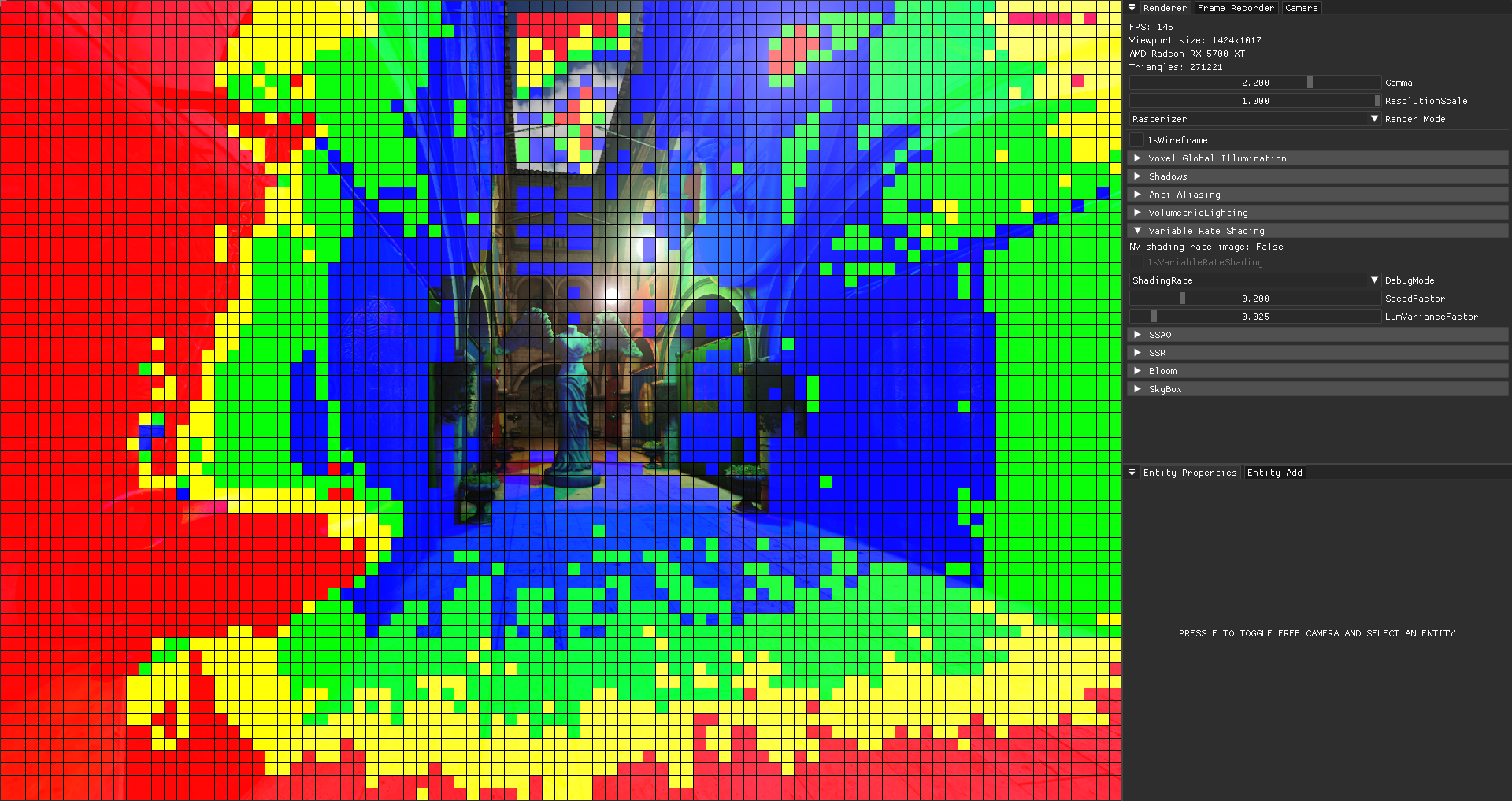
Red stands for 1 invocation per 4x4 pixels which means 16x less fragment shader invocations in those regions. No color is the default - 1 invocation per pixel.
The ultimate goal of the algorithm should be to apply a as low as possible shading rate without the user noticing. I assume the following are cases where we can safely reduce the shading rate:
- High average magnitude of velocity
- Low variance of luminance
This makes sense as you can generally see less detail in fast moving things. And if the luminance is roughly the same across a tile (which is what the variance tells you) there is not much detail to begin with.
In both cases we need the average of some value over all 256 pixels.
Average is defined as:
Where
For starters you could call atomicAdd(SharedMem, value * (1.0 / n)) on shared memory, but atomics on floats is not a core feature and, as far as my testing goes, the following approach was no slower:
#define TILE_SIZE 16
layout(local_size_x = TILE_SIZE, local_size_y = TILE_SIZE, local_size_z = 1) in;

const float AVG_MULTIPLIER = 1.0 / (TILE_SIZE * TILE_SIZE);
shared float Average[TILE_SIZE * TILE_SIZE];

void main() {
    Average[gl_LocalInvocationIndex] = GetSpeed() * AVG_MULTIPLIER;

    for (int cutoff = (TILE_SIZE * TILE_SIZE) / 2; cutoff > 0; cutoff /= 2) {
        if (gl_LocalInvocationIndex < cutoff) {
            Average[gl_LocalInvocationIndex] += Average[cutoff + gl_LocalInvocationIndex];
        }
        barrier();
    }
    // average is computed and stored in Average[0]
}
This algorithm first loads all the values we want to average into shared memory. Then it adds the first half of array entries to the other half, storing results in the first half. After that, all the new values are again divided and added together. The output is now 1/4 the size of the original array. At some point, the final sum is collapsed into the first element.
That's it for the averaging part.
Calculating the variance requires a little more work. What we actually want is the Coefficient of variation (CV), because that is normalized and independent of scale (e.g {5, 10} and {10, 20} have same CV = ~0.33). But the two are related - variance is needed to compute CV.
The CV equals standard deviation divided by the average. And standard deviation is just the square root of variance.
Here is an implementation. I put the parallel adding stuff from above in the function ParallelSum.
#define TILE_SIZE 16
layout(local_size_x = TILE_SIZE, local_size_y = TILE_SIZE, local_size_z = 1) in;

const float AVG_MULTIPLIER = 1.0 / (TILE_SIZE * TILE_SIZE);

void main() {
    float pixelLuminance = GetLuminance();

    float tileAvgLuminance = ParallelSum(pixelLuminance * AVG_MULTIPLIER);
    float tileLuminanceVariance = ParallelSum(pow(pixelLuminance - tileAvgLuminance, 2.0) * AVG_MULTIPLIER);

    if (gl_LocalInvocationIndex == 0) {
        float stdDev = sqrt(tileLuminanceVariance);
        float coeffOfVariation = stdDev / tileAvgLuminance;

        // use coeffOfVariation as a measure of "how different are the luminance values to each other"
    }
}
At this point, you can use both the average speed and the Coefficient of variation of the luminance to get an appropriate shading rate. That is not the most interesting part. I decided to scale both of these factors, add them together and then use that to mix between different rates.
While operating on shared memory is fast, Subgroup Intrinsics are faster.
They are a relatively new topic on its own and you almost never see them mentioned in the context of OpenGL. The subgroup is an implementation dependent set of invocations in which data can be shared efficiently. There are many subgroup operations. The whole thing is document here, but vendor specific/arb extensions with ARB_shader_group_vote actually being part of core also exist.
Anyway, the one that is particularly interesting for our case of computing a sum is KHR_shader_subgroup_arithmetic, or more specifically the subgroupAdd function.
On my GPU a subgroup is 32 invocations big.
When I call subgroupAdd(2) the function will return 64.
So it does a sum over all values passed to the function in the scope of all (active) subgroup invocations.
Using this knowledge, my optimized version of a workgroup wide sum looks like this:
#define SUBGROUP_SIZE __subroupSize__
#extension GL_KHR_shader_subgroup_arithmetic : require

layout(local_size_x = 256, local_size_y = 1, local_size_z = 1) in;

shared float SharedSums[gl_WorkGroupSize.x / SUBGROUP_SIZE];
void main() {
    float subgroupSum = subgroupAdd(GetValueToAdd());

    // single invocation of the subgroup should write result
    // into shared mem for further workgroup wide processing
    if (subgroupElect()) {
        SharedSums[gl_SubgroupID] = subgroupSum;
    }
    barrier();

    // finally add up all sums previously computed by the subgroups in this workgroup
    for (int cutoff = gl_NumSubgroups / 2; cutoff > 0; cutoff /= 2) {
        if (gl_LocalInvocationIndex < cutoff) {
            SharedSums[gl_LocalInvocationIndex] += SharedSums[cutoff + gl_LocalInvocationIndex];
        }
        barrier();
    }

    // average is computed and stored in SharedSums[0]
}
Note how the workgroup expands the size of a subgroup, so we still have to use shared memory to obtain a workgroup wide result.
However in the for loop it now only has to iterate through log2(gl_NumSubgroups / 2) values instead of log2(gl_WorkGroupSize.x / 2).
In core OpenGL, geometry shaders are the only stage where you can write to gl_Layer. This variable specifies which layer of the framebuffer attachment to render to.
There is a common approach to point shadow rendering where instead of:
for (int face = 0; face < 6; face++) {
    NamedFramebufferTextureLayer(fbo, attachment, cubemap, level, face);
    // Render Scene into <face>th face of cubemap
    RenderScene();
}
you do:
RenderScene();void main() {
for (int face = 0; face < 6; face++) {
gl_Layer = face;
OutputTriangle();
}
}Notice how instead of calling NamedFramebufferTextureLayer from the CPU we set gl_Layer inside a geometry shader saving us 5 draw calls and driver overhead.
So this should be faster right? - No. Geometry shaders are known to have a huge performance penalty on both AMD and NVIDIA. I don't have any measurements now, but I implemented both and simply doing 6 draw calls was way faster than the geometry shader method on RX 5700 XT. However we can do better. There are multiple extensions which allow you to set gl_Layer from the vertex shader!
ARB_shader_viewport_layer_array for example reads:
In order to use any viewport or attachment layer other than zero, a geometry shader must be present. Geometry shaders introduce processing overhead and potential performance issues. The AMD_vertex_shader_layer and AMD_vertex_shader_viewport_index extensions allowed the gl_Layer and gl_ViewportIndex outputs to be written directly from the vertex shader with no geometry shader present. This extension effectively merges ...
Using any of these extensions, the way you do single-draw-call point shadow rendering might look like this:
RenderSceneInstanced(count: 6);#extension GL_ARB_shader_viewport_layer_array : enable
#extension GL_AMD_vertex_shader_layer : enable
#extension GL_NV_viewport_array2 : enable
#define HAS_VERTEX_LAYERED_RENDERING (GL_ARB_shader_viewport_layer_array || GL_AMD_vertex_shader_layer || GL_NV_viewport_array2)
void main() {
#if HAS_VERTEX_LAYERED_RENDERING
gl_Layer = gl_InstanceID;
gl_Position = PointShadow.FaceMatrices[gl_Layer] * Positon;
#else
// fallback
#endif
}Since vertex shaders can't generate vertices like geometry shaders, instanced rendering is used to tell OpenGL to render every vertex 6 times (once for each face). Inside the shader we can then use gl_InstanceID as the face to render to.
It gets a bit more complicated when you also support actual instancing or culling, but the idea stays the same.
Just want to mention that OpenGL provides useful shadow sampler types like samplerCubeShadow or sampler2DShadow.
When using shadow samplers, texture lookup functions accept an additional parameter with which the depth value in the texture
is compared. The returned value is no longer the depth value, but instead a visibility ratio in the range of [0, 1].
When using linear filtering the comparison is evaluated and averaged for a 2x2 block of pixels.
And all that in one function!
To configure a texture such that it can be sampled by a shadow sampler, you can do this:
GL.TextureParameter(texture, TextureParameterName.TextureCompareMode, (int)TextureCompareMode.CompareRefToTexture);
GL.TextureParameter(texture, TextureParameterName.TextureCompareFunc, (int)All.Less);
And sample it in glsl like that:
layout(binding = 0) uniform samplerCubeShadow ShadowTexture;

void main() {
    float fragDepth = GetDepthRange0_1();
    float visibility = texture(ShadowTexture, vec4(coords, fragDepth));
}
Here is a comparison of using shadow samplers (right) vs not using them.
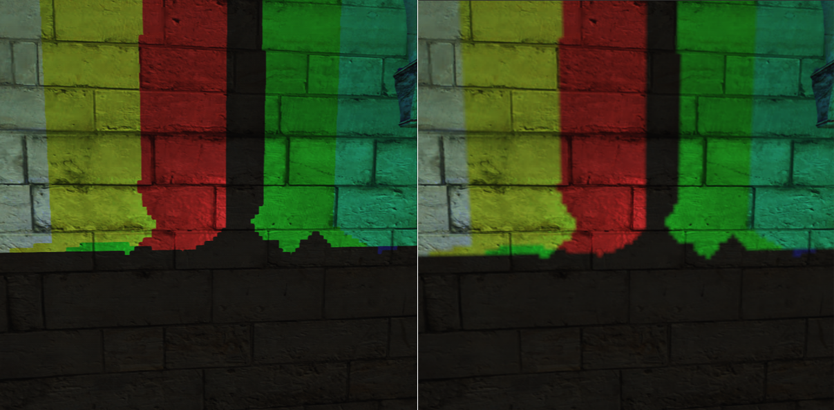
Of course, you can combine this with software filtering like PCF to get even better results.
All Multi Draw Indirects internally just call another non multi draw command drawcount times.
In the case of MultiDrawElementsIndirect this underyling draw call is DrawElementsInstancedBaseVertexBaseInstance.
This effectively allows multiple meshes to be drawn with one API call, reducing driver overhead.
Arguments for these underlying draw calls are provided by us and expected to have the following format:
struct DrawElementsCmd
{
    int Count; // indices count
    int InstanceCount; // number of instances
    int FirstIndex; // offset in indices array
    int BaseVertex; // offset in vertex array
    int BaseInstance; // sets the value of `gl_BaseInstance`. Only used by the API when doing old school instancing
}
The DrawCommands are not supplied through the draw function itself as usual, but have to be put into a buffer (hence "Indirect" suffix) which is then bound
to GL_DRAW_INDIRECT_BUFFER before drawing.
So to render 5 meshes you'd have to configure 5 DrawCommand and load them into the said buffer.
The final draw could then be as simple as:
public void Draw()
{
    GL.BindVertexArray(vao); // contains merged vertex and indices array + vertex format
    GL.BindBuffer(BufferTarget.DrawIndirectBuffer, drawCommandBuffer); // contains DrawCommand[Meshes.Length]

    GL.MultiDrawElementsIndirect(PrimitiveType.Triangles, DrawElementsType.UnsignedInt, IntPtr.Zero, Meshes.Length, 0);
}
While this renders all geometry just fine, you might be wondering how to access the entirety of materials to compute proper shading. After all scenes like Sponza come with a lot of textures and the usual method of manually declaring sampler2D in glsl quickly becomes insufficient as we can't do state changes between draw calls anymore (which is good) to swap out materials. This is where Bindless Textures comes in.
First of all ARB_bindless_texture is not a core extension. Nevertheless, almost all AMD and NVIDIA GPUs implement it, as you can see here. Unfortunately RenderDoc doesn't support it.
The main idea behind Bindless Textures is the ability to generate a unique 64 bit handle from any texture, which can then be used to uniquely identify it inside GLSL. This means that you no longer have to call BindTextureUnit (or the older ActiveTexture + BindTexture) to bind a texture to a texture unit.
Instead, generate the handle and somehow communicate it to the GPU in what ever way you like (commonly through a SSBO).
Example:
ulong handle = GL.Arb.GetTextureHandle(texture);
GL.Arb.MakeTextureHandleResident(handle);

GL.CreateBuffers(1, out int buffer);
GL.NamedBufferStorage(buffer, sizeof(ulong), handle, BufferStorageFlags.DynamicStorageBit);
GL.BindBufferBase(BufferRangeTarget.ShaderStorageBuffer, 0, buffer);
#version 460 core
#extension GL_ARB_bindless_texture : require
layout(std430, binding = 0) restrict readonly buffer TextureSSBO {
sampler2D Textures[];
} textureSSBO;
void main() {
sampler2D myTexture = textureSSBO.Textures[0];
vec4 color = texture(myTexture, coords);
}Here we generate a handle, upload it into a buffer and then access it through a shader storage block which exposes the buffer to the shader.
After the handle is generated, the texture's state is immutable. This cannot be undone.
To sample a bindless texture it's handle must also be made resident.
The extension allows you to place sampler2D directly inside the shader storage block as shown. Note however that you could also do uvec2 Textures[]; and then perform a cast like: sampler2D myTexture = sampler2D(textureSSBO.Textures[0]).
In the case of an MDI renderer as described in 1.0 Multi Draw Indirect. the process of fetching each mesh's texture would look something like this:
#version 460 core
#extension GL_ARB_bindless_texture : require

layout(std430, binding = 0) restrict readonly buffer MaterialSSBO {
    Material Materials[];
} materialSSBO;

layout(std430, binding = 1) restrict readonly buffer MeshSSBO {
    Mesh Meshes[];
} meshSSBO;

void main() {
    Mesh mesh = meshSSBO.Meshes[gl_DrawID];
    Material material = materialSSBO.Materials[mesh.MaterialIndex];

    vec4 albedo = texture(material.Albedo, coords);
}
gl_DrawID is in the range of [0, drawcount - 1] and identifies the current sub draw inside a multi draw. And each sub draw corresponds to a mesh.
Material is just a struct containing one or more bindless textures.
There is one caveat (not exclusive to bindless textures), which is that they must be indexed with a dynamically uniform expression. Fortunately gl_DrawID is defined to satisfy this requirement.
Frustum culling is the process of identifying objects outside a camera frustum and then avoiding unnecessary computations for them. The following implementation fits perfectly into the whole GPU driven rendering thing.
The ingredients needed to get started are:
- A projection + view matrix
- Buffer containing each mesh's model matrix
- Buffer containing each mesh's draw command
- Buffer containing each mesh's bounding box
In an MDI renderer as described in 1.0 Multi Draw Indirect, the first three points are required anyway. And getting a local space bounding box from each mesh's vertices shouldn't be a problem.
Remember how MultiDrawElementsIndirect reads draw commands from a buffer object?
That means the GPU can modify it's own drawing parameters by writing into this buffer object (using shader storage blocks).
And that's the key to GPU accelerated frustum culling without any CPU readback.
Basically, the CPU side of things is as simple this:
void Render()
{
    // Frustum Culling
    GL.UseProgram(frustumCullingProgram);
    GL.DispatchCompute((Meshes.Length + 64 - 1) / 64, 1, 1);
    GL.MemoryBarrier(MemoryBarrierFlags.CommandBarrierBit);

    // Drawing
    GL.BindVertexArray(vao);
    GL.UseProgram(drawingProgram);
    GL.BindBuffer(BufferTarget.DrawIndirectBuffer, drawCommandBuffer);
    GL.MultiDrawElementsIndirect(PrimitiveType.Triangles, DrawElementsType.UnsignedInt, IntPtr.Zero, Meshes.Length, 0);
}
A compute shader is dispatched to do the culling and adjust the content of drawCommandBuffer accordingly.
The memory barrier ensures that at the point where MultiDrawElementsIndirect reads from drawCommandBuffer all previous
incoherent writes into to that buffer are visible.
Let's get to the culling shader:
#version 460 core
layout(local_size_x = 64, local_size_y = 1, local_size_z = 1) in;

struct DrawElementsCmd {
    uint Count;
    uint InstanceCount;
    uint FirstIndex;
    uint BaseVertex;
    uint BaseInstance;
};

layout(std430, binding = 0) restrict writeonly buffer DrawCommandsSSBO {
    DrawCommand DrawCommands[];
} drawCommandSSBO;

void main() {
    uint meshIndex = gl_GlobalInvocationID.x;
    if (meshIndex >= meshSSBO.Meshes.length())
        return;

    Mesh mesh = meshSSBO.Meshes[meshIndex];
    Box box = mesh.AABB;

    Frustum frustum = GetFrustum(ProjView * mesh.ModelMatrix);
    bool isMeshInFrustum = FrustumBoxIntersect(frustum, node.Min, node.Max);

    drawCommandSSBO.DrawCommands[meshIndex].InstanceCount = isMeshInFrustum ? 1 : 0;
}
Each thread grabs a mesh builds a frustum and then compares it against the aabb.
drawCommandSSBO stores the draw commands used by MultiDrawElementsIndirect.
If the test fails, InstanceCount is set to 0 otherwise 1.
A mesh with InstanceCount = 0 will not cause any vertex shader invocations later when things are drawn, saving a lot of computations.
