博客链接:SSAO
项目地址:Graphic-researcher/UnityCrytekSponza-master2019 (github.com)
环境光遮蔽(AO:Ambient Occlusion) 模拟光线与物体的遮挡关系,SS即Screen Space,指利用屏幕空间信息(像素深度、法线等缓冲)实现物体在间接光下的阴影。
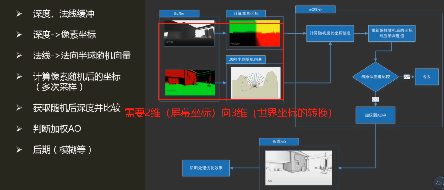
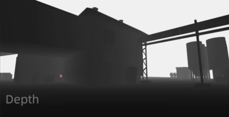
深度缓冲:重构相机(观察)空间中坐标(Z)重构该视点下三维场景
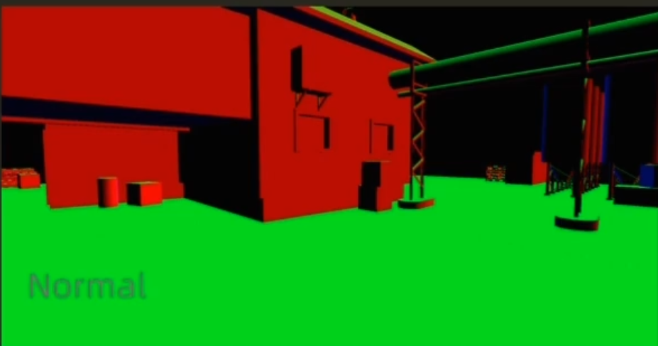
法线缓冲:重构每像素“法线-切线-副法线”构成的坐标轴,用以计算法线半球采样的随机向量(描述该像素AO强度)
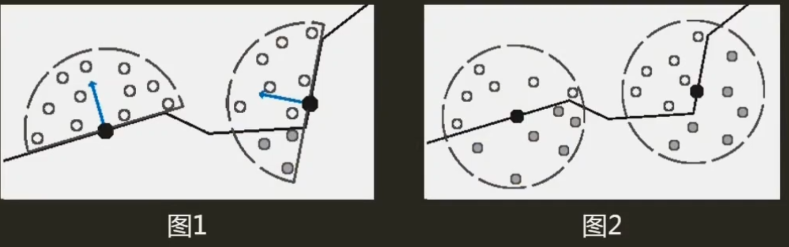
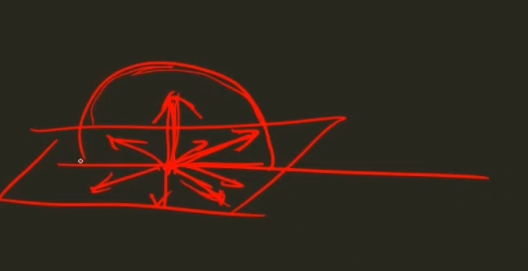
法向半球
黑:当前计算样本 蓝:样本法向量 白、灰:采样点(灰色:被遮挡点,深度大于周围,据此判断最终AO强度)
若为全球形采样会导致墙面遮挡强度过高,因为样本周围一半采样点都在表面下(被遮挡)
C#:
//获取深度&法线缓存数据
private void Start()
{
    cam = this.GetComponent<Camera>();
    //相机渲染模式为带深度和法线
    cam.depthTextureMode = cam.depthTextureMode | DepthTextureMode.DepthNormals;
}
shader:
//获取深度法线图
sampler2D _CameraDepthNormalsTexture;

//...other code

//采样获得深度值和法线值
float3 viewNormal;
float linear01Depth;
float4 depthnormal = tex2D(_CameraDepthNormalsTexture, i.uv); //uv属于屏幕空间(当前渲染图像)
DecodeDepthNormal(depthnormal, linear01Depth, viewNormal);    //解码数据,获取采样后深度值和法线值

//...other code

inline void DecodeDepthNormal( float4 enc, out float depth, out float3 normal )//in UnityCG.cginc
{
    depth = DecodeFloatRG (enc.zw);
    normal = DecodeViewNormalStereo (enc);
}从NDC(标准化设备坐标)空间重建
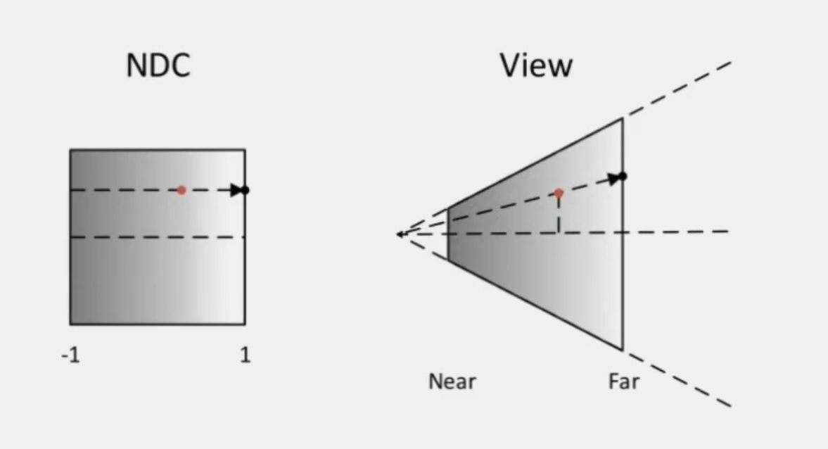
//step1:计算样本屏幕坐标 vertex shader
float4 screenPos = ComputeScreenPos(o.vertex);//屏幕纹理坐标
//step2: 转换至NDC空间 vertex shader
float4 ndcPos = (screenPos / screenPos.w) * 2 - 1;// NDC position
//step3: 计算相机空间中至远屏幕方向 vertex shader
float3 clipVec = float3(ndcPos.x, ndcPos.y, 1.0) * _ProjectionParams.z; //_ProjectionParams.z -> 相机远平面
//step4:矩阵变换至相机空间中样本相对相机的方向
o.viewVec = mul(unity_CameraInvProjection, clipVec.xyzz).xyz;
//step5:重建相机空间样本坐标 fragment shader
float3 viewPos = linear01Depth * i.viewVec;//获取像素相机屏幕坐标位置

/*
屏幕空间->NDC空间->裁剪空间-逆投影矩阵->观察(相机)空间
*/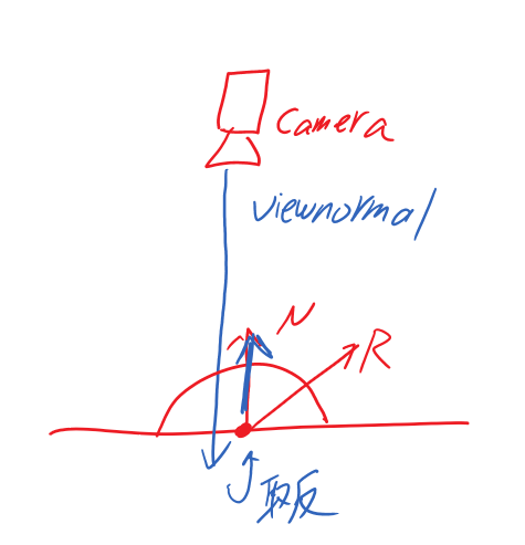
//Step1 设置法向量
//获取像素相机屏幕法线,法相z方向相对于相机为负(所以 需要乘以-1置反),并处理成单位向量
viewNormal = normalize(viewNormal) * float3(1, 1, -1);
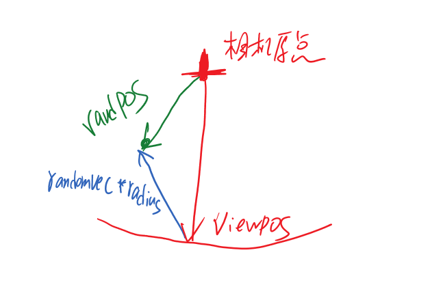
//Step2 randvec法线半球的随机向量(用于构建随机的正交基,而非所有样本正交基一致),此处先设置为统一变量(后面优化会改成随机)
float3 randvec = normalize(float3(1,1,1));
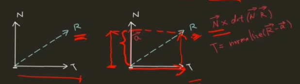
//Step3 求切向量 利用函数cross叉积求负切向量
/*
Gramm-Schimidt处理创建正交基
法线&切线&副切线构成的坐标空间
*/
float3 tangent = normalize(randvec - viewNormal * dot(randvec, viewNormal));
float3 bitangent = cross(viewNormal, tangent);
float3x3 TBN = float3x3(tangent, bitangent, viewNormal);关于TBN: 切线空间(TBN) ---- 聊聊图形学中的矩阵运算 unity入门精要4.7 法线变换
C# 生成随机样本
private void GenerateAOSampleKernel()
{
//...other code...
    for (int i = 0; i < SampleKernelCount; i++) //在此生成随机样本
    {
        var vec = new Vector4(Random.Range(-1.0f, 1.0f), Random.Range(-1.0f, 1.0f), Random.Range(0, 1.0f), 1.0f);
        vec.Normalize();
        var scale = (float)i / SampleKernelCount;
        //使分布符合二次方程的曲线
        scale = Mathf.Lerp(0.01f, 1.0f, scale * scale);
        vec *= scale;
        sampleKernelList.Add(vec);
    }
}
shader 比较法线半球中样本深度与观察点深度以确定AO强度
for (int i = 0; i < sampleCount; i++)
{
//随机向量,转化至法线切线空间中 得到此法线半球的随机向量
float3 randomVec = mul(_SampleKernelArray[i].xyz, TBN);
//ao权重
float weight = smoothstep(0, 0.2, length(randomVec.xy));
//计算随机法线半球后的向量
float3 randomPos = viewPos + randomVec * _SampleKeneralRadius;
//转换到屏幕坐标
float3 rclipPos = mul((float3x3)unity_CameraProjection, randomPos);
float2 rscreenPos = (rclipPos.xy / rclipPos.z) * 0.5 + 0.5;
/*
观察(相机)空间->-投影矩阵->裁剪空间->屏幕空间
*/
float randomDepth;
float3 randomNormal;
float4 rcdn = tex2D(_CameraDepthNormalsTexture, rscreenPos);
DecodeDepthNormal(rcdn, randomDepth, randomNormal);
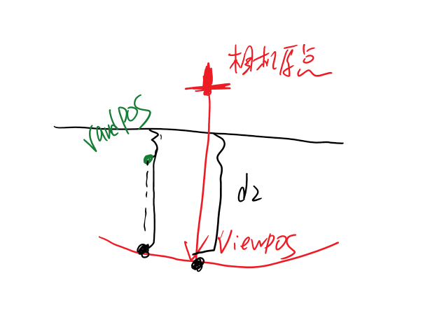
//判断累加ao值
//采样点的深度值和样本深度比对前后关系
//ao += (randomDepth>=linear01Depth)?1.0:0.0;//是否有遮挡关//老师这里可能笔误了
ao += (randomDepth>=linear01Depth)?0.0:1.0;//是否有遮挡关系
}
当前版本shader:
//https://blog.csdn.net/tianhai110/article/details/5684128?utm_medium=distribute.pc_relevant.none-task-blog-BlogCommendFromMachineLearnPai2-7.channel_param&depth_1-utm_source=distribute.pc_relevant.none-task-blog-BlogCommendFromMachineLearnPai2-7.channel_param
Shader "ImageEffect/SSAO0"
{
    Properties
    {
        [HideInInspector]_MainTex ("Texture", 2D) = "white" {}
    }

	CGINCLUDE
    #include "UnityCG.cginc"
	struct appdata
    {
        float4 vertex : POSITION;
        float2 uv : TEXCOORD0;
    };

    struct v2f
    {
        float2 uv : TEXCOORD0;
        float4 vertex : SV_POSITION;
		float3 viewVec : TEXCOORD1;
		float3 viewRay : TEXCOORD2;
    };

	#define MAX_SAMPLE_KERNEL_COUNT 64

	float3 _randomVec;
	bool _isRandom;

	sampler2D _MainTex;
	//获取深度法线图
	sampler2D _CameraDepthNormalsTexture;

	//Ao
	sampler2D _NoiseTex;
	float4 _SampleKernelArray[MAX_SAMPLE_KERNEL_COUNT];
	float _SampleKernelCount;
	float _SampleKeneralRadius;
	float _DepthBiasValue;
	float _RangeStrength;
	float _AOStrength;
    v2f vert_Ao (appdata v)
    {
        v2f o;
        o.vertex = UnityObjectToClipPos(v.vertex);
        o.uv = v.uv;

		//计算相机空间中的像素方向(相机到像素的方向)
		//https://zhuanlan.zhihu.com/p/92315967
		//屏幕纹理坐标
		float4 screenPos = ComputeScreenPos(o.vertex);
		// NDC position 转换至NDC空间
		float4 ndcPos = (screenPos / screenPos.w) * 2 - 1;
		// 计算至远屏幕方向
		float3 clipVec = float3(ndcPos.x, ndcPos.y, 1.0) * _ProjectionParams.z;//_ProjectionParams.z -> 相机远平面
		//矩阵变换至相机空间中样本相对相机的方向
		o.viewVec = mul(unity_CameraInvProjection, clipVec.xyzz).xyz;

		/*
		屏幕空间->NDC空间->裁剪空间-逆投影矩阵->观察(相机)空间
		*/
        return o;
    }

	//Ao计算
    fixed4 frag_Ao (v2f i) : SV_Target
    {
        //采样屏幕纹理
        fixed4 col = tex2D(_MainTex, i.uv);

		//采样获得深度值和法线值
		float3 viewNormal;
		float linear01Depth;
		float4 depthnormal = tex2D(_CameraDepthNormalsTexture,i.uv);//uv属于屏幕空间(当前渲染图像)
		DecodeDepthNormal(depthnormal,linear01Depth,viewNormal);//解码数据,获取采样后深度值和法线值

		//获取像素相机屏幕坐标位置
		float3 viewPos = linear01Depth * i.viewVec;

		//获取像素相机屏幕法线,法相z方向相对于相机为负(所以 需要乘以-1置反),并处理成单位向量
		viewNormal = normalize(viewNormal) * float3(1, 1, -1);

		//铺平纹理
		float2 noiseScale = _ScreenParams.xy / 4.0;
		float2 noiseUV = i.uv * noiseScale;
		float3 randvec = normalize(float3(1,1,1));
		//randvec法线半球的随机向量
		if(_isRandom)
			randvec = normalize(_randomVec);
		else
			randvec = tex2D(_NoiseTex,noiseUV).xyz;
		//float3 randvec = normalize(float3(1,1,1));
		//float3 randvec = tex2D(_NoiseTex,noiseUV).xyz;
		//Gramm-Schimidt处理创建正交基
		//法线&切线&副切线构成的坐标空间
		float3 tangent = normalize(randvec - viewNormal * dot(randvec,viewNormal));//求切向量
		float3 bitangent = cross(viewNormal,tangent);//利用函数cross叉积求负切向量
		float3x3 TBN = float3x3(tangent,bitangent,viewNormal);

		//采样核心
		float ao = 0;
		int sampleCount = _SampleKernelCount;//每个像素点上的采样次数
		//https://blog.csdn.net/qq_39300235/article/details/102460405
		for(int i=0;i<sampleCount;i++){
			//随机向量,转化至法线切线空间中 得到此法线半球(TBN空间)的随机向量
			float3 randomVec = mul(_SampleKernelArray[i].xyz,TBN);

			//ao权重
			float weight = smoothstep(0,0.2,length(randomVec.xy));

			//计算随机法线半球后的向量
			float3 randomPos = viewPos + randomVec * _SampleKeneralRadius;
			//转换到屏幕坐标
			float3 rclipPos = mul((float3x3)unity_CameraProjection, randomPos);
			float2 rscreenPos = (rclipPos.xy / rclipPos.z) * 0.5 + 0.5;

			float randomDepth;
			float3 randomNormal;
			float4 rcdn = tex2D(_CameraDepthNormalsTexture, rscreenPos);
            //随机样本在屏幕的深度和法线信息
			DecodeDepthNormal(rcdn, randomDepth, randomNormal);

			//判断累加ao值
			//采样点的深度值和样本深度比对前后关系
			ao += (randomDepth>=linear01Depth)?1.0:0.0;
		}

		ao = ao/sampleCount;
		return float4(ao,ao,ao,1);
    }

	//应用AO贴图

	sampler2D _AOTex;

	fixed4 frag_Composite(v2f i) : SV_Target
	{
		fixed4 col = tex2D(_MainTex, i.uv);
		fixed4 ao = tex2D(_AOTex, i.uv);
		col.rgb *= ao.r;
		return col;
	}

	ENDCG

    SubShader
    {
		Cull Off ZWrite Off ZTest Always

		//Pass 0 : Generate AO
		Pass
        {
            CGPROGRAM
            #pragma vertex vert_Ao
            #pragma fragment frag_Ao
            ENDCG
        }
        //Pass 1 : Composite AO
		Pass
		{
			CGPROGRAM
			#pragma vertex vert_Ao
			#pragma fragment frag_Composite
			ENDCG
		}
    }
}(randomDepth>=linear01Depth)?1.0:0.0

如下视频,更改随机向量,会看到遮挡关系随之变化
如下视频,更改采样点数量以及采样半径,遮挡关系的变化,采样的样本越多越好,但是采样半径需要适中,过小效果不明显,过大又过于强烈
上述算法基本概况了SSAO算法的情况,但还有很多优化空间。
首先,我们的随机向量固定太死,结果可能会很生硬,所以我们可以对噪声贴图采样以增加正交基随机性
//铺平纹理
float2 noiseScale = _ScreenParams.xy / 4.0;
float2 noiseUV = i.uv * noiseScale;
float3 randvec = normalize(float3(1,1,1));
randvec = tex2D(_NoiseTex,noiseUV).xyz;
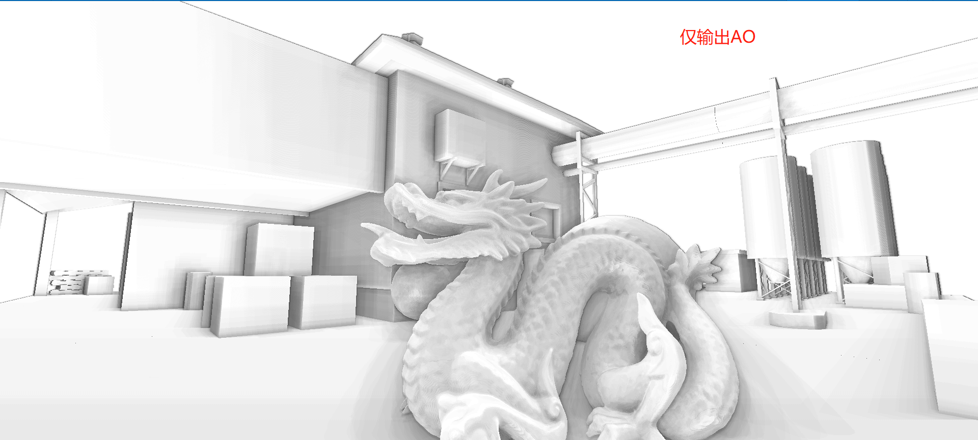
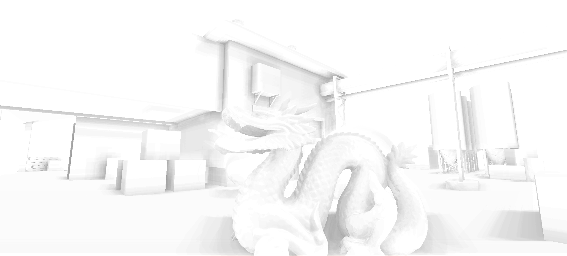
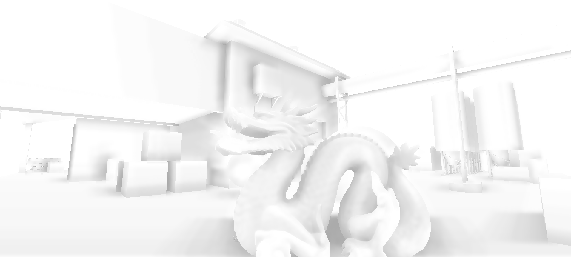
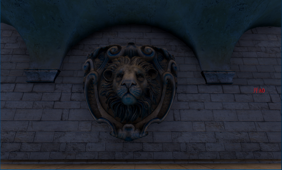
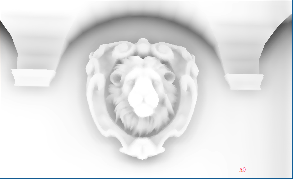
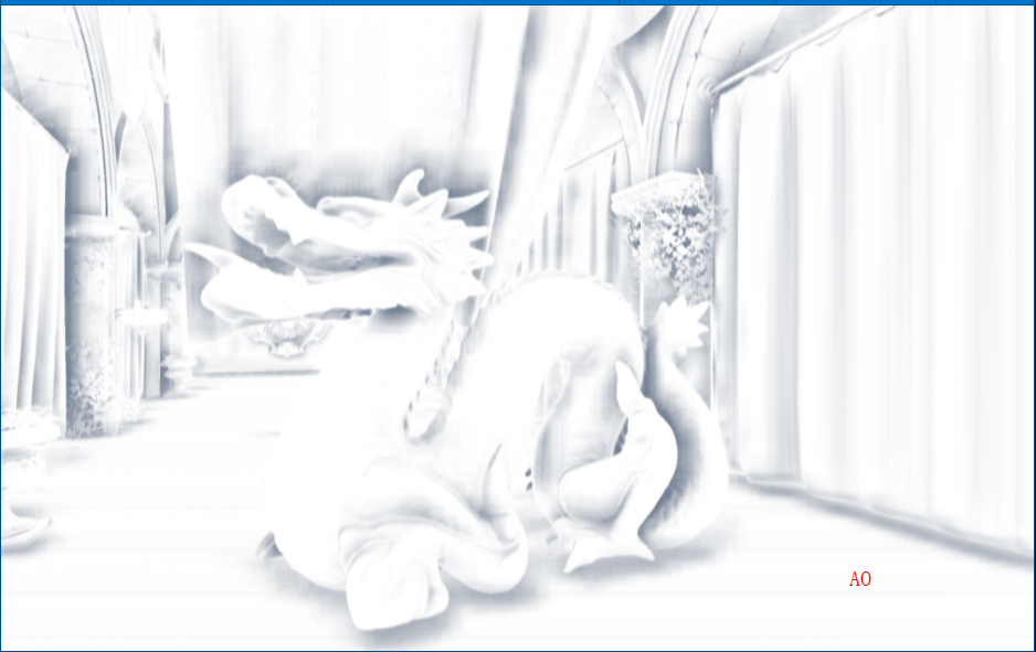
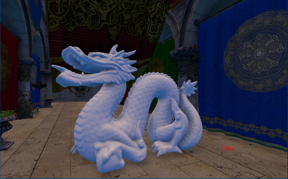
如下图,在AO图中,天空和屋顶形成遮蔽关系,而这种情况不符合现实
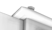
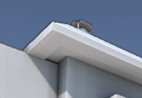
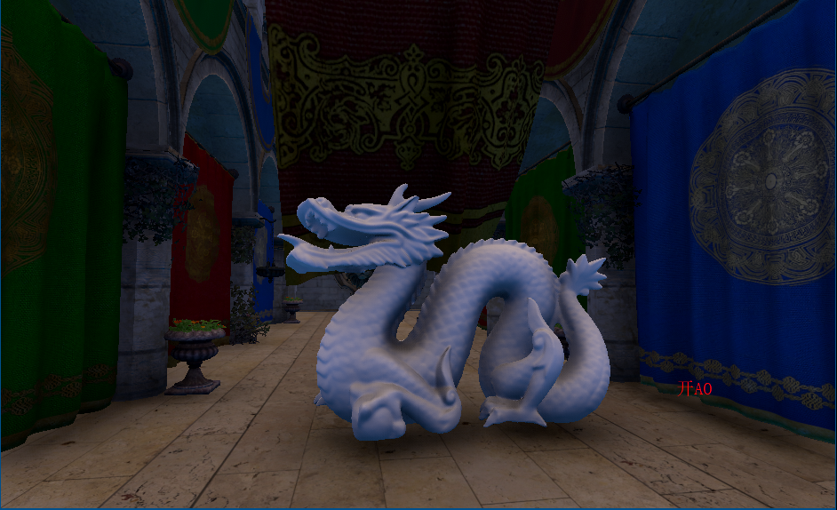
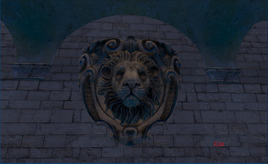
原因是如果随机样本在屏幕上对应为背景(天空)区域,深度值和当前着色点相差很大,可能会导致错误的遮挡关系,再看下图,龙不该挡住远处的建筑,这也是SSAO经典问题
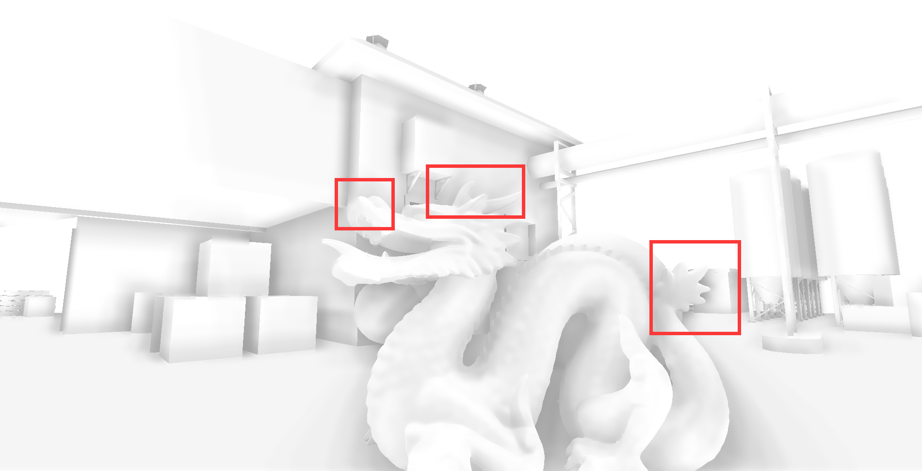
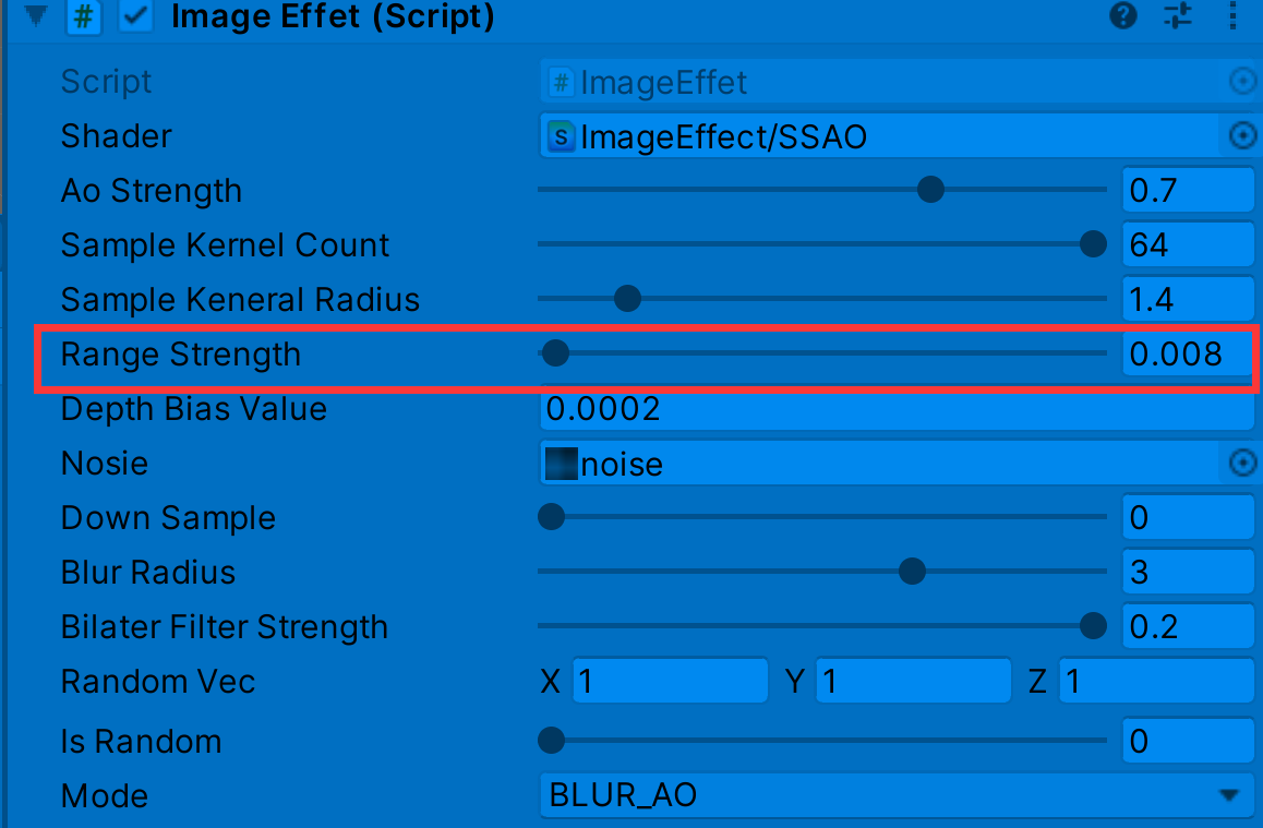
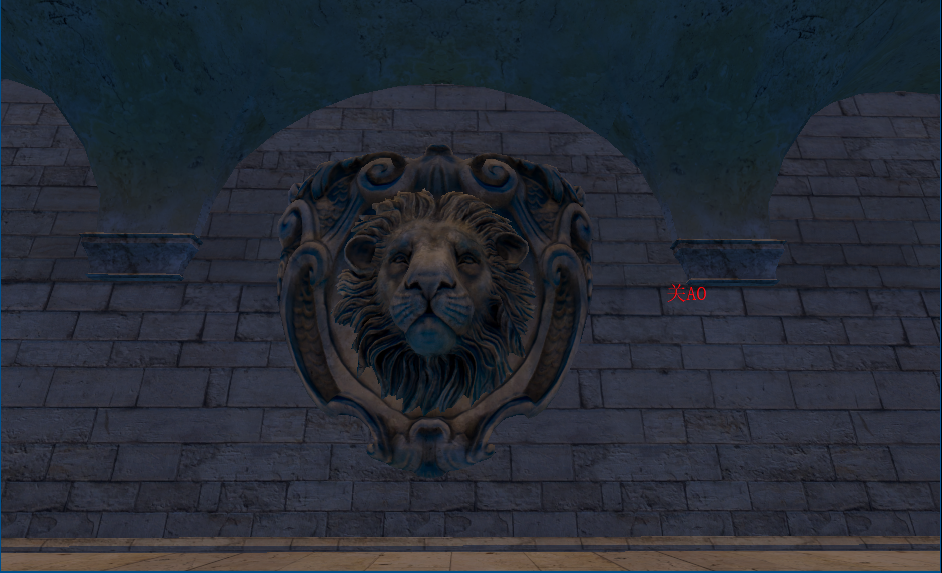
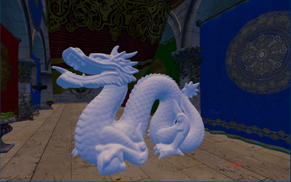
float range = abs(randomDepth - linear01Depth) > _RangeStrength ? 0.0 : 1.0;//解决深度差过大(模型边界)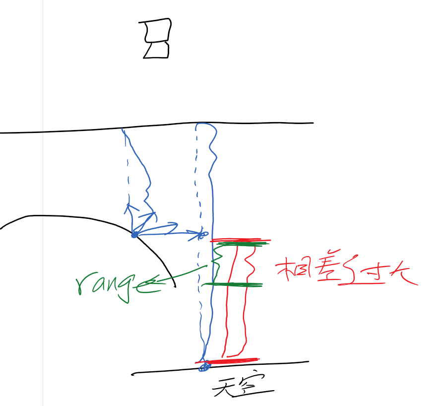
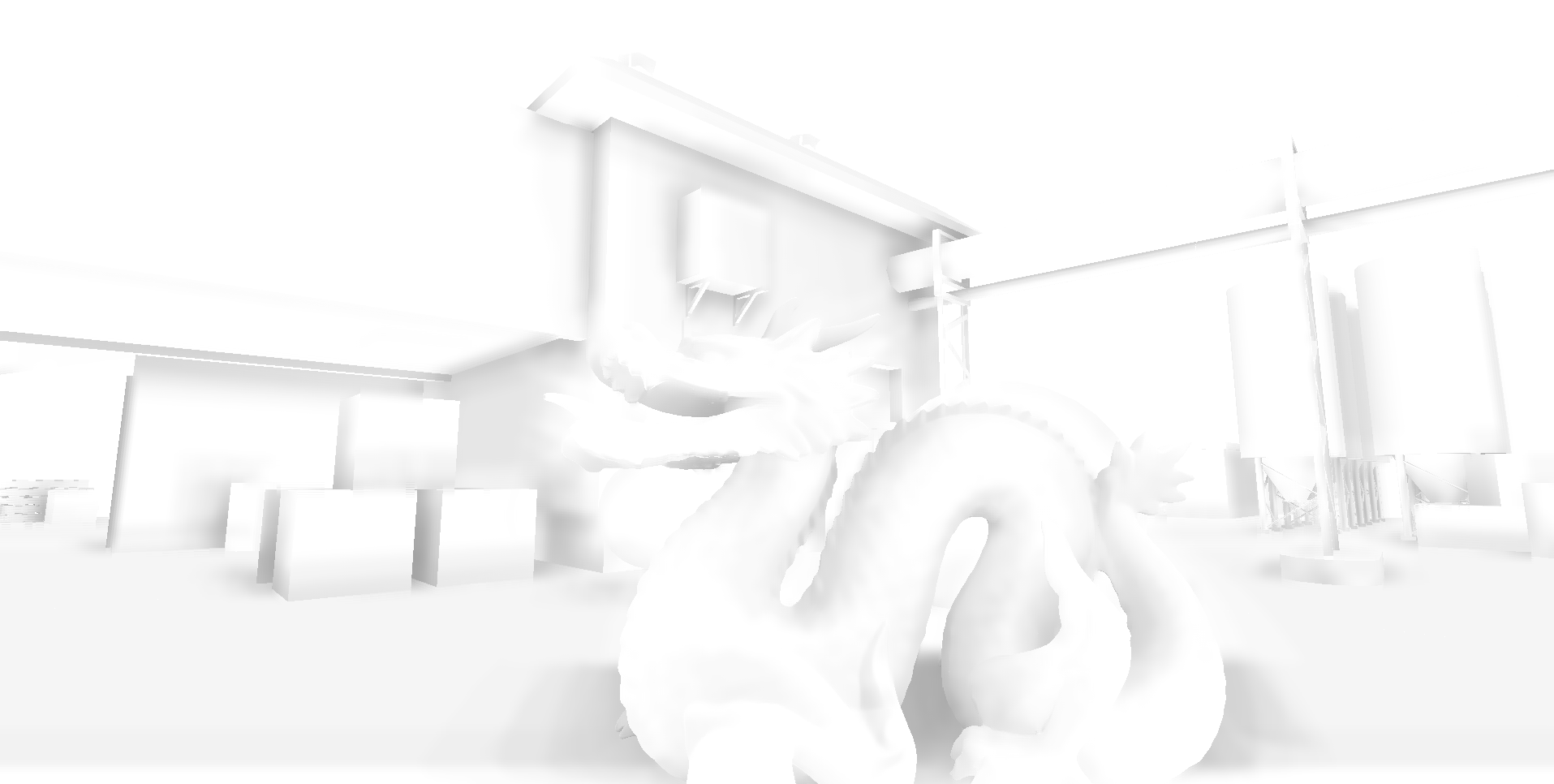
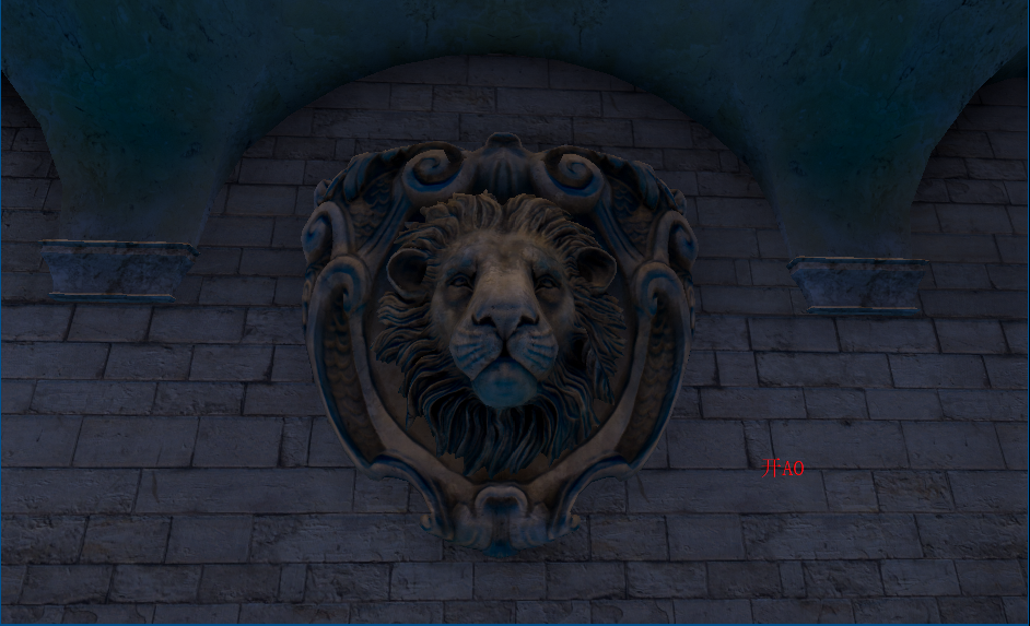
此时模型边缘阴影问题缓解了
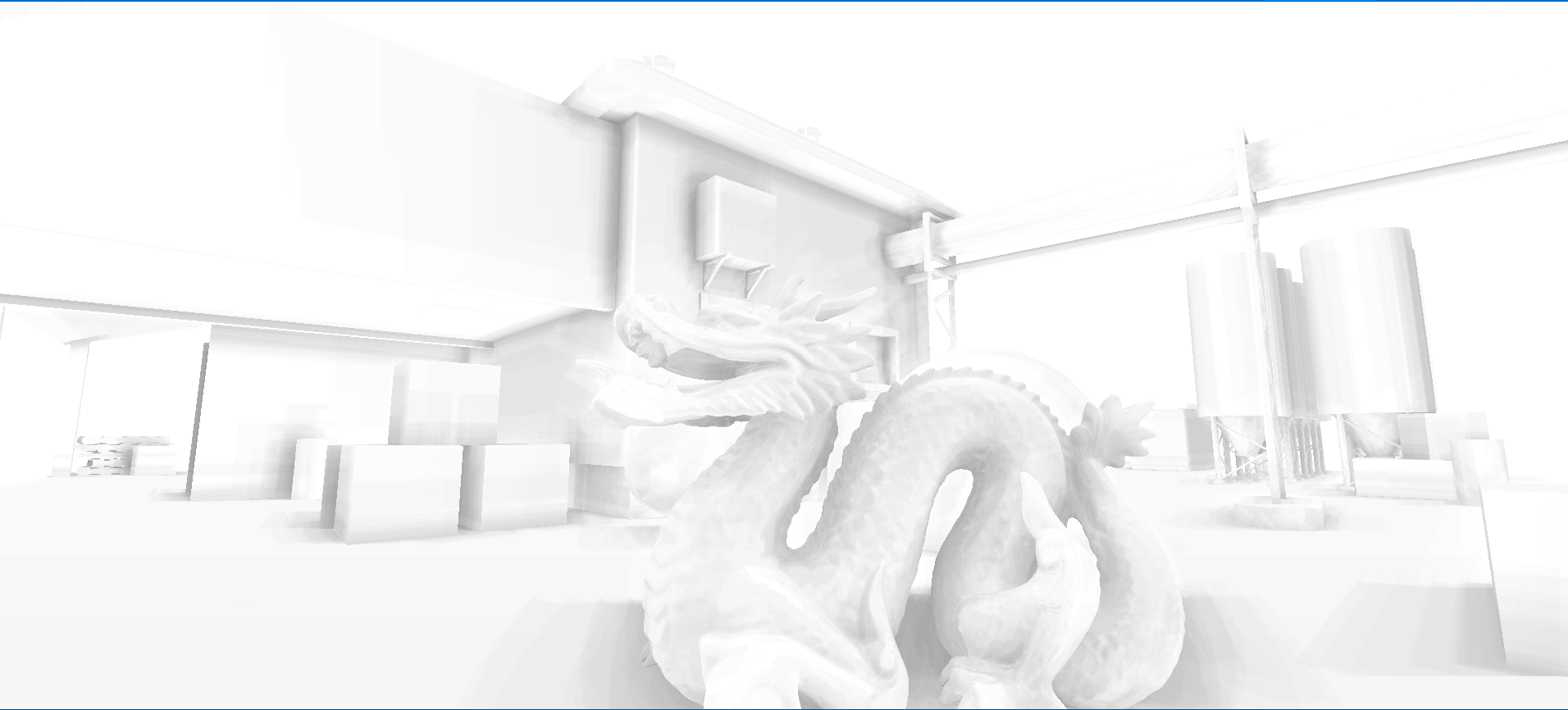
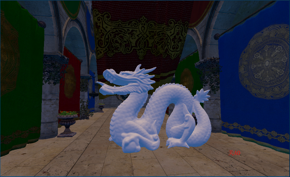
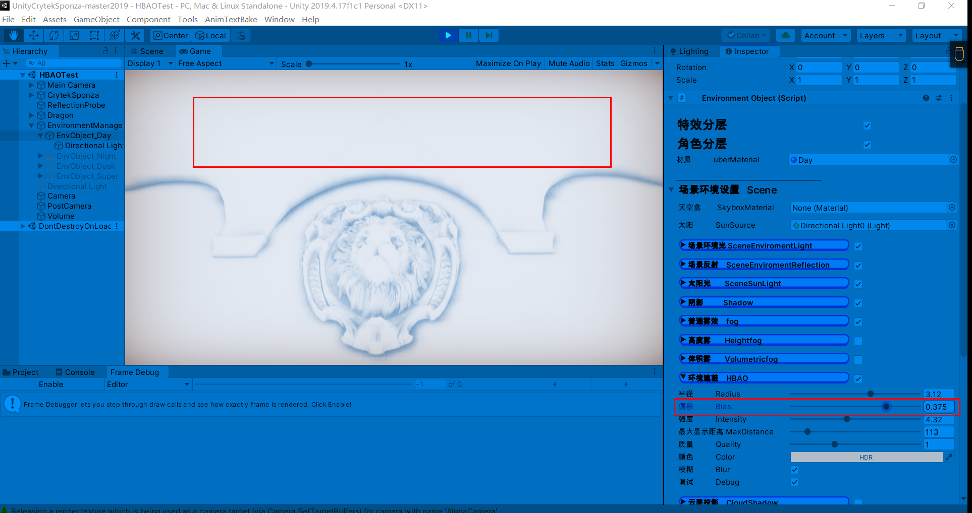
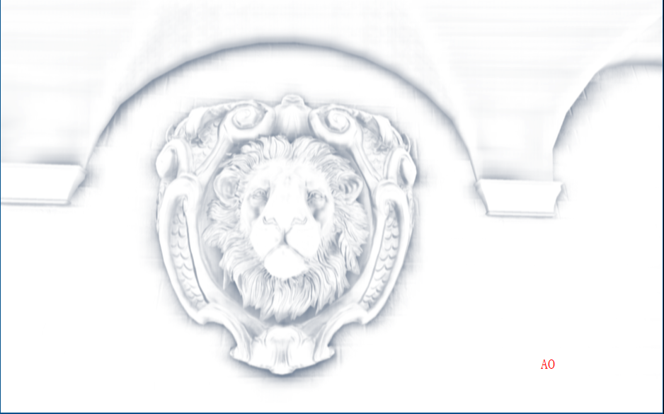
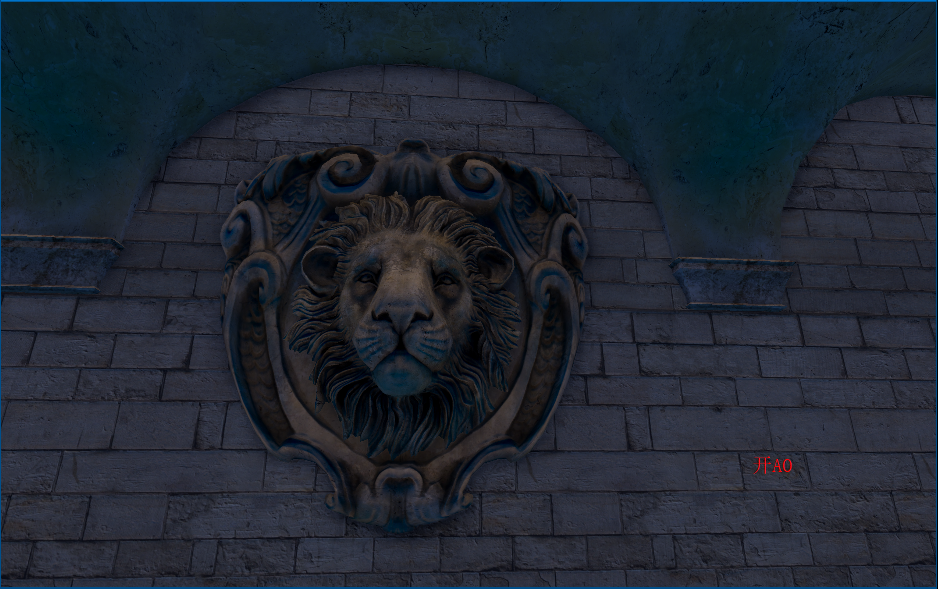
上图我们发现在一些墙面上出现了阴影,而同一平面不会有遮挡关系,这是由于随机点深度值和着色点深度很近,我们可以增加深度偏移
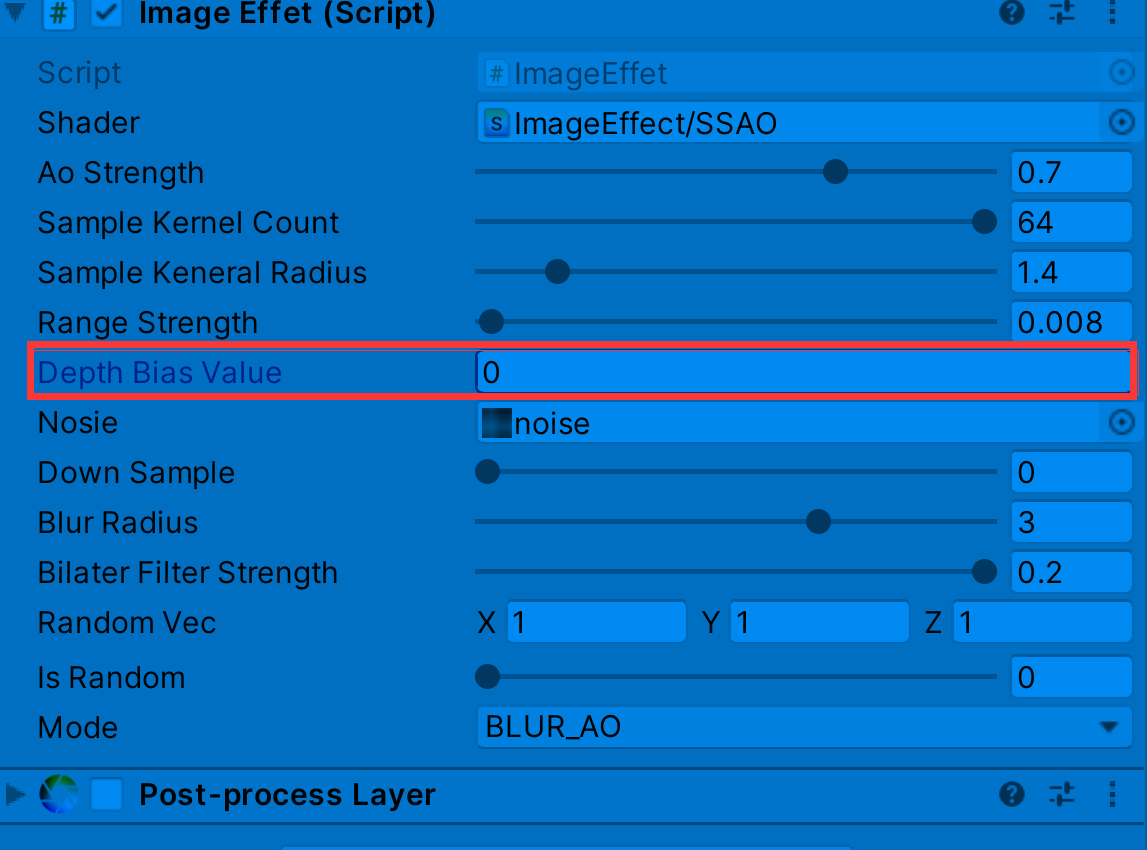
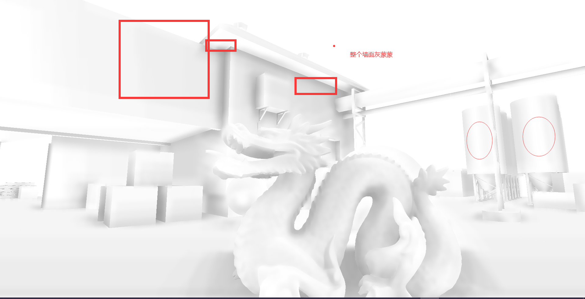
float selfCheck = randomDepth + _DepthBiasValue < linear01Depth ? 1.0 : 0.0;//解决自阴影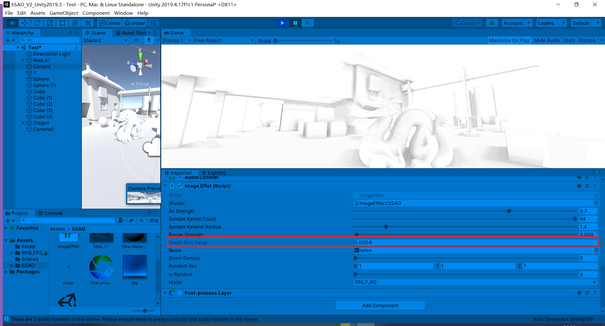

深度值的把控也是一种取舍,如上较大的偏移虽然解决部分墙面自阴影问题,但龙上的遮蔽细节大打折扣
//ao权重
float weight = smoothstep(0,0.2,length(randomVec.xy));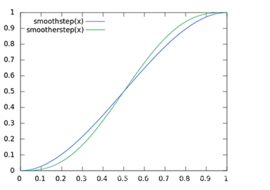
双边滤波或其他滤波方式
	fixed4 frag_Blur (v2f i) : SV_Target
	{
		//_MainTex_TexelSize -> https://forum.unity.com/threads/_maintex_texelsize-whats-the-meaning.110278/
		float2 delta = _MainTex_TexelSize.xy * _BlurRadius.xy;

		float2 uv = i.uv;
		float2 uv0a = i.uv - delta;
		float2 uv0b = i.uv + delta;
		float2 uv1a = i.uv - 2.0 * delta;
		float2 uv1b = i.uv + 2.0 * delta;
		float2 uv2a = i.uv - 3.0 * delta;
		float2 uv2b = i.uv + 3.0 * delta;

		float3 normal = GetNormal(uv);
		float3 normal0a = GetNormal(uv0a);
		float3 normal0b = GetNormal(uv0b);
		float3 normal1a = GetNormal(uv1a);
		float3 normal1b = GetNormal(uv1b);
		float3 normal2a = GetNormal(uv2a);
		float3 normal2b = GetNormal(uv2b);

		fixed4 col = tex2D(_MainTex, uv);
		fixed4 col0a = tex2D(_MainTex, uv0a);
		fixed4 col0b = tex2D(_MainTex, uv0b);
		fixed4 col1a = tex2D(_MainTex, uv1a);
		fixed4 col1b = tex2D(_MainTex, uv1b);
		fixed4 col2a = tex2D(_MainTex, uv2a);
		fixed4 col2b = tex2D(_MainTex, uv2b);

		half w = 0.37004405286;
		half w0a = CompareNormal(normal, normal0a) * 0.31718061674;
		half w0b = CompareNormal(normal, normal0b) * 0.31718061674;
		half w1a = CompareNormal(normal, normal1a) * 0.19823788546;
		half w1b = CompareNormal(normal, normal1b) * 0.19823788546;
		half w2a = CompareNormal(normal, normal2a) * 0.11453744493;
		half w2b = CompareNormal(normal, normal2b) * 0.11453744493;

		half3 result;
		result = w * col.rgb;
		result += w0a * col0a.rgb;
		result += w0b * col0b.rgb;
		result += w1a * col1a.rgb;
		result += w1b * col1b.rgb;
		result += w2a * col2a.rgb;
		result += w2b * col2b.rgb;

		result /= w + w0a + w0b + w1a + w1b + w2a + w2b;
		return fixed4(result, 1.0);
	}
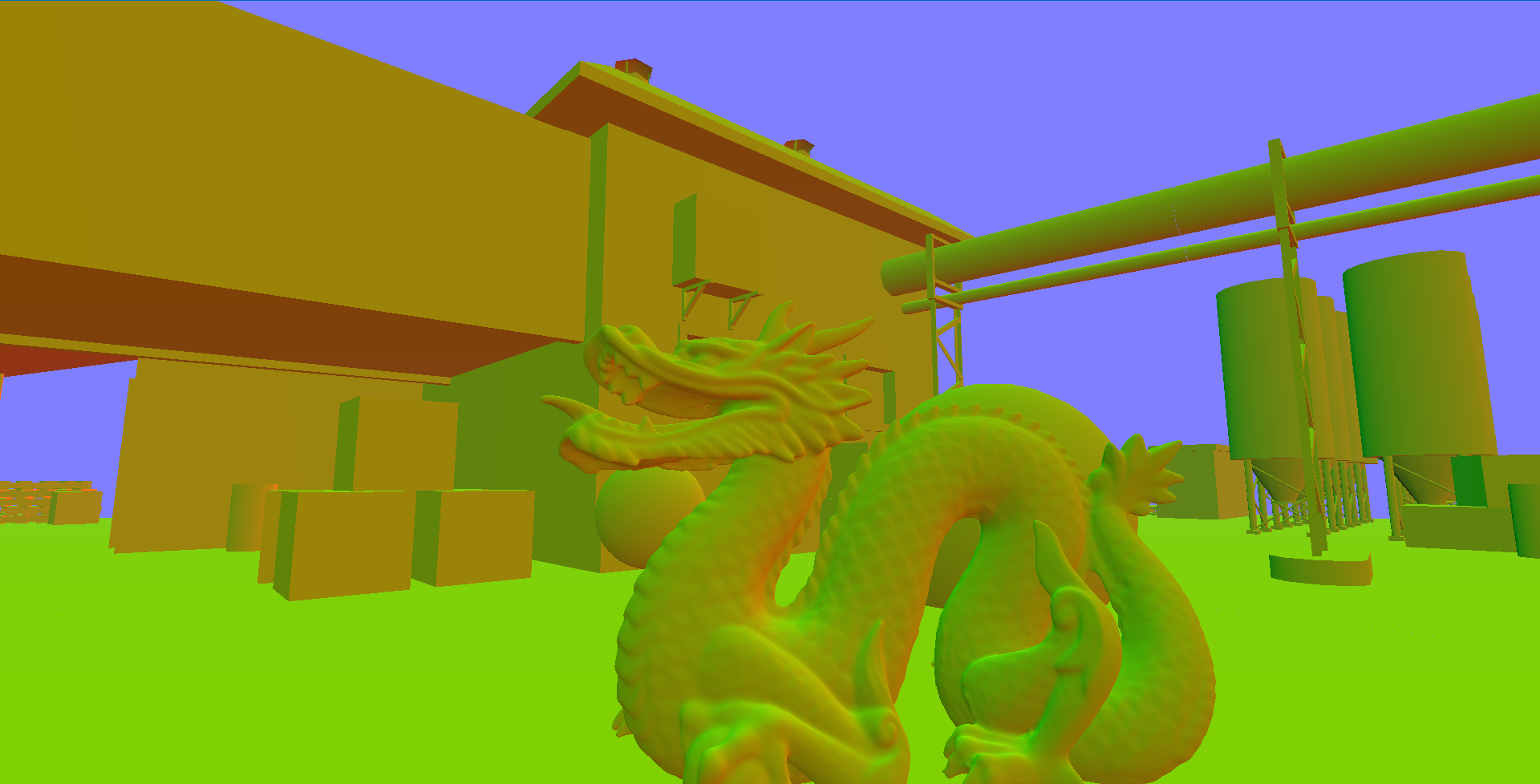
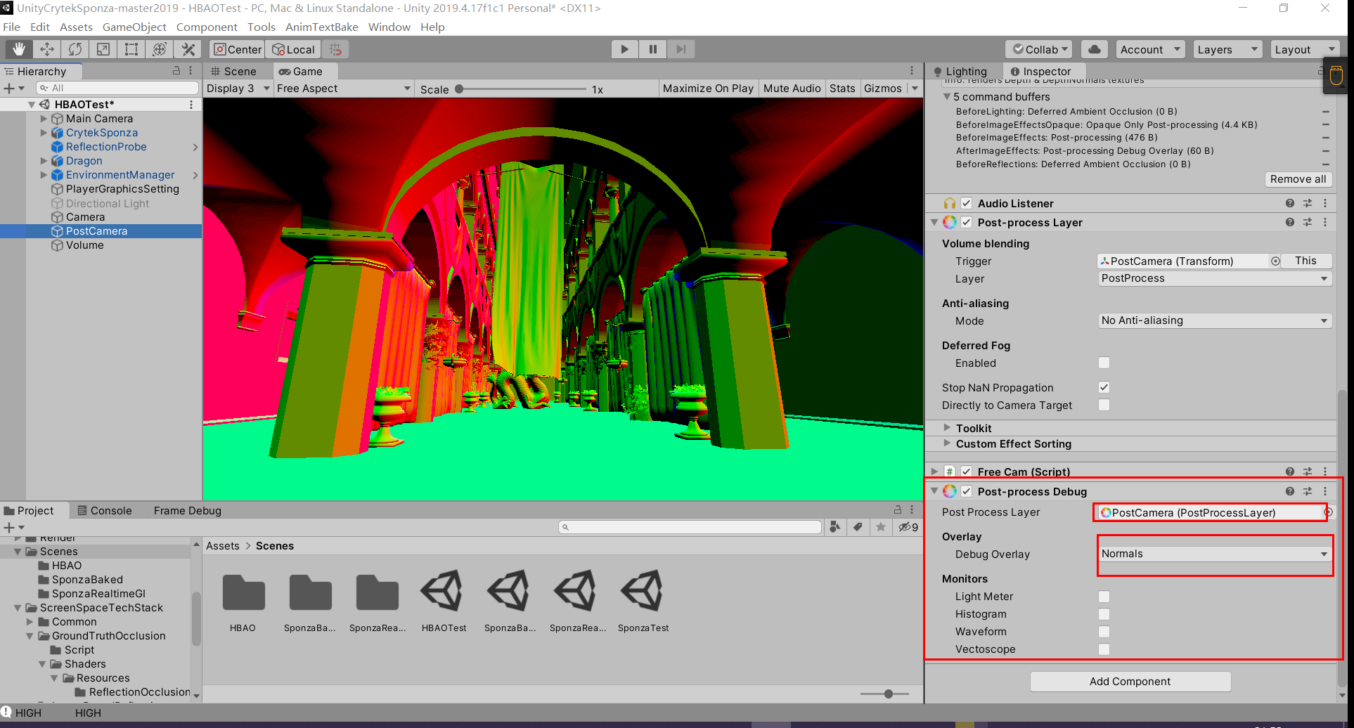
法线
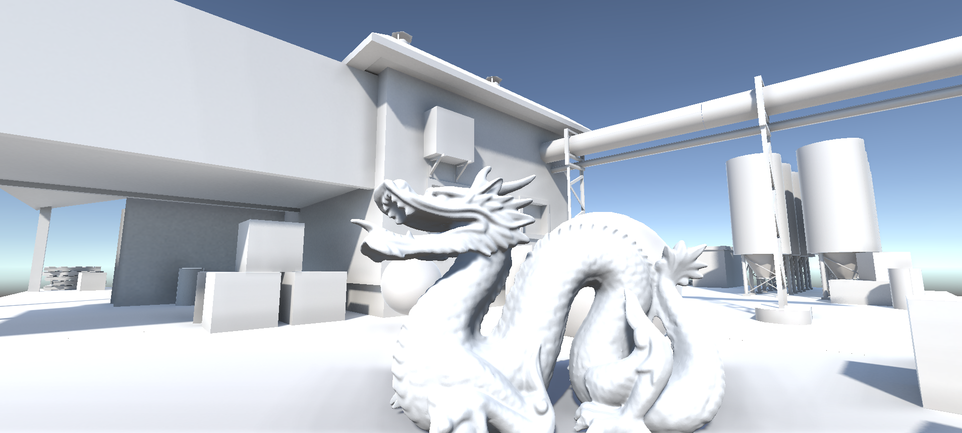
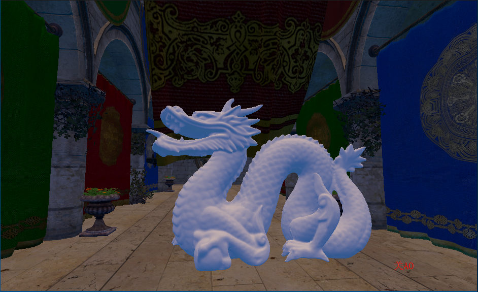
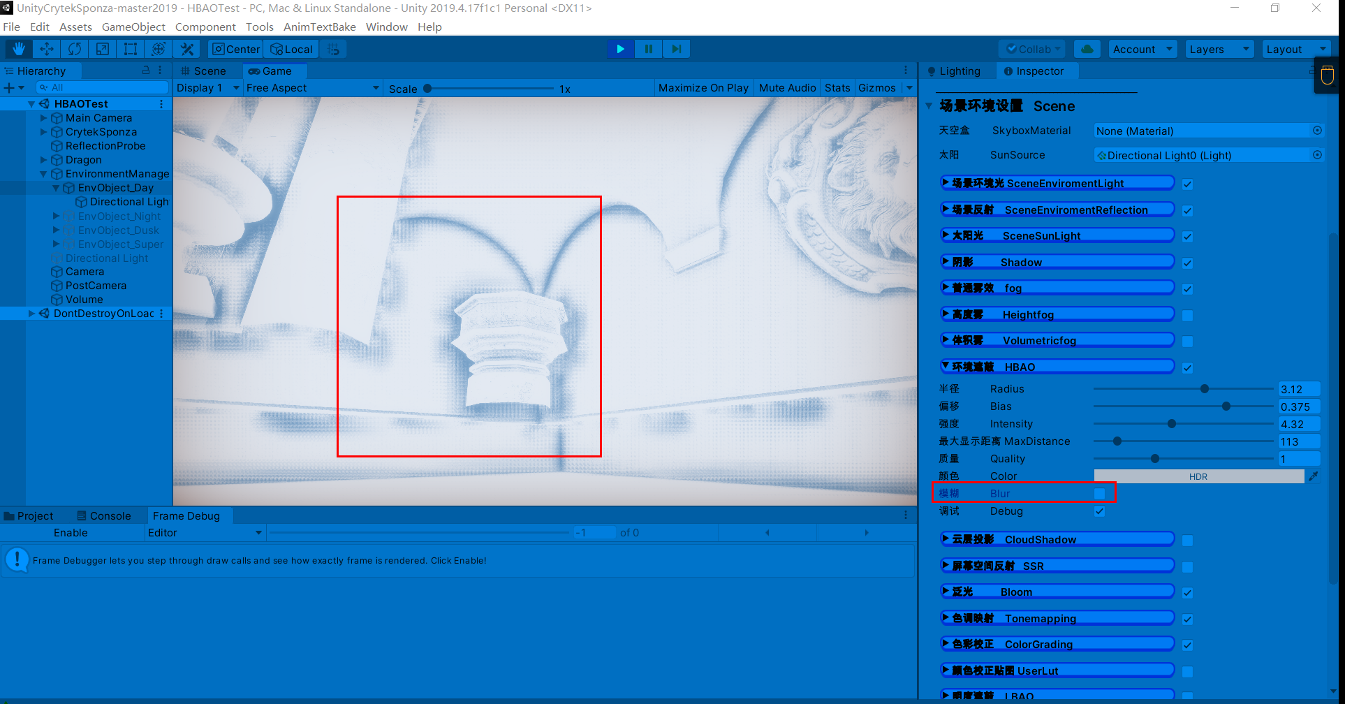
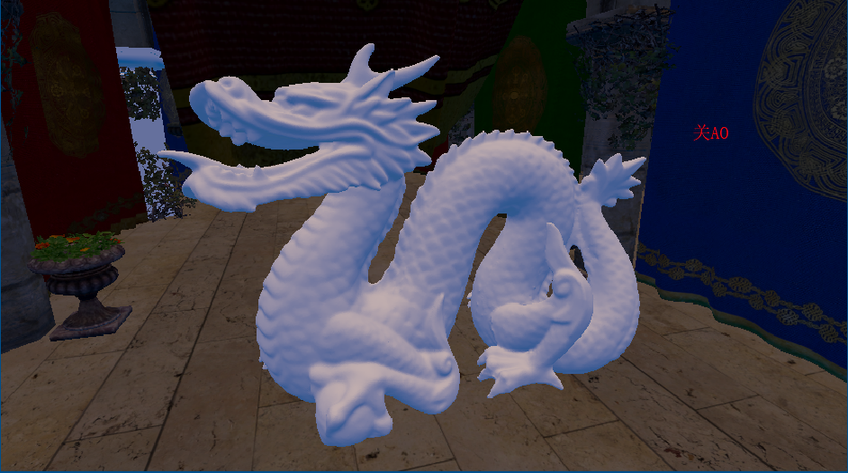
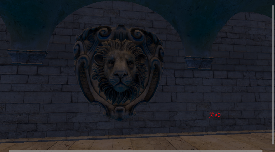
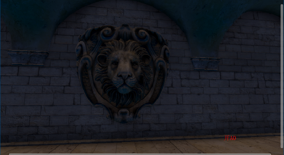
关闭SSAO(包含lightmap)
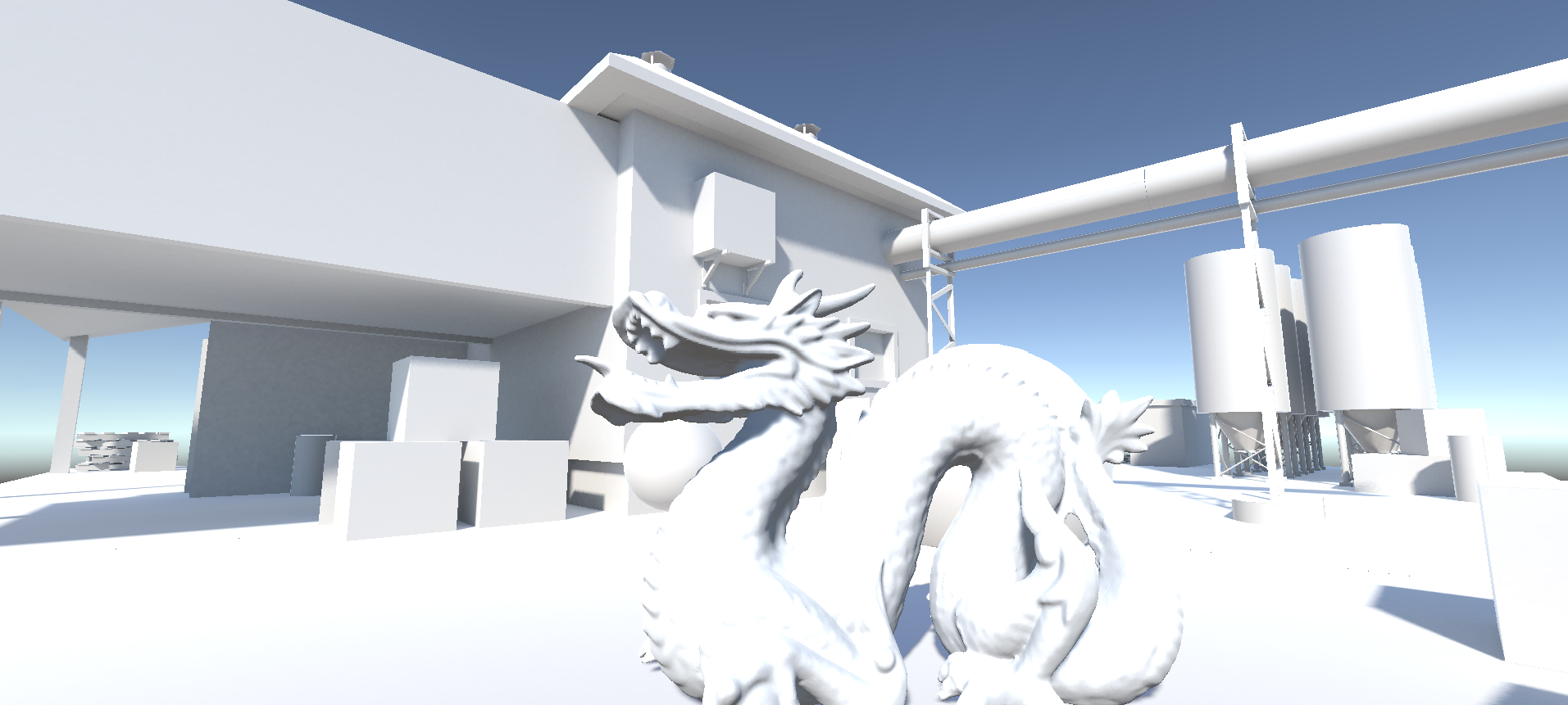
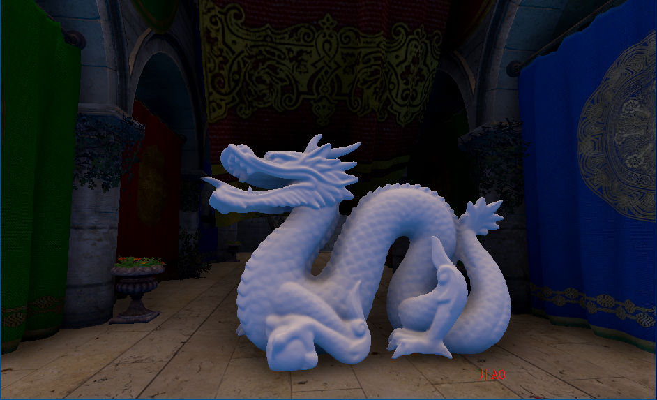
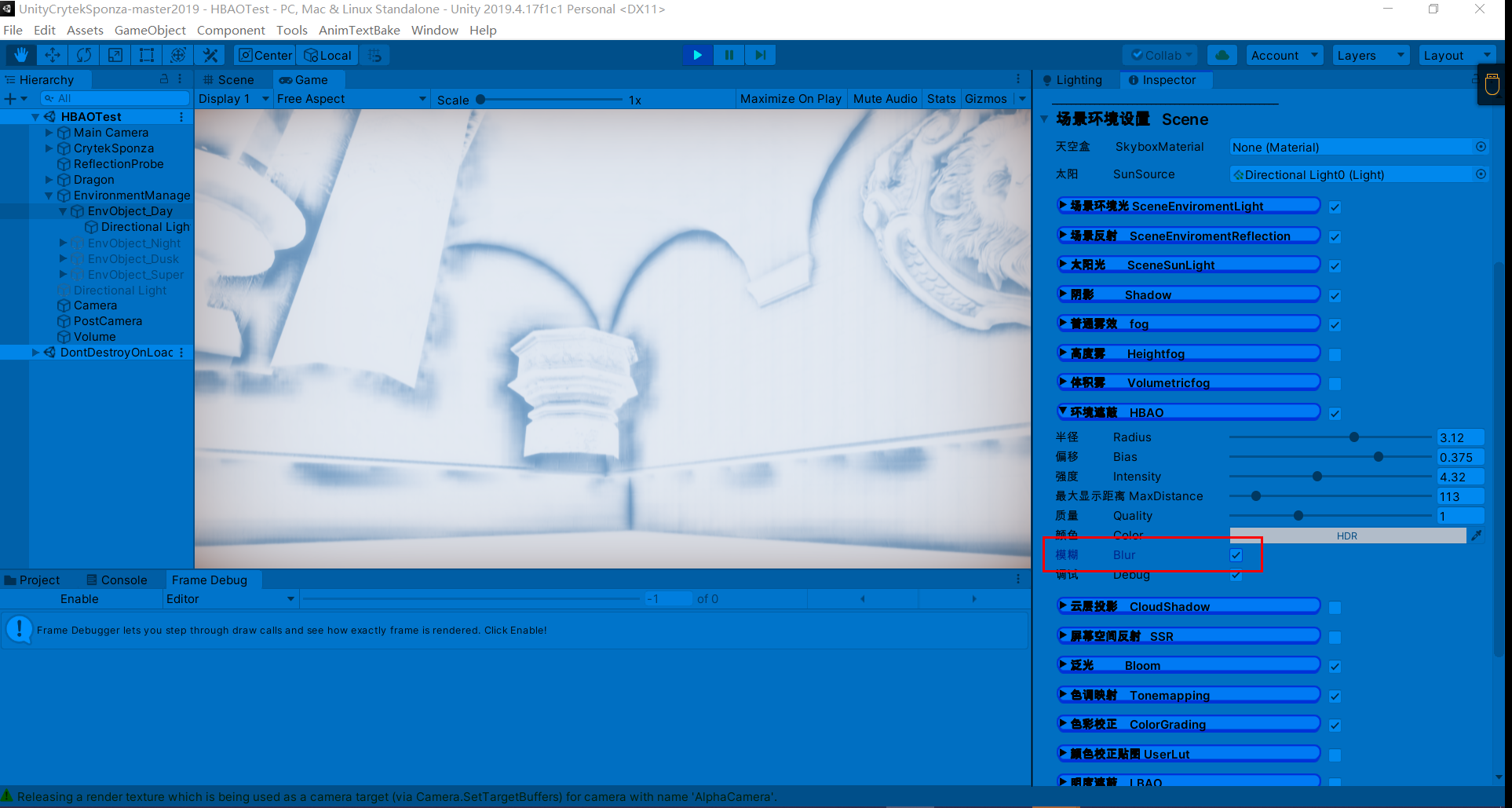
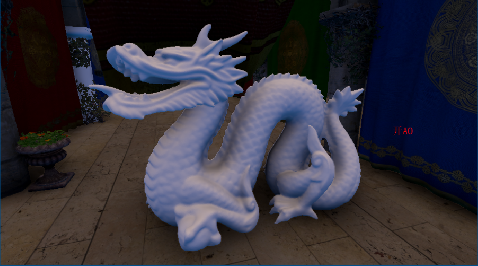
开启SSAO
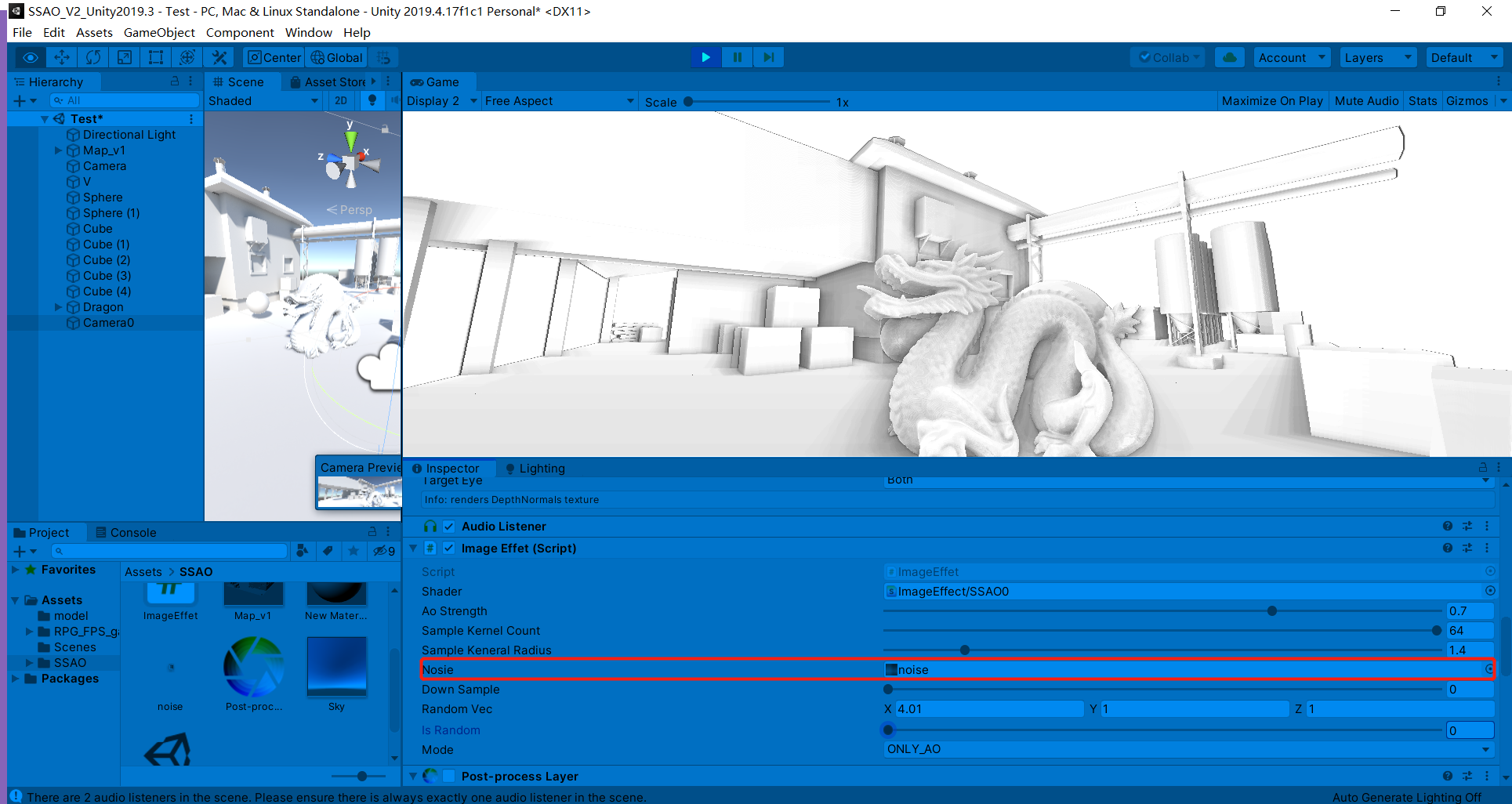
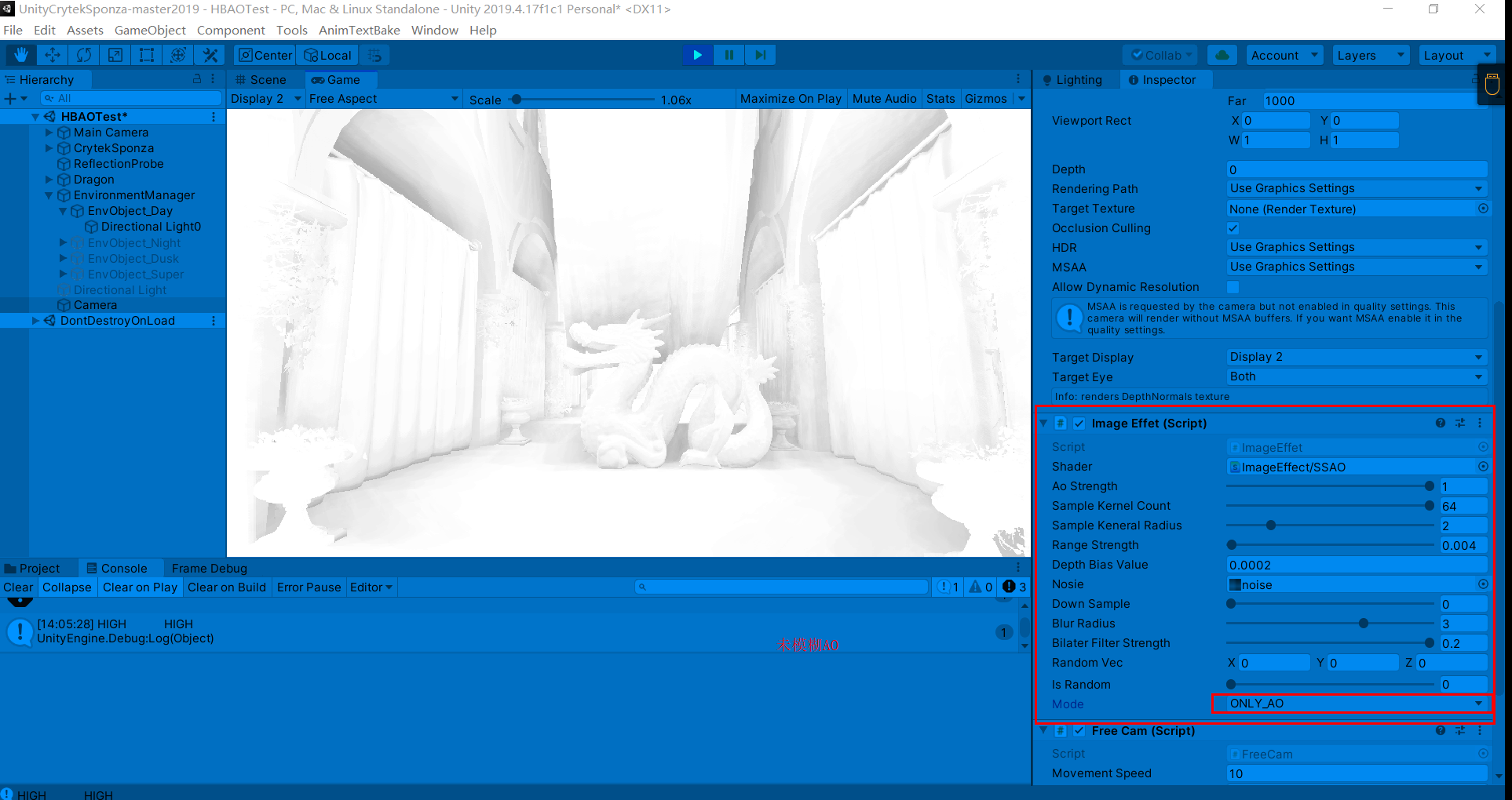
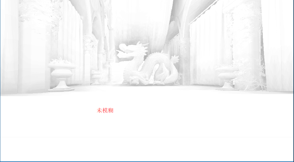
参数设置(未模糊AO),有两次开关AO操作
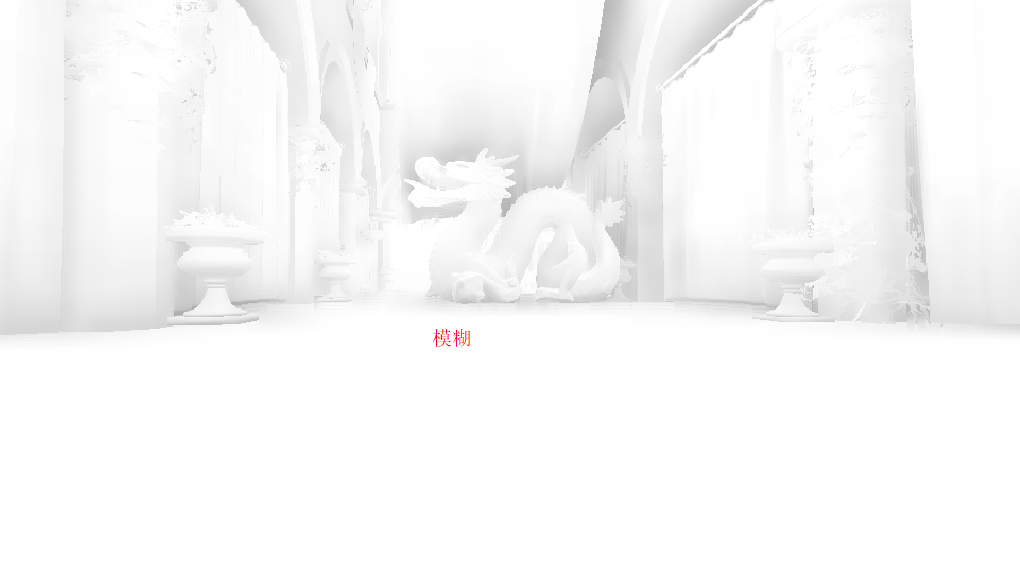
滤波后AO会平滑一些(这里个人看了一些文章后有一些观点,SSAO是工业上的一种近似,所以输出的物理结果并不会十分理想(不像离线渲染是实实在在地计算光线和物体),滤波这种消除噪声的操作也可以理解为缓解错误结果的办法)
Unity后处理组件中的后处理组件对SSAO进行了增强,有Scalable Ambient Obscurance和Multi Scale Volumetric Obscurance,两者相对SSAO的法线半球采样采用了更优方法,具体可阅读下方链接。
学习链接:Scalable Ambient Obscurance - 知乎 (zhihu.com)
shader复习与深入:Screen Space Ambient Occlusion(屏幕空间环境光遮蔽)-腾讯游戏学院 (qq.com)
官方文档:Ambient Occlusion | Package Manager UI website (unity3d.com)
说明:下方输出AO的方式采用Post-Process Debug组件
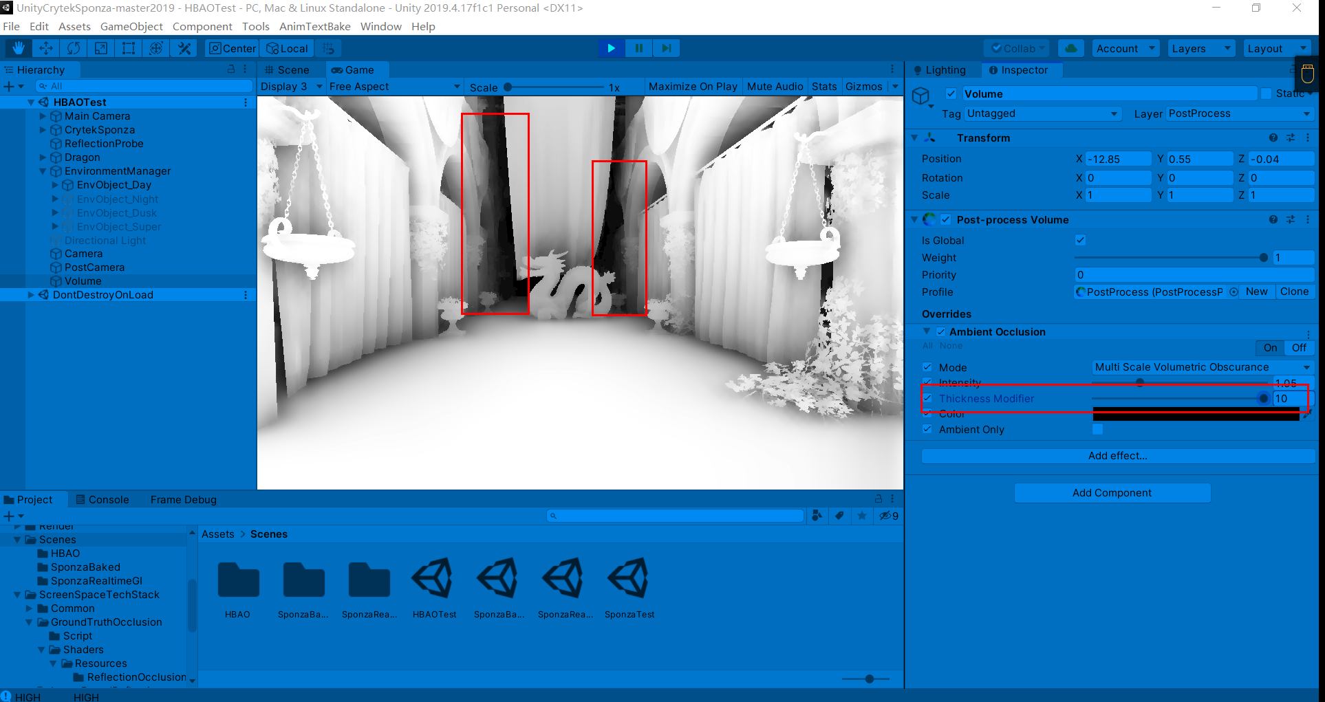
过强的AO强度会导致带状区域的出现(这在接下来讨论的几个AO方法中也会出现)
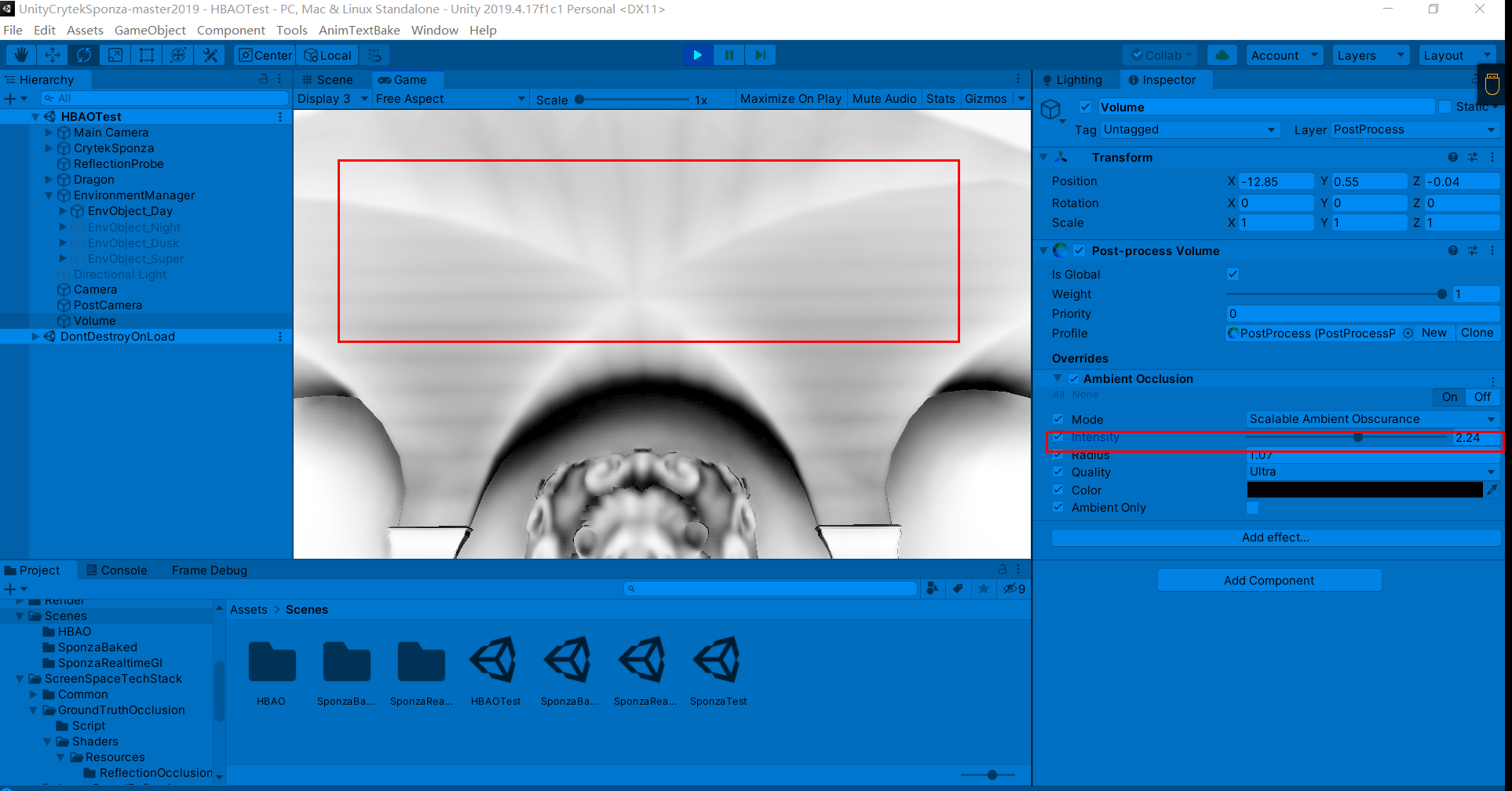
过大的AO半径则会导致严重错误的遮挡关系
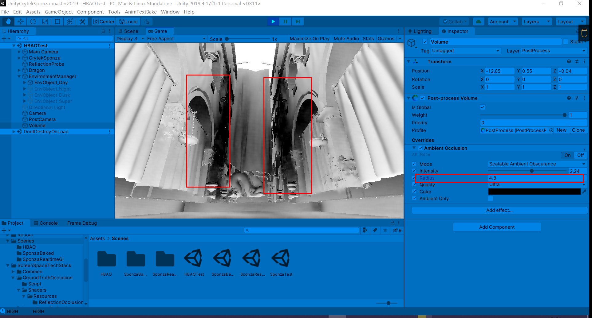
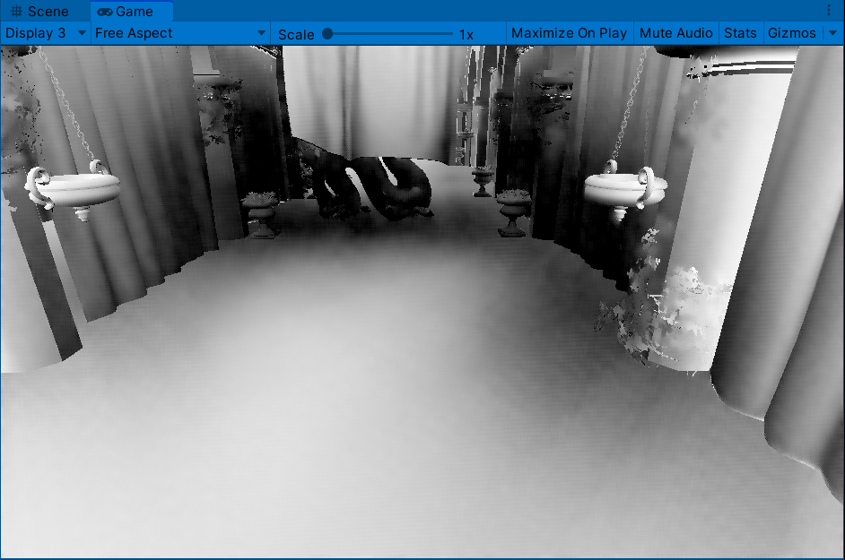
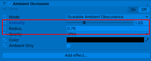
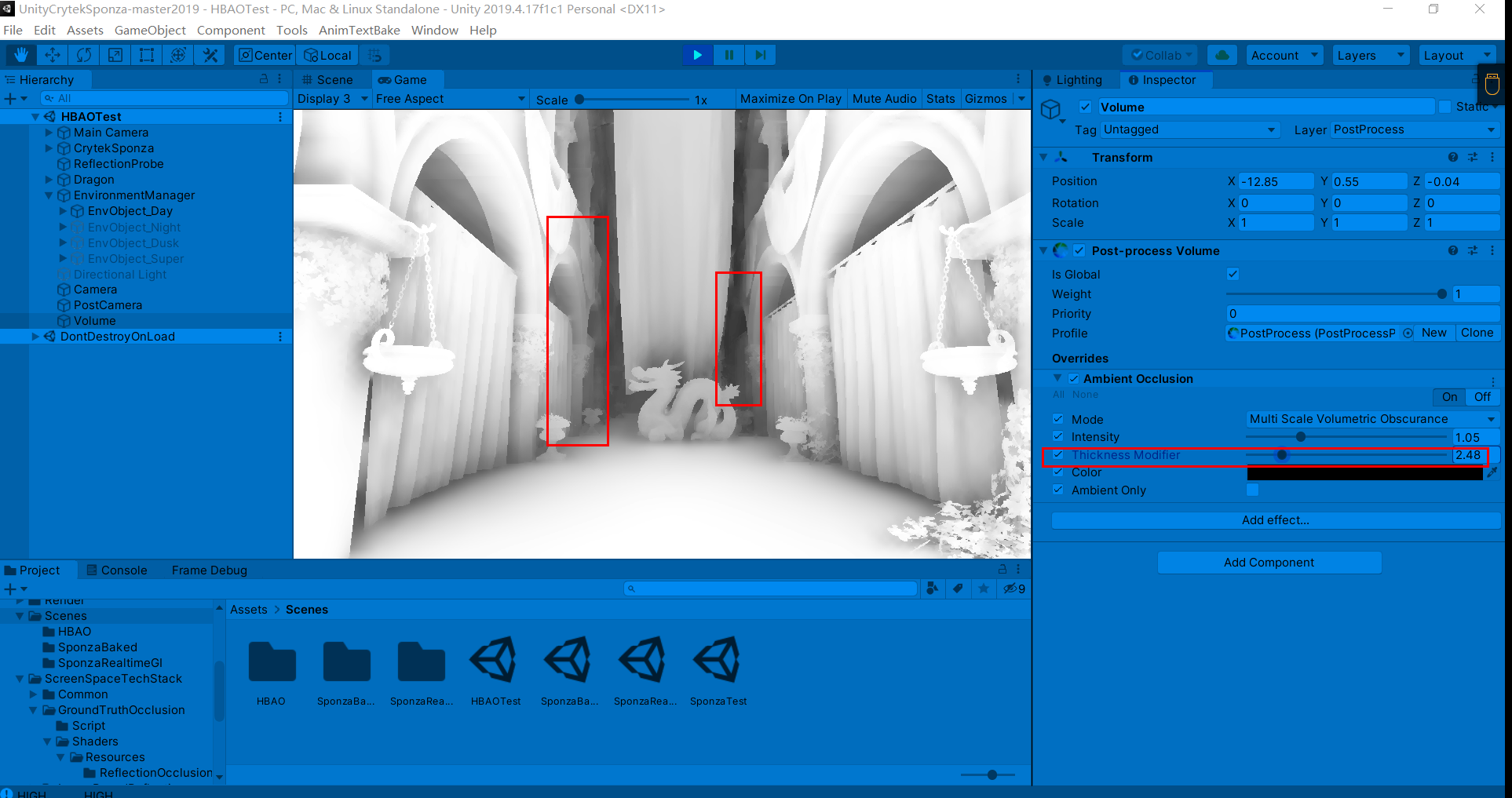
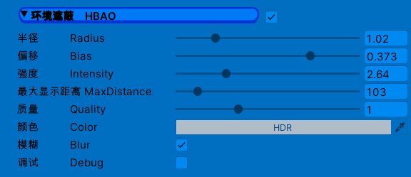
调节较为合适的参数如下:


Thickness Modifier:修改遮挡器的厚度。这会增加黑暗区域,但会在物体周围引入暗晕
直观上感觉MSVO比SAO计算量大,因为在运动中有抖动现象,同时感觉MSVO比SAO过渡更柔和

PPT:https://developer.download.nvidia.cn/presentations/2008/SIGGRAPH/HBAO_SIG08b.pdf
学习链接:HBAO(屏幕空间的环境光遮蔽) - 知乎 (zhihu.com)
HBAO(Image-space horizon-based ambient occlusion)是SSAO的改进,通过以下步骤进行AO:
1.对屏幕上一点像素P,分四方向进行光线步进(Ray Marching),每一个像素不能用相同的四个方向,所以要在方向上旋转一个随机角度
2.对其任意一方向得到一维高度场,在此方向步进(Marching)得到最大水平角(Horizon angle)
3.根据点P和法线N求切面角(tangent angle)
4.通过2,3得到的水平角和切面角,利用计算公式【AO(θ)=sin horizon(θ)-sin tangent(θ)】求出AO值
5.对剩下3方向做同样操作,得到点P四方形上(2D)AO值,相加后取平均得最终AO值
1.带状不连续问题(在SAO部分出现的那个问题),通过给切线角增加一个偏移量可以解决

2.ao值相差过大问题,在SSAO中也遇到过,直接输出AO值会导致周围几个AO值差过大,对比度太强,阴影过硬,可以用以下衰减公式解决
ao = saturate(1.0 - ao);//衰减,解决AO差值过大的不连续问题3.随机噪点,可以用模糊解决,同理SSAO
不模糊噪点时分明显
模糊后:
half4 frag_ao(v2f i, UNITY_VPOS_TYPE screenPos : VPOS) : SV_Target {
	//float3 P = FetchViewPos(i.uv2,depthNormal.zw);
	float3 P = FetchViewPos(i.uv2);//当前点

	clip(_MaxDistance - P.z);

	float stepSize = min((_AORadius / P.z), 128) / (STEPS + 1.0);//光线步进步长

	// (cos(alpha), sin(alpha), jitter)
	float3 rand = tex2D(_NoiseTex, screenPos.xy / 4.0).rgb;

	float2 InvScreenParams = _ScreenParams.zw - 1.0;

#if NORMALS_RECONSTRUCT
		float3 Pr, Pl, Pt, Pb;
		Pr = FetchViewPos(i.uv2 + float2(InvScreenParams.x, 0));
		Pl = FetchViewPos(i.uv2 + float2(-InvScreenParams.x, 0));
		Pt = FetchViewPos(i.uv2 + float2(0, InvScreenParams.y));
		Pb = FetchViewPos(i.uv2 + float2(0, -InvScreenParams.y));
		float3 N = normalize(cross(MinDiff(P, Pr, Pl), MinDiff(P, Pt, Pb)));
#else
	float4 normal = tex2D(_NormalBufferTex, i.uv2);
	float3 N = DecodeNormal(normal.xy);
	//float3 N = mul((float3x3)(UNITY_MATRIX_I_V),viewNormal);
	//float3 N = normal * 2 - 1;
#endif

	N = float3(N.x, -N.yz);

	float ao = 0;

	UNITY_UNROLL
	for (int d = 0; d < DIRECTIONS; ++d) {//对各方向
		float2 direction = RotateDirections(Directions[d], rand.xy);//随机旋转角度

		// Jitter starting sample within the first step
		float rayPixels = (rand.z * stepSize + 1.0);

		UNITY_UNROLL
		for (int s = 0; s < STEPS; ++s) {//进行光线步进

			float2 snappedUV = round(rayPixels * direction) * InvScreenParams  + i.uv2;

			//float4 depthNormal2 = tex2D(_CameraDepthNormalsTexture, snappedUV);

			//float3 S = FetchViewPos(snappedUV,depthNormal2.zw);
			float3 S = FetchViewPos(snappedUV);

			rayPixels += stepSize;

			float contrib = ComputeAO(P, N, S);
			ao += contrib;

		}
	}

	ao *= (_AOmultiplier / (STEPS * DIRECTIONS));

	ao = saturate(1.0 - ao);//衰减公式,解决AO差值过大的不连续问题

	return half4(ao, 0,0,1);
}
//分四个方向步进
#define DIRECTIONS 4
//光线步进次数
#define STEPS 3
static const float2 Directions[8] = {
float2(1,0),
float2(-0.5000001,0.8660254),
float2(-0.4999999,-0.8660254),
float2(0,1),
};
half3 DecodeNormal (half2 enc)
{
half2 fenc = enc*4-2;
half f = dot(fenc,fenc);
half g = sqrt(1-f/4);
half3 n;
n.xy = fenc*g;
n.z = 1-f/2;
return n;
}
//inline float3 FetchViewPos(float2 uv,float2 depth) {
// float z = DecodeFloatRG (depth) * _ProjectionParams.z;
// return float3((uv * _UVToView.xy + _UVToView.zw) * z, z);
//}
inline float3 FetchViewPos(float2 uv) {
float z = DECODE_EYEDEPTH(SAMPLE_DEPTH_TEXTURE(_CameraDepthTexture, uv));
return float3((uv * _UVToView.xy + _UVToView.zw) * z, z);
}
inline float Falloff(float distanceSquare) {
// 1 scalar mad instruction
return distanceSquare * _NegInvRadius2 + 1.0;
}
inline float ComputeAO(float3 P, float3 N, float3 S) {
float3 V = S - P;
float VdotV = dot(V, V);
VdotV = clamp(VdotV,0.01,10000); // fixed precision
float NdotV = dot(N, V) * rsqrt(VdotV);
//return saturate(Falloff(VdotV));
// Use saturate(x) instead of max(x,0.f) because that is faster on Kepler
return saturate(NdotV - _AngleBias) * saturate(Falloff(VdotV));
}
inline float3 MinDiff(float3 P, float3 Pr, float3 Pl) {
float3 V1 = Pr - P;
float3 V2 = P - Pl;
return (dot(V1, V1) < dot(V2, V2)) ? V1 : V2;
}
inline float2 RotateDirections(float2 dir, float2 rot) {
return float2(dir.x * rot.x - dir.y * rot.y,
dir.x * rot.y + dir.y * rot.x);
}
PPT:https://iryoku.com/downloads/Practical-Realtime-Strategies-for-Accurate-Indirect-Occlusion.pdf
学习链接:UE4 Mobile GTAO 实现(HBAO续) - 知乎 (zhihu.com)
Unity_GroundTruth-Oclusion - 知乎 (zhihu.com)
实时渲染器开发(四) GTAO原理与实践 - 知乎 (zhihu.com)
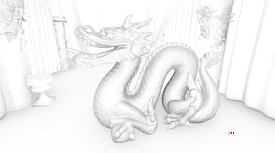
GTAO(GroundTruth-Oclusion)在HBAO基础上增加余弦项Cosine Weight操作使AO计算的物理性更精准,同时还增加了AO的MutiBounce弹射效果。另外,在AO基础上增加了RO(ReflectionOcclusion)。可以利用双边滤波,Temporal滤波来优化最终AO。
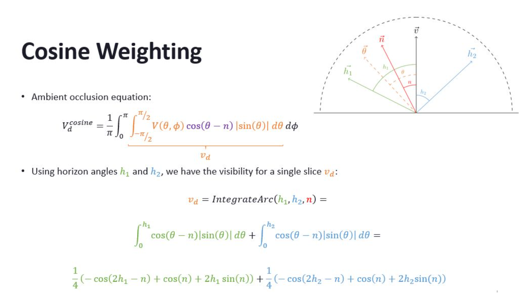
half IntegrateArc_CosWeight(half2 h, half n)//计算余弦项
{
    half2 Arc = -cos(2 * h - n) + cos(n) + 2 * h * sin(n);
    return 0.25 * (Arc.x + Arc.y);
}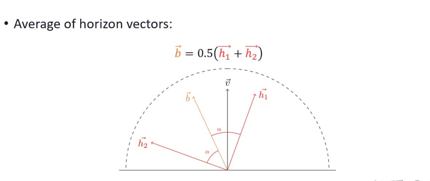
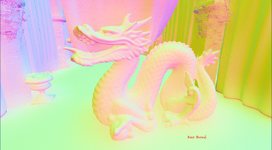
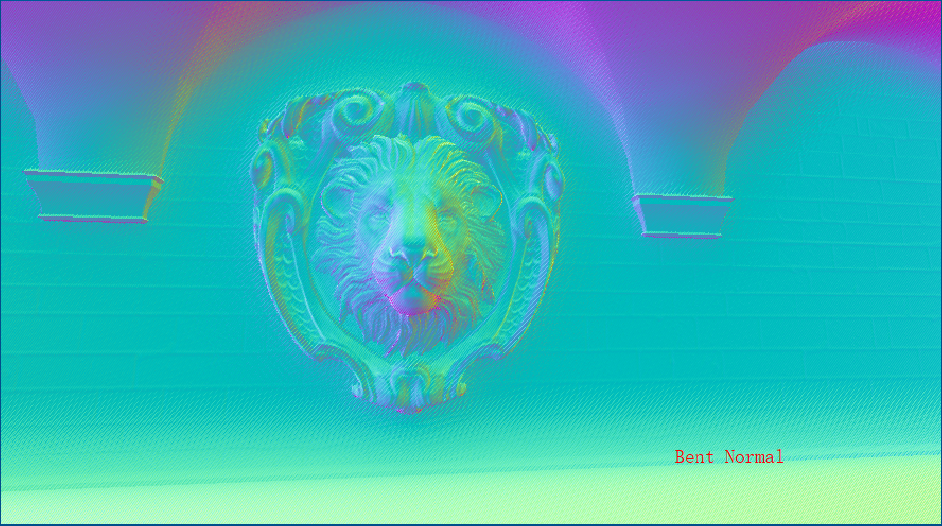
//利用h1和h2和viewDir构建一个坐标系去推算出BentAngle以重建BentNormal
bentAngle = (h.x + h.y) * 0.5;//average both horizon angles
BentNormal += viewDir * cos(bentAngle) - tangent * sin(bentAngle);近似全局光照
inline half3 MultiBounce(half AO, half3 Albedo)
{
	half3 A = 2 * Albedo - 0.33;
	half3 B = -4.8 * Albedo + 0.64;
	half3 C = 2.75 * Albedo + 0.69;
	return max(AO, ((AO * A + B) * AO + C) * AO);
}
inline float ApproximateConeConeIntersection(float ArcLength0, float ArcLength1, float AngleBetweenCones)
{
float AngleDifference = abs(ArcLength0 - ArcLength1);
float Intersection = smoothstep(0, 1, 1 - saturate((AngleBetweenCones - AngleDifference) / (ArcLength0 + ArcLength1 - AngleDifference)));
return Intersection;
}
//计算RO
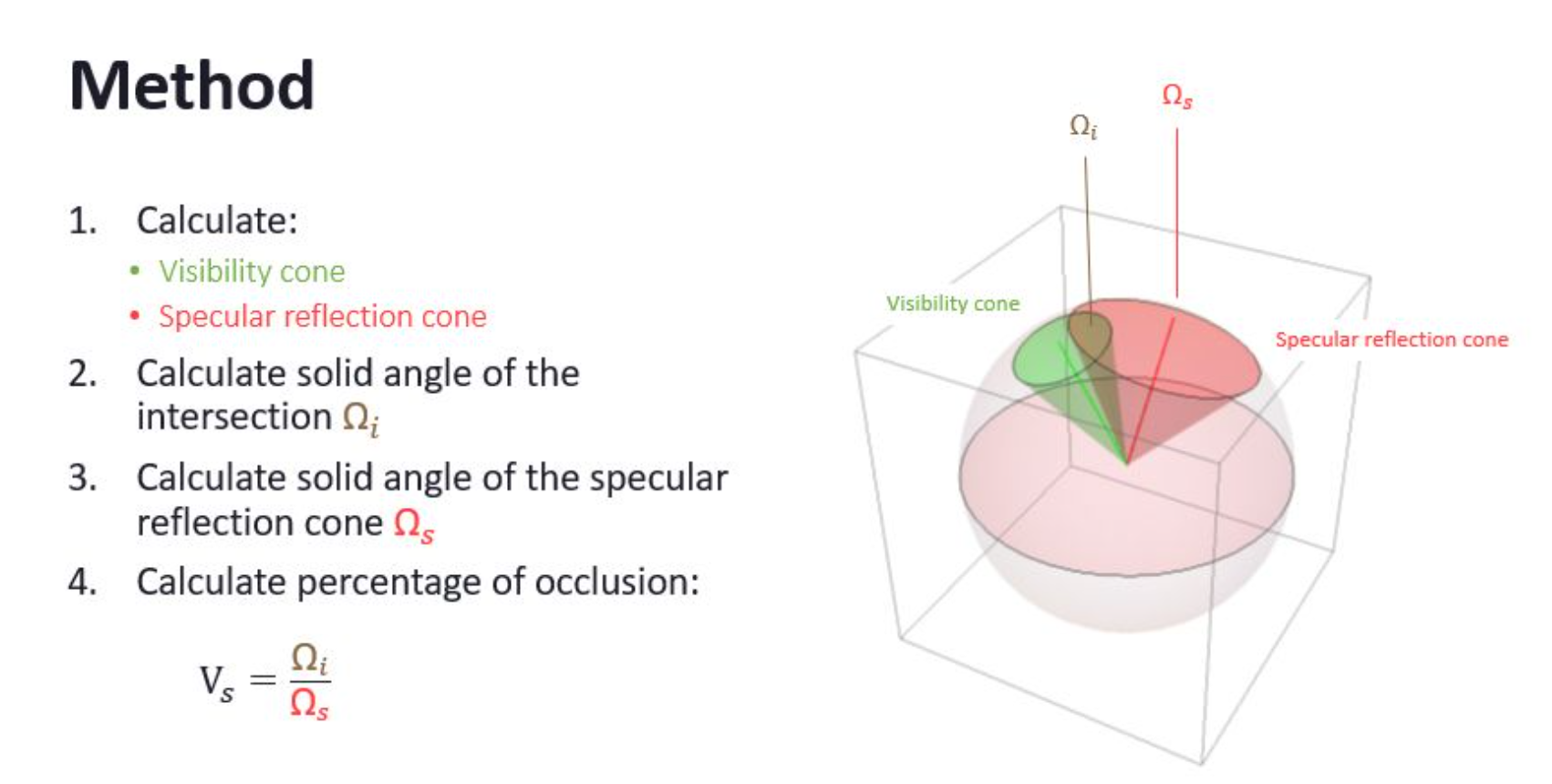
inline half ReflectionOcclusion(half3 BentNormal, half3 ReflectionVector, half Roughness, half OcclusionStrength)
{
half BentNormalLength = length(BentNormal);
half ReflectionConeAngle = max(Roughness, 0.1) * PI;
half UnoccludedAngle = BentNormalLength * PI * OcclusionStrength;
half AngleBetween = acos(dot(BentNormal, ReflectionVector) / max(BentNormalLength, 0.001));
half ReflectionOcclusion = ApproximateConeConeIntersection(ReflectionConeAngle, UnoccludedAngle, AngleBetween);//BentNormal作为VisibilityCone去和SpecularCone求交得到ReflectionOcclusion
ReflectionOcclusion = lerp(0, ReflectionOcclusion, saturate((UnoccludedAngle - 0.1) / 0.2));
return ReflectionOcclusion;
}将整个半球面用极坐标系表示,沿着观察方向,将半球面按照角度变化进行切片:
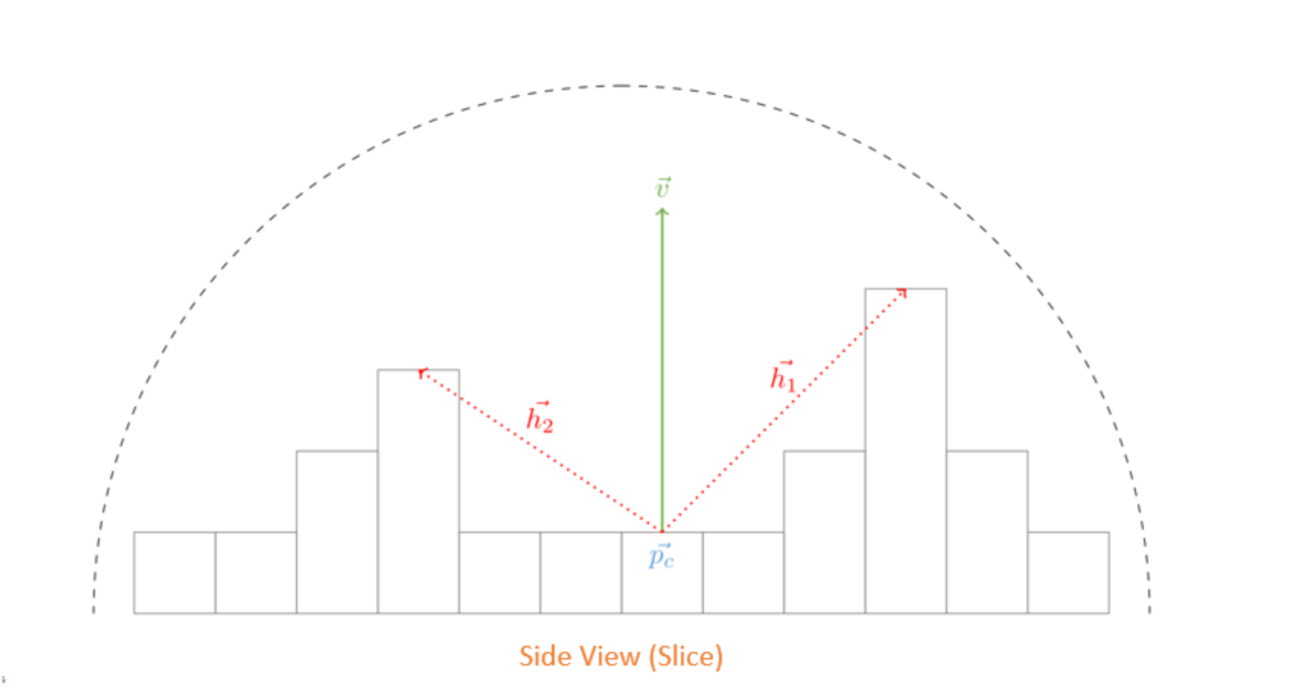
在每个切面上,寻找两端未被遮挡住的角度,称为水平角(horizonal angle),计算每个切片上的AO值,再将所有切片上的结果进行积分。
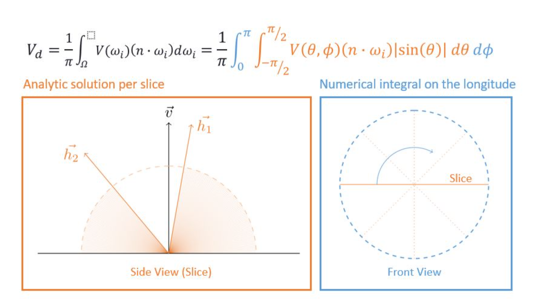
在切片上寻找水平角的过程,通常是沿着某个方向采样深度值,得到最大水平角。
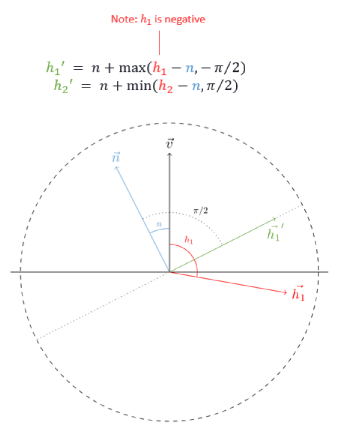
限制(clamp)水平角范围。
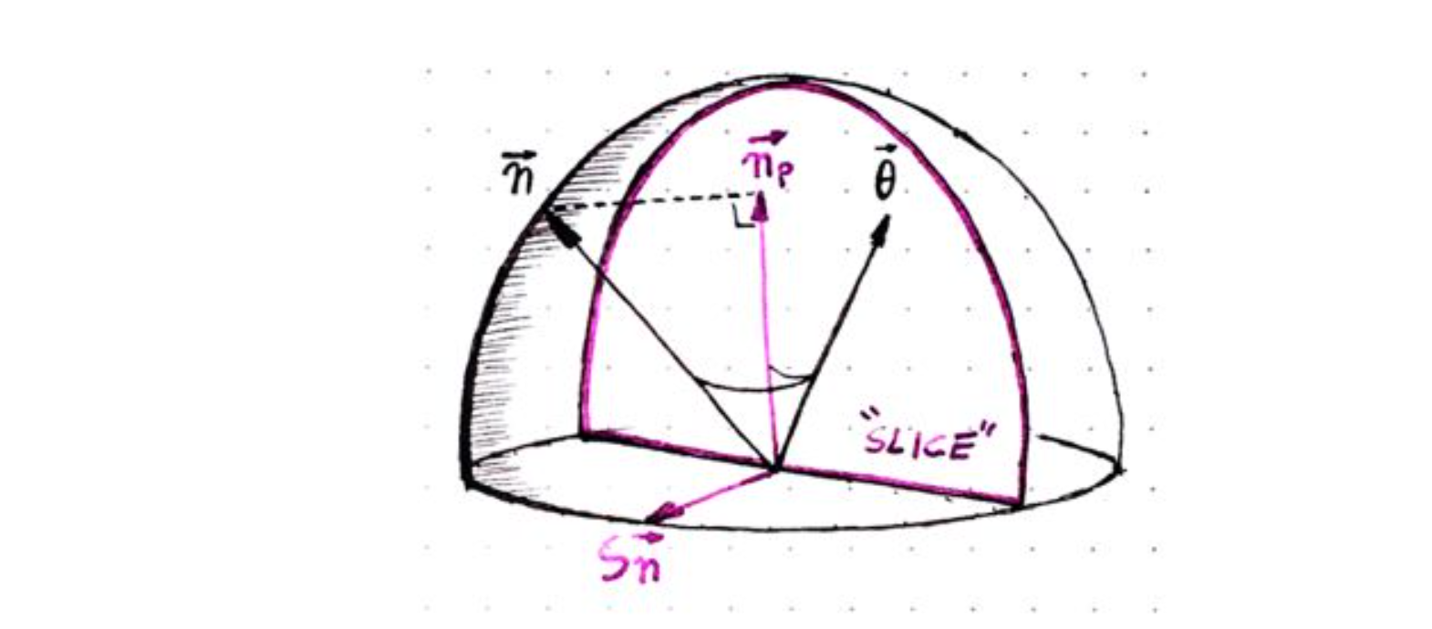
得到每个切面上的两个最大水平角后,就可以在切面上进行积分,计算当前切面上的AO值。(Cosine Weighting)。
将物体表面的法线投影到切面(选取切面时,可以加上一些噪声,这样每个点选取的切面都有变化,来实现降噪的目的)。
for (int i = 0; i < NumCircle; i++)
{
    angle = (i + noiseDirection + _AO_TemporalDirections) * (UNITY_PI / (half)NumCircle);
    sliceDir = half3(half2(cos(angle), sin(angle)), 0);
    slideDir_TexelSize = sliceDir.xy * _AO_RT_TexelSize.xy;
    h = -1;

    for (int j = 0; j < NumSlice; j++)
    {
        uvOffset = slideDir_TexelSize * max(stepRadius * (j + initialRayStep), 1 + j);
        uvSlice = uv.xyxy + float4(uvOffset.xy, -uvOffset);

        ds = GetPosition(uvSlice.xy) - vPos;
        dt = GetPosition(uvSlice.zw) - vPos;

        dsdt = half2(dot(ds, ds), dot(dt, dt));
        dsdtLength = rsqrt(dsdt);

        falloff = saturate(dsdt.xy * (2 / pow2(radius)));

        H = half2(dot(ds, viewDir), dot(dt, viewDir)) * dsdtLength;
        h.xy = (H.xy > h.xy) ? lerp(H, h, falloff) : lerp(H.xy, h.xy, thickness);
    }

    planeNormal = normalize(cross(sliceDir, viewDir));
    tangent = cross(viewDir, planeNormal);
    projectedNormal = viewNormal - planeNormal * dot(viewNormal, planeNormal);
    projLength = length(projectedNormal);

    cos_n = clamp(dot(normalize(projectedNormal), viewDir), -1, 1);
    n = -sign(dot(projectedNormal, tangent)) * acos(cos_n);

    h = acos(clamp(h, -1, 1));
    h.x = n + max(-h.x - n, -UNITY_HALF_PI);
    h.y = n + min(h.y - n, UNITY_HALF_PI);

    //利用h1和h2和viewDir构建一个坐标系去推算出BentAngle以重建BentNormal
    bentAngle = (h.x + h.y) * 0.5;//average both horizon angles

    BentNormal += viewDir * cos(bentAngle) - tangent * sin(bentAngle);
    Occlusion += projLength * IntegrateArc_CosWeight(h, n);
}(AO切换RO切换BentNormal,最后对比合成图片)


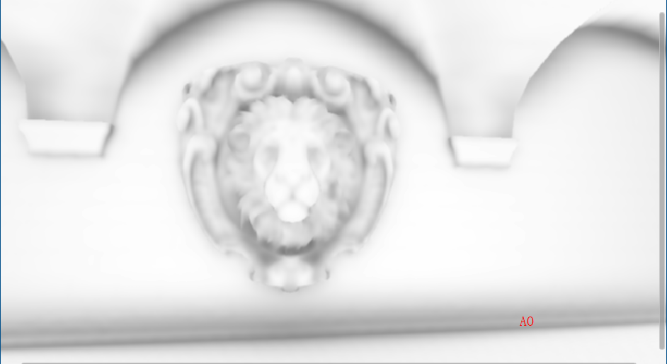
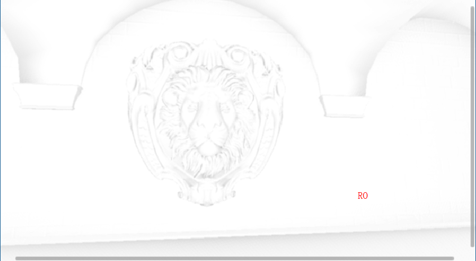
实时的AO物理的正确性较差,但对采样方式以及对周围采样区域的计算方式的优化可以提升直观的视觉体验或者生成AO的速度,相对于静态烘焙的AO,实时AO有了更好的交互,但是随着人物和周围建筑距离的变化,AO的误差也可能增加,造成AO区域的抖动或整个场景过暗情况。
屏幕空间的算法依赖于深度信息,这里汇总一些对学习求取深度信息的链接
tex2Dproj和tex2D的区别 - 知乎 (zhihu.com)