Advanced Lane Finding

Report - Advanced Lane Finding - Udacity Self Driving Car
Advanced Lane Finding Project
The goals / steps of this project are the following:
- Compute the camera calibration matrix and distortion coefficients given a set of chessboard images.
- Apply a distortion correction to raw images.
- Use color transforms, gradients, etc., to create a thresholded binary image.
- Apply a perspective transform to rectify binary image ("birds-eye view").
- Detect lane pixels and fit to find the lane boundary.
- Determine the curvature of the lane and vehicle position with respect to center.
- Warp the detected lane boundaries back onto the original image.
- Output visual display of the lane boundaries and numerical estimation of lane curvature and vehicle position.
TL-DR:
Here's the video of the car.
Rubric Points
Here I will consider the rubric points individually and describe how I addressed each point in my implementation.
###Writeup / README
###Camera Calibration
####1. Briefly state how you computed the camera matrix and distortion coefficients. Provide an example of a distortion corrected calibration image.
The code for this step is contained in the file in "./camera_calibrator.py"
I start by preparing "object points", which will be the (x, y, z) coordinates of the chessboard corners in the world. Here I am assuming the chessboard is fixed on the (x, y) plane at z=0, such that the object points are the same for each calibration image. Thus, objp is just a replicated array of coordinates, and objpoints will be appended with a copy of it every time I successfully detect all chessboard corners in a test image. imgpoints will be appended with the (x, y) pixel position of each of the corners in the image plane with each successful chessboard detection.
I then used the output objpoints and imgpoints to compute the camera calibration and distortion coefficients using the cv2.calibrateCamera() function. I applied this distortion correction to the test image using the cv2.undistort() function and obtained this result:

###Pipeline (single images)
####1. Provide an example of a distortion-corrected image. Using the camera calibration parameters from above, the image of a road is undistorted as shown below:

####2. Describe how (and identify where in your code) you used color transforms, gradients or other methods to create a thresholded binary image. Provide an example of a binary image result.
I used a combination of color and gradient thresholds to generate a binary image (thresholding steps at lines 171 through 194 in file threshold_detector.py).
I used Sobel edge detection (kernel size 7), to get the direction and magnitude of gradients, and extracted White and Yellow colors via masking using cv2.inRange(). The values for thresholds were determined by trial and error.
Here's an example of my output for this step.

As it shows, the lane edges are prominent in some cases, and there's some noise from other artefacts (e.g. shaded trees, etc.)
####3. Describe how (and identify where in your code) you performed a perspective transform and provide an example of a transformed image.
The code for my perspective transform is in the file perspective.py, which includes a class PerspectiveTransformer
The forward_transform() function takes as inputs an image (img), and produces a bird's eye view of the image.
The inverse_transform() function performs the inverse transformation, i.e. from a bird's eye view back to the camera-front view.
Through trial and error, I found and hardcoded the source and destination points in the following manner:
SRC_POINTS = np.float32([
    (130, 700),   # Bottom left
    (540, 465),   # Top Left
    (740, 465),   # Top Right
    (1200, 700)   # Bottom Right
])

DEST_POINTS = np.float32([
    (SRC_POINTS[0][0] + OFFSET, 720),
    (SRC_POINTS[0][0] + OFFSET, 0),
    (SRC_POINTS[-1][0] - OFFSET, 0),
    (SRC_POINTS[-1][0] - OFFSET, 720)
])
This resulted in the following source and destination points:
| Source | Destination |
|---|---|
| 130, 700 | 380, 720 |
| 540, 465 | 380, 0 |
| 740, 465 | 950, 0 |
| 1200, 700 | 950, 720 |
I verified that my perspective transform was working as expected by drawing the src and dst points onto three test images and its warped counterpart to verify that the lines appear parallel in the warped image.

####4. Describe how (and identify where in your code) you identified lane-line pixels and fit their positions with a polynomial?
In the file lane_detector.py is the class LaneDetector which has functions window_fit() and sliding_window_fit().
These functions take an image and attempt to find lane lines using polynomial fit.
The function sliding_window_fit uses the sliding window algorithm to divide an image in 9 sliding windows and finds peaks using histogram technique.
The function window_fit finds lane lines in the vicinity of previously found lanes. Both functions return left_fit and right_fit polynimal coefficients for the left and right lanes.
The code used is similar to the one in Udacity lessons.
####5. Describe how (and identify where in your code) you calculated the radius of curvature of the lane and the position of the vehicle with respect to center.
Lane curvature is found in method find_lane_curvature() of the class LaneDetector. This method takes an image and returns the averge lane curvature (mean of left and right curve radii).
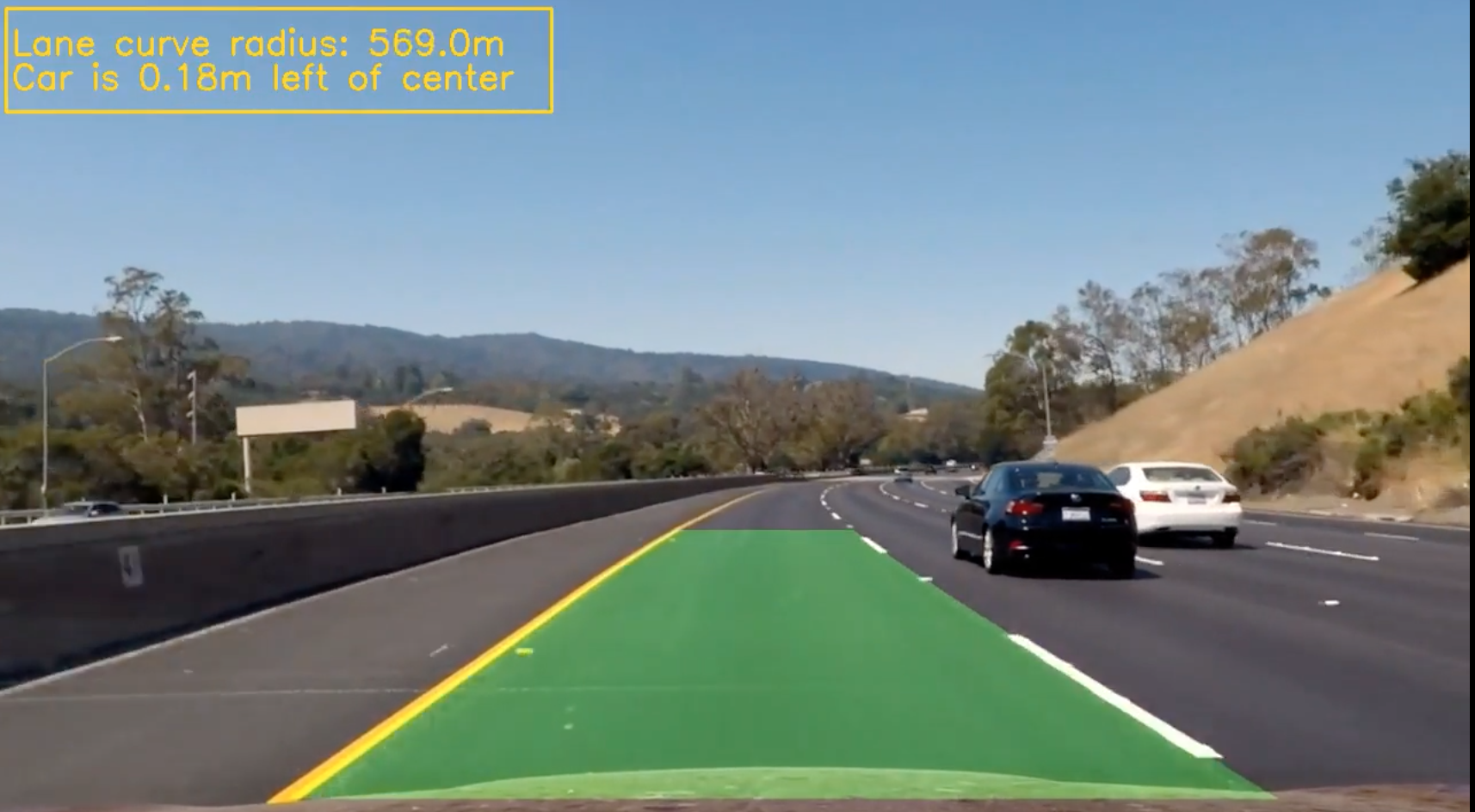
####6. Provide an example image of your result plotted back down onto the road such that the lane area is identified clearly.
Finally, once the lane curve radii are found, we draw a polygon overlay on the image. This is done in draw_polygon() in the class LaneDetector.
Additionally, we display a short dashboard with lane information, using function display_dashboard also in LaneDetector.
Here is an example of my result on a test image:

###Pipeline (video)
####1. Provide a link to your final video output. Your pipeline should perform reasonably well on the entire project video (wobbly lines are ok but no catastrophic failures that would cause the car to drive off the road!).
Here's a link to my video result
###Discussion
####1. Briefly discuss any problems / issues you faced in your implementation of this project. Where will your pipeline likely fail? What could you do to make it more robust?
This project was challenging in several ways. The easier parts of the project were calibrating the camera, thresholding the image and warping the perspective.
Finding lane lines turned out to be somewhat challenging. The thresholding parameters and warping parameters took some trial and error (and a lot of frustration, too).
Getting the pipeline to work end-to-end was hence time consuming trial and error, as sometimes the lane lines were not detected properly due to inability to detect lane edges.
Images that were either too dark or too bright, or with lanes with extreme curvature posed a challenge. However, with some tuning, I was able to make it work.
The current setup works for the regular project video; however, it does not work on the challenge videos yet, as the lanes are either curved, and there are extra markings on the road, or the lanes are too bright/shaded.