There are two binaries in this Cargo project:
line_follower_gui: the simulation with a graphical interfaceline_follower_cli: a CMA-ES-based optimization algorithm to find the best controller parameters (Kp, Ki, Kd and speed) for the robotpath_editor: a simple graphical tool to create a path for the robot to follow
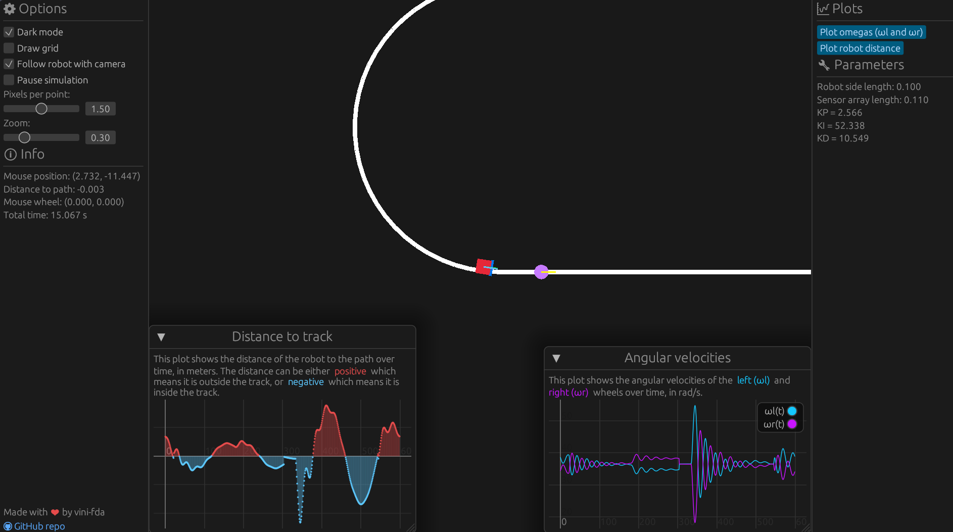
This is a simple simulation of a line follower robot. The robot is controlled by a feedback controller that uses the light sensors to detect the line. The robot is placed on a track, which is a smooth curve. It is controlled by a two-wheel differential drive (TWD), which means that it can move in a straight line if the wheels are moving at the same speed and make a turn if the wheels are moving at different speeds.
Here's an image of the simulation:
You can download the binaries from the releases page. There are binaries for Windows, Linux and macOS on x86_64 architectures.
You can also build the binaries from source. You'll need to have Rust installed. You can install it with rustup.
Once you have Rust installed, you can clone this repository and build the binaries with Cargo:
git clone git@github.com:vini-fda/line-follower-rs.git
cd line-follower-rs
cargo build --release --allJust run the executable by double-clicking it or running it from the command line. Then, you can either use the default track or load a track from a JSON file.
The line_follower_cli binary is used to find the best controller parameters for the robot. It uses the CMA-ES algorithm to optimize the parameters. The algorithm is implemented in the cmaes crate.
When running the tool, you should see output similar to this one:
Running optimization...
aCMA-ES with dimension=4, lambda=300, seed=16288843452448529938
 Gen #  | f evals | Best function value | Axis Ratio |   Sigma    |  Min std   |  Max std
-------------------------------------------------------------------------------------------
      1 |     300 | -4.554237783676e+04 | 1.4008e+00 | 9.9837e-02 | 8.8225e-02 | 1.1155e-01
      2 |     600 | -4.605828879559e+04 | 1.8923e+00 | 1.0006e-01 | 6.8764e-02 | 1.2275e-01
      3 |     900 | -4.050201670353e+04 | 2.5375e+00 | 1.1017e-01 | 6.3484e-02 | 1.4004e-01
      4 |    1200 | -3.839506730294e+04 | 2.9960e+00 | 1.1307e-01 | 5.8940e-02 | 1.4105e-01
...
Terminated with reason(s): `NoEffectCoord`
Current best function value: 1.0548456113650464e2
Overall best function value: 1.0548497399813101e2
Final mean:
  ┌                    ┐
  │ 2.9682382637441114 │
  │   63.3239093521287 │
  │ 14.144606408009336 │
  │  1.378692186196955 │
  └                    ┘
Wrote outputs to file "optimal_params_2023-06-09_23-20-18.txt"
The path_editor binary is a simple graphical tool to create a path for the robot to follow. It can be used to create a track for the line_follower_gui binary in the JSON format.
- Add the graphical representation of the robot
- Initially, just a simple rectangle with indicators for the sensors (front)
- Implement a simple library for the geometry of the track
- Map simulation units to graphics/screen-space units
- Simulation units should be, by default, equal to the real-world units in SI (i.e. 1 simulation unit = 1 meter)
- When showing the simulation, a grid could have axes with configurable real-world units (i.e. 1 meter = 1 grid unit)
- Add a camera to the simulation
- Add zoom and pan
- Add a grid with world coordinates (can be toggled)
- Implement a simple library for the simulation of the robot
- Needs a stable integration scheme
- Needs a way to specify the robot's dynamics, i.e. the equations of motion in terms of the parameters of the robot (mass, inertia, etc.)
- State-space representation is ideal
- The time step should be configurable (and could be smaller than the graphics time step, so that the simulation is more accurate)
- Needs a stable integration scheme
- Simulation must be decoupled from the graphics
- We may want to run the simulation at a higher frequency than the graphics, possibly without displaying the graphics at all
- There should be a discrete amount of light sensors (say, 7) to indicate how far off the line it is
- There should be an encoder to measure the angular velocity of the robot's wheels
- The scalar velocity of the robot can be calculated from the angular velocity of the wheels and the radius of the wheels under the no-slip condition
- There are two wheels on the robot, which can be controlled independently
- This can create a differential drive robot, which moves in a straight line if the wheels are moving at the same speed and makes a turn if the wheels are moving at different speeds
- The robot will implement some sort of controller
- The controller will follow a feedback control scheme using sensor data
- The controller must be discretized using a state-space representation
- As extra work, we could treat the controller sample frequency as different from the simulation frequency
- The track is just a collection of points
- The track should be closed, i.e. the last point should be connected to the first point
- The track should be a smooth curve
- Create auxiliary library to implement arcs and straight lines
- Add elements to control the simulation
- Add a button to start/stop the simulation
- Add a button to reset the simulation
- Add a slider to control the speed of the simulation
- Plot the robot's orientation (angle) and error (detected by the sensors) in real-time graphs
- Add a button to toggle the graphs


