![]()
The aim of this work was to investigate the potential of an automated solution for inspection of ground-embedded runway-lights, with no humans-in-the-loop. A prototype differential-drive mobile robot featuring two monoscopic cameras, communicating with a database of positions from ground-embedded runway-lights was built and tested on an airport. Tests indicated promising results for further research and expansion of the current robotic-platform-solution as a functional and viable solution for automatic inspection of runway-lights. Accuracy test requirements demanded a maximum distance error of 15 meters with a maximum angular error of 2.9°. Results showed the robot was able to maneuver around a predefined path with a mean heading angular error of 1.6°. Runway light-detection test of a set of 58 runway-lights concluded on a 6 meter accuracy, with a maximum angular error of 1.7°. Both of these results within the required specifications. The significance of these results demonstrate the viability of this paper's robotic system in runway light-detection within minimum specification, as well as usage of the detection methods to determine which lights need human intervention for replacement or maintenance.
Thousands of planes land every day in airports around the world . In order to navigate the runways, indicator lights for landing zones and taxi routes are necessary. Failure in lighting can result in catastrophic failure in plane navigation. Runway light inspection is therefore necessary and required by regulation, with this procedure currently being done manually in airports around the world. Manual inspection of runway lights is done by driving to all light locations and verifying colour, intensity, functionality, and visibility. Issues of this method are the monotonous nature of the task, leading to possible human errors, along with the associated dangers of unnecessary travel on the runways of an active airport. Automated inspection of airport runways currently only pertains to pavement crack detection and detection of debris on the runway obot}. This work was unable to find a fully automated solution of both the inspection robot without humans-in-loop or any literature on automated runway light detection. This paper therefore presents a novel full stack solution for inspection of airport runway lights via two monoscopic cameras mounted on the front and rear of a prototype Autonomous Mobile Robot platform (AMR). The focus of this paper will be an autonomous platform for the detection and database association of ground embedded circular lights, with a diameter of 30 cm, placed on the taxiway and runway of Aarhus Airport. The location of these lights will be associated to the position of an existing database, with the intent of affirming whether the light is visible at the location and afterwards calculating a confidence score. Summarized in section 2 is the overall system architecture along with the specifications and theories of the subsystem components. Section 4 presents the test descriptions along with results of the tested parts of the implementation. The paper is concluded in section 4.
The system architecture of the autonomous runway inspection robot has been designed for reliability, modularity, and performance. The robot platform is equipped with an inertial measurement unit with a magnetometer (IMU). Individual wheel speeds are determined by reading out an encoder on each wheel. High precision Global Navigation Satellite System (GNSS) is used in conjunction with real time kinematics as a position sensor. Lights are detected by both frontal and rear cameras in order to inspect both sides in a single pass and reduce the inspection time. The camera images are processed, the center of the light hypotheses are extracted and the relative position to the camera frame is estimated. The hypotheses are then associated to the known database and the light status is updated.

The chosen computing system consists of a high performance embedded application computer and a low power autonomous control unit. The application control unit is dedicated to vision-based perception and all relevant application processes. The autonomous control unit runs all other software packages that keep the robot functional even without the application control unit. All processing units communicate via Ethernet. The designed software system runs on the ROS Noetic framework. NTP is used to synchronize the clocks of all processing units the local network. The autonomous control unit also runs the low level controllers and low level state machine of the robot platform. The state estimation predicts an accurate high frequency pose for the trajectory controller and the light association. In order to follow the global path, the trajectory control and motor control work together and control the motors. Furthermore, a state machine controls the current state of the robot and is able to disengage the motors in case of an unexpected obstacle detected by the front time-of-flight camera, which is monitoring the area in front of the robot. In case of an emergency the remote shutdown can generate an safe trajectory to leave the runway as fast as possible and come to a safe stop. The different states are visualized by the autonomous system status indicators.

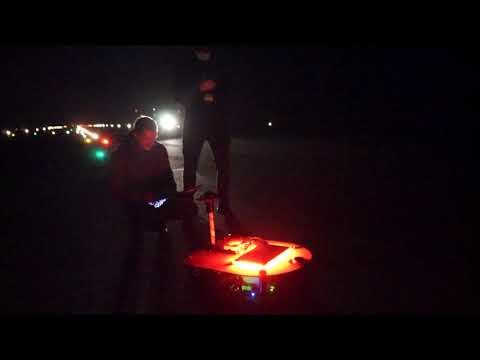
As seen in the Figure, the robot is designed as a prototype differential drive AMR platform. The AMR features an high power motor controller for two 600W wheel hub motors, and a selection of embedded computing hardware acting as a distributed system by using ROS (Robot Operating System) as a middleware. An Nvidia Jetson Nano representing the application control unit is able to process images from both a front and rear a camera at 20 Hz and therefore operating at the full frame rate of the cameras with a given shutter time of 50ms for the best possible raw image at night. Due to the known geometric relationships and the runway, which is assumed to be a plane, a mono camera pipeline is used. In order to be able to inspect both sides of the runway lighting in a single run, one camera each at the front and rear is used. Due to the width of the runway, approximately 60 meters, the widest available lens of 6mm is used. Camera models are UI-3070CPC-HQ Rev.2 and UI3140CPC-HQ Rev.2 from IDS. By taking the given measures into account, the minimal depth and angular resolution can be derived. Resulting in a maximum depth error of 15m and angular error requirement of 2.9°. For trajectory planning and state estimation, a Raspberry Pi 4 has been utilized as the autonomous control unit. An additional Raspberry Pi 4 is placed with a 3D time-of-flight sensor in the front end of the robot with embedded point cloud processing, acting as a safety precaution for the robot and surroundings. The second figure shows the proposed differential drive robot with integrated cameras and GNSS.
The IMU and GNSS devices experienced system-breaking electrical noise disruptions when the motor controllers were engaged in closed loop control mode. MK II presents design changes to counter those issues.
The process of detecting lights on the runway is split into two main steps:
- Position estimation: Images are taken from the camera and processed, contours of the lights are found and their centers are transformed via a homography matrix to relative meters in the robot's GNSS perspective, along with an uncertainty ellipsoid. Due to the positioning of the lights on the runway and their distance relative to one another (150 cm between lights situated on the same row, 3000 cm between rows of lights), this operation will be considered accurate if the estimation of the X coordinate has an error lower than 75 cm and the estimation of the Y coordinate has an error lower than 1500 cm.
- Database matching: The relative coordinates are converted to latitude and longitude coordinates by using the position given by the robot's GNSS, the estimated coordinates and uncertainty ellipsoid are used to match the light to it's correspondent in the local database.
The front and rear camera follow the same exact computer vision pipeline, ran in parallel on the robot's onboard computer.
After acquisition, the camera image is undistorted using a transformation matrix and distance coefficients obtained in a prior checkerboard camera calibration. Since the light inspection operation is performed at night when there is a low level of ambient light, lights can be distinguished from other elements in a grey-scale image due to their high pixel intensity. However, other lights than those on the runway can be present in an image, such as those from the airport buildings surrounding the runways. These lights appear mainly around and above the horizon line, while the lights of interest appear below the horizon as they are embedded in the ground. Additionally, lights on the runway appear increasingly close to each other and eventually have their contours merge, as they are farther away from the camera and closer to the vanishing point. To solve both issues, the image is cropped to a set height that allows for distinction between separate light contours and eliminates irrelevant lights, as seen in the follogwing Figure.

An intensity threshold is applied to the cropped image to remove any potential noise and reduce the image to black and white pixels only. This image binarization reduces the problem to finding the contours of the lights, in order to further calculate the coordinates of its center pixel. For this task, two of the most popular contour tracing and pixel clustering algorithms were tested for performance: the Suzuki contour tracing algorithm and the DBSCAN clustering algorithm. The Suzuki algorithm was chosen for this project's implementation as it outperformed the latter by 13.3ms in runtime while still detection all lights correctly. The pixel coordinates of the contour's center are transformed into relative meter camera coordinate frame with the use of a homography transformation. The homography transformation matrix was determined in a prior calibration of the computer vision setup by capturing an image of a rectangle of known real world dimensions and mapping it's corners to the corresponding pixel coordinates in the image. With 4 pairs of pixel-meters vertices, the 3x3 matrix is found by a process of Gaussian elimination.
![]()
Because this solution cannot directly obtain the perfect absolute position of a light in a non deterministic system such as a mobile robot, the algorithm also estimates the uncertainty by transforming the known uncertainty in image coordinates to the real world. This will result in an uncertainty ellipsoid which is used to associate light correctly. The homography transformation matrix is multiplied with the center pixel of the light's contours and it's uncertainty pixels as follows:
where and
are vertices in the ground and image plane respectively, and
is the homography transformation matrix. The light's relative meters position from the robot and uncertainty ellipsoid are then passed on to the next stage of light detection.
After successful detection and transformation of the light's relative meters position into a globally fixed coordinate frame, it is necessary to associate it with the database. The following figure visualizes this process.

When new measurements arrive, an association map is created with the globally known lights. Based on the positionalinaccuracy of the robot and the uncertainty of the light detection, an elliptical gating area is formed as shown in figure 6. Ambiguous associations are resolved by computing the association cost using the Mahalanobis distance and a nearest neighbour search. Due to the calculated statics of the light at the end it is possible to use this technique as long as the majority of associations are correct. After the correct association to the known map, the local database is updated with detected and expected detections.
The kinematic model employed is the differential drivem odel. The model consists of 2 drive wheels, which are sharing a common axis. Each wheel can be independently driven in both directions. With such a kinematic model robot can turn by varying the difference in velocities of the two wheels, as well as obtain a straight line trajectory, by setting equal velocities to both wheels.

The controller node controlling the robot’s wheels receives astandard ROS command velocity message, which consists of3 linear and 3 angular velocity valuesvx,vy,vz,ωx,ωy,ωz.The values are using the robot’s local coordinate frame. Afterreceiving velocities from the message, the node proceeds tocompute demanded angular velocity of the wheels. Given therobot’s velocityvrobin thexrobdirection, the angular velocityωrobaround thezaxis, the robot tire radiusrand the robotwheel track2R, the equations used to obtain angular velocityfor each wheel (ωl,ωr) are presented below
State estimation is an essential part of any mobile roboticapplication as it enables the robust operation of other systemcomponents, such as the trajectory control and runway lightassociation. Several sensors are fused to estimate the pose andvelocity of the ground robot. 7 shows the proposed architec-ture. With an output of the final pose in a locally consistentfixed frame, called map. To take advantage of redundancy instate estimation, the contribution of each sensor input to theoverall estimated state has to be quantified in function of thesensor’s accuracy and previous state knowledge. The ExtendedKalman Filter (EKF) is the state-of-the-art estimator for fast,mildly non-linear systems. For systems with white zero-meanadditive Gaussian noise corrupting the sensors and the processmodel, it is a good approximation of the optimal solution.

Madgwick’s algorithm is applicable to inertial measurement units (IMU) consisting of gyroscopes and accelerometerssensor arrays that also include magnetometers. It shows a 36% lower orientation standard deviation error then Kalman-basedapproaches. The algorithm uses a quaternion representation, This representation is numerically more efficient and required by the ROS common messages. Allowing accelerometer and magnetometer data to be used in an analytically derivedand optimised gradient descent algorithm to calculate the direction of the gyroscope measurement error as a quaternion derivative. The orientation is calculated by two main processes. In the first step gyroscope measurements are processed with a correction algorithm, which depends on the parameter ζ. To minimize the error caused by the bias and the drift, they are used to calculate the orientation with the quaternion propagation starting from the orientation estimated at the previous step. Afterwards the accelerometer and magnetometer measurements are fused with a tuning parameter β by the gradient descent algorithm. The output of the gradient descent algorithm is then used to correct the orientation estimated by considering only gyroscope measurements. In order to have reliable input for the Extended Kalman Filter the standard deviation of thefused 9-dof output is determined and set accordingly in the covariance matrices. The process model for the extended kalman filter used is driven by the accelerometer. The robot base frame is chosen to carry the IMU which is placed in the center of rotation which is represented by the middle point between both powered wheels. A constant velocity model is used with the accelerometer as an input to the system. Due to the application constraints of a mobile robot on an airport runway, it is known that the vehicle will remain flat on the ground and not be significantly tilted. This assumption simplifies the state to a 2D state with only 6 elements.
and
are the position and heading of the mobile robot platform represented in the map frame.
and
are the linear and angular velocities of the robot represented in it's the base frame.
is the measured acceleration, R(θ) the rotation matrix between the robot base frame and the fixed map frame.
andn
represent white noise. The robot platform is equippedwith multiple sensors which can be reduced to the quantitiesbeing measured: position
, heading zθ, velocity
, and yawrate
. For example the GNSS can be seen as an absolute position sensor. This holds only if it can be assumed that the noises of the decomposed measurements are uncorrelated.
The AMR and local information about the runway relies on a database of points of interest maintained apart from the robot. While the database and access are application specific, it is expected that many airports to use a similar method of cataloging their lights to ensure appropriate inspections in accordance with runway maintenance guidelines. A copy of the database is downloaded to the robot from the origin source,and updated on the local version until the robot has completed a full inspection. The database information is downloaded over a wireless 4G cellular network to provide higher flexibility; this same connection is also used for GNSS correction data. Certain critical information is necessary, and made available tothe other software on the robot. This includes the ID number of each light, model number, the WGS (World Geodesic System)coordinates of the light, and two extra fields added to the list by our method to provide an expected number of detections, and another to increment each time a valid detection is made. After the inspection is complete the number of times a light is seen is compared to the expected time to create a confidence score.
This confidence score is then compared to a set threshold for identification, if the light has been seen enough times that it can be reasonably verified to be in functioning condition, the status in the local database is updated. After each light’s score has been checked against this threshold, the lights that can be ascertained to be functioning are sent back to the master database with an update code and status matching that which would indicate the appropriate time and manner of inspection. By using this technique small measurement errors can be compensated and and ambiguities compensated as long as the majority is correct and the threshold value adjusted accordingly. Therefore creating a robust and completely autonomous inspection system without any human operator.
The proposed autonomous mobile robotic platform hasbeen validated from subsystem to system level. Furthermoreextensive tests on an actual airport have been conducted. The robot platform showed to be mechanically very stablewith vibration introduced angular velocities of mostly below 0.05 rad/s compared to more simple differential drive platformswith a critical x and y angular velocity of 5 rad/s. There theproposed platform is capable of capturing long exposed imageswhile driving in the night.
The following figure 8 shows the GNSS Measurements(blue) and estimated states in between (green) as well as theplanned path (yellow). It can be seen that the full state esti-mation by using the Madgwick orientation estimation together with the EKF to estimate the corrected pose is able provide alow error base line for the pure pursuit controller to accuratelyfollow the planned path. It shows an angular heading error of 1.5°. This test was conducted on the actual airport runwayincluding all local conditions.

Figure 9 shows the absolute light detection error as afunction of the distance to the light. The validation of the lightdetection was performed by comparing the values estimatedby the perception pipeline with known ground-truth values andcalculating the error between them. It can be seen that the errorstays way below the requirement of 15m while maintainingan angular error of 1.7°. Therefore resulting in a system errorlower than all initial requirements to accurately associate thelights correctly.

This presented paper presents a novel approach to au-tonomous runway light inspection. Obtained results show thatmodern mobile robots are capable of being employed in high-profile tasks. The proposed robotic platform can solve prob-lems related to manual inspection done by human operators,increasing safety and repeat-ability. The described perception algorithms together with implemented localization and naviga-tion stack proved to obtain sufficient light association accuracy. The robotic platform is flexible and can be used in differentconditions. Further research can be conducted, based on this work and therunway crack detection presented, to develop a complete airport infrastructure inspection platform, which fully auto-mates all inspections.
This work was partly supported by iLocator, Aarhus Airport,and Leica Geosystems.


The 3D Model of the robot can be found inside the hardware folder.
And ODrive 56V with a 48V LiIon battery is used in combination with the following wheel hub motors.


Install all dependencies:
git submodule update --init --recursive
rosdep install --from-paths src --ignore-src -r
Generate Path and correction data NEMA code https://nmeagen.org/
LEDs with Pi: https://learn.adafruit.com/neopixels-on-raspberry-pi/python-usage
Use catkin build instead of catkin_make: https://catkin-tools.readthedocs.io/en/latest/installing.html
Starting and Stopping the ueye camera usb service:
sudo systemctl start ueyeusbdrc.service
sudo systemctl stop ueyeusbdrc.service
roslaunch common perception.launch
roslaunch common gnss.launch
roslaunch common rtk.launch
roslaunch common state_estimation.launch
roslaunch ueye mono.launch
roslaunch ueye stereo.launch
sudo apt-get install ros-noetic-teleop-twist-keyboard

rosrun teleop_twist_keyboard teleop_twist_keyboard.py
Mono Camera:
rosbag record -a -x "/image_raw/theora(.*)|/image_raw/compressedDepth/(.*)|/image_raw/compressed(.*)"
Dual Camera:
rosbag record -a -x "/left/image_raw/theora(.*)|/left/image_raw/compressedDepth/(.*)|/left/image_raw/compressed(.*)|/right/image_raw/theora(.*)|/right/image_raw/compressedDepth/(.*)|/right/image_raw/compressed(.*)"
rosbag play TEST.bag -l /odometry/filtered:=/trash /odometry/filtered_map:=/trash2 /odometry/gps:=/trash3 /tf:=/trash4 /tf_static:=/trash5 /initialpose:=/trash6 /gps/filtered:=/trash7 /rosout:=/trash8 /rosout_agg:=/trash9 /diagnostics:=/trash10 /imu/data:=/imu/data_old /ublox_gps/fix:=/ublox_gps/fix_old /odrive_basic_node/twist_estimation:=/odrive_basic_node/twist_estimation_old -s 0 -l