What Are Flying Wings? Flying wings are a type of aircraft design that integrates the fuselage and wing into a single cohesive structure. This design eliminates the need for separate tail and fuselage components, making the aircraft more aerodynamically efficient. The entire airframe contributes to lift generation, leading to a unique blend of efficiency and performance.
Advantages
- Aerodynamic Efficiency: The seamless design reduces drag significantly, enhancing fuel efficiency and range.
- Structural Efficiency: Fewer components mean a lighter overall structure, which can contribute to better payload capacity relative to the aircraft's weight.
- Stealth Characteristics: The reduced radar cross-section of flying wings makes them advantageous for military applications.
Drawbacks
- Stability Challenges: The absence of a tail can lead to stability issues, particularly in pitch and yaw.
- Limited Space: The unique shape may limit internal volume for passengers or cargo.
- Design Complexity: Achieving a balanced design that incorporates stability, control, and efficiency is more complex than traditional configurations.
Design Details
Dimensions and Specifications
Design Details
• Dimensions and Specifications
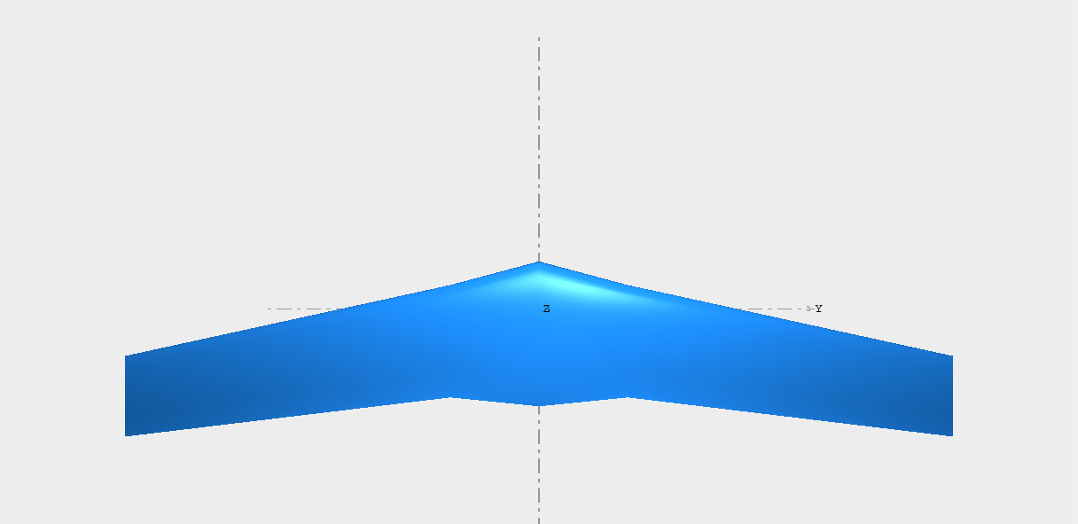
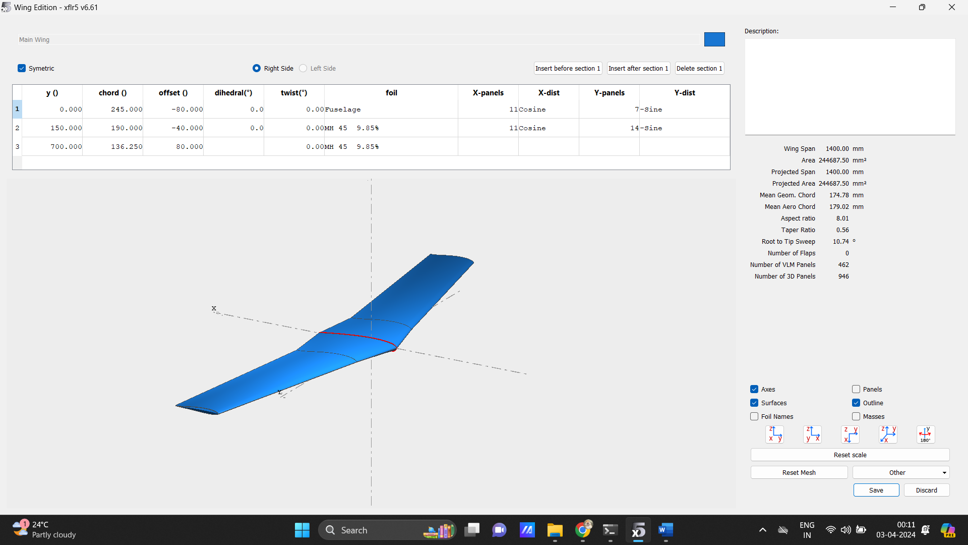
• Wingspan: 1400 mm
• Chord Length: Root chord 245mm , MAC- 179mm
• Wing Area: 244687 mm square
• Aspect Ratio: 8.010
• Weight: 1.767kg (glass fibre material)
Airfoil Selection
• Main Wing Airfoil: The MH49 airfoil is selected for the main wing. This airfoil is known for its excellent performance in terms of lift-to-drag ratio across a wide range of Reynolds numbers, making it particularly suited for use in efficient, long-range flying wing designs. Its characteristics support efficient cruise performance as well as good handling at lower speeds.
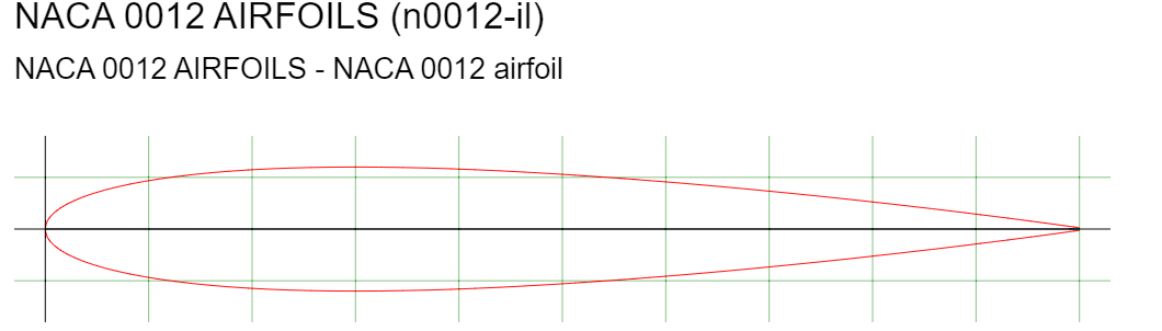
• Fuselage Airfoil: For the integrated fuselage section, the NACA 0012 airfoil is chosen. Given that flying wings blend the wing and fuselage into a single body, the NACA 0012 provides a robust, symmetrical profile that contributes to stability and helps manage the airflow over the body, especially at varying angles of attack.
• Wing Span: The model features a total wingspan of 1400 mm, suggesting a design that may offer efficient glide and stable flight characteristics.
• Chord Distribution: It starts with a root chord of 245 mm, tapering to 136.25 mm at the tip, which can help minimize induced drag and improve lift distribution across the span.
• Sweep: The wing sections are swept back, with offsets listed as -80 mm at the root and 80 mm at the tip, characteristic of designs intended to delay drag rise at higher speeds.
• Dihedral: Set uniformly at 0 degrees across all sections, indicating a neutral effect on lateral stability from dihedral angle, possibly relying on other design aspects for roll stability.
• Twist: No twist is indicated for any wing section, which is an unusual choice for flying wings and could suggest reliance on advanced control systems for stability management.
• Airfoil: A single airfoil type is employed across the span, identified as "9.85%", likely referencing the thickness-to-chord ratio. The selection of airfoil may be based on achieving specific aerodynamic qualities.
• Aspect Ratio: The aspect ratio is computed to be 8.01, indicative of an efficient design that seeks a compromise between maneuverability and cruising performance.
• Taper Ratio: With a value of 0.56, the wing shows a moderate taper, enhancing its aerodynamic efficiency and flight characteristics.
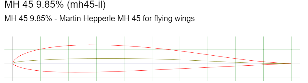
MH 49 Airfoil:
Developed by Martin Hepperle, the MH 49 is a laminar flow airfoil optimized for gliders and electric aircraft. It is designed to achieve high lift-to-drag ratios at low Reynolds numbers, making it efficient for slow to moderate speed flight regimes. The airfoil has a relatively thin profile and exhibits good performance in terms of both lift and resistance to stall. Ideal for use in the main wing of aircraft that require efficient cruise performance and good handling at low speeds, such as gliders, UAVs, and efficient, long-range flying wings.
NACA 0012 Airfoil:
A symmetrical airfoil developed by the National Advisory Committee for Aeronautics (NACA). It has no camber, which means it produces no lift at zero angle of attack, but it has a predictable stall behavior and generates lift equally well in both positive and negative angles of attack. Often used for fuselage design, especially in flying wings, as it provides consistent performance and can help manage the airflow over the body effectively. Its symmetrical nature and robust performance characteristics make it suitable for components where directional stability is essential, like vertical stabilizers, or where aerodynamic forces need to be balanced on both sides of the airfoil, such as in the fuselage of a flying wing.
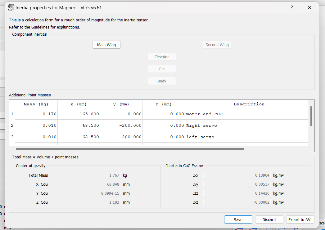
The weight distribution of the aircraft is a critical factor in its overall design and flight characteristics, impacting stability, control, and performance.
Analysis Type
Aerodynamic Analysis Report
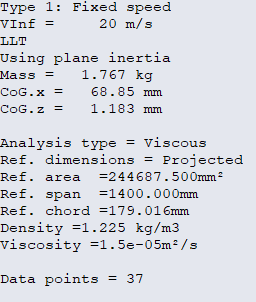
The aerodynamic performance of a model flying wing with MH49 airfoil for the main wing and NACA 0012 for the fuselage was analyzed at a fixed speed of 20 m/s, with the results obtained using the XFLR5 analysis software.
Analysis Conditions Type of Analysis: Viscous Reference Area: 244687.500 mm² Reference Span: 1400.000 mm Reference Chord: 179.016 mm Density: 1.225 kg/m³ Viscosity: 1.5e-5 m²/s
Aircraft Specifications Mass: 1.767 kg Center of Gravity (CoG): x: 68.85 mm z: 1.183 mm
Aerodynamic Coefficients and Stability
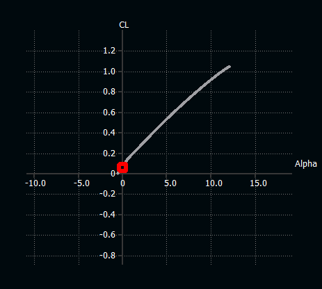
Lift Coefficient (CL) vs. Angle of Attack (Alpha) The CL vs. Alpha graph indicates a positive and linear relationship between the lift coefficient and the angle of attack up until the critical angle where the lift peaks before stalling. The maximum lift coefficient is achieved just before a stall, suggesting efficient lift generation capabilities of the wing at lower angles of attack.
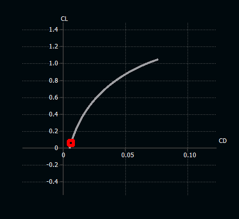
Drag Coefficient (CD) vs. Lift Coefficient (CL) The polar curve (CD vs. CL) shows a typical subsonic aerofoil performance with a gradual increase in drag as lift increases. The lowest drag per unit lift (best glide ratio) is identified at the point closest to the origin of the graph.
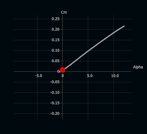
Moment Coefficient (Cm) vs. Angle of Attack (Alpha) The Cm vs. Alpha graph shows a stable and positive pitching moment, which grows with an increasing angle of attack. This indicates that the flying wing design might require an active control system to maintain pitch stability, especially at higher angles of attack.
Lift-to-Drag Ratio (CL/CD) vs. Angle of Attack (Alpha) The CL/CD ratio peaks at a moderate angle of attack, suggesting an optimal angle for cruise efficiency. The flying wing's design seems to offer an excellent glide performance, critical for efficient cruise and range.
Total Lift Coefficient Distribution The lift distribution across the span shows a typical elliptical pattern, which is indicative of efficient spanwise lift distribution and is often sought in wing design for minimizing induced drag.
Performance Parameters Estimated Efficiency: The flying wing shows a high theoretical efficiency (CL/CD ratio), which, in real-world applications, would contribute to reduced fuel consumption and extended range.
Conclusion
The flying wing model exhibits favorable aerodynamic characteristics, with a strong lift-to-drag ratio and efficient lift distribution. However, the increasing positive pitching moment with the angle of attack could indicate a tendency toward pitch instability that needs to be managed with careful design of control surfaces or an active control system. Further experimental validation is recommended to confirm these computational predictions and to fine-tune the design for optimal stability and control.