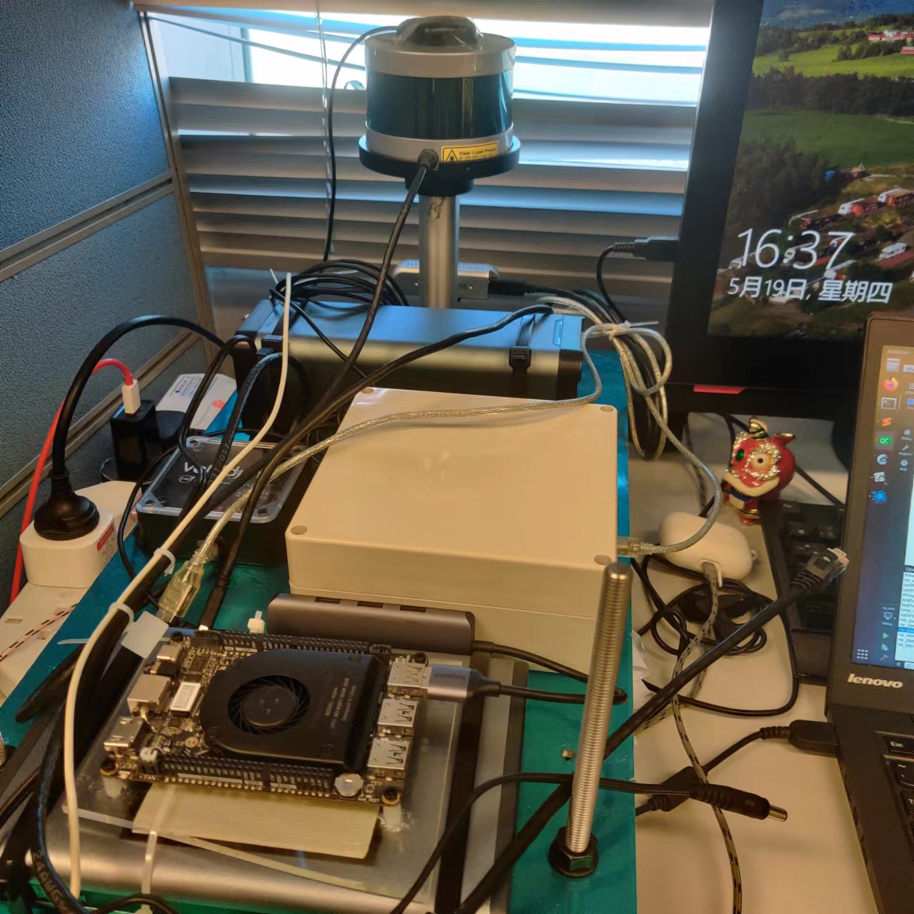
The aim of the project is to build a multi-sensor localization and mapping system. Its contents are related to the below toppics:
sensor assemblingsensor testingsychonization and calibrationdataset recordingmain code of the multi-sensorlocalization and mapping system
Four different sensors are utilized including:
GNSS receiverublox M8TIMUxsens-mti-g-710camerarealsense D435LidarVLP-16
xsens-mti-g-710 is a GNSS/IMU sensor, which can outpus both GNSS position and IMU data. realsense D435 is stereo camera, which can output one RGB image, two IR images and one depth image at the same time, but only one RGB or IR will be used in this project.
The above sensors are assembled on a aluminum plate by screws.
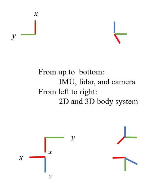
Their 2D(left) and 3D(right) body coordinate systems or are appoximate to:The ROS drivers of utilized sensors are installed and tested under the operation system Ubuntu 18.04 + ROS melodic.
There is also another ublox ROS driver maintained by KumarRobotics, which is more popular. The output topics from these two drivers are different, but both can be transferred to RINEX file easily. xsens-mti-g-710 can provide GNSS position, but its RAW GNSS measurments are not available, so ublox M8Tis utilized.
The calibration includes two parts:
time synchronizationspace calibaration
Only a coarse time synchronization is performed to sycn the time clock between the computer and GNSS by
sudo su
source /opt/ros/kinetic/setup.bash
source ${YOUR_CATKIN_WORKSPACE}/devel/setup.bash
rosrun ublox_driver sync_system_time
Next step is to use PPS from the GNSS receiver to trigger all other sensors.
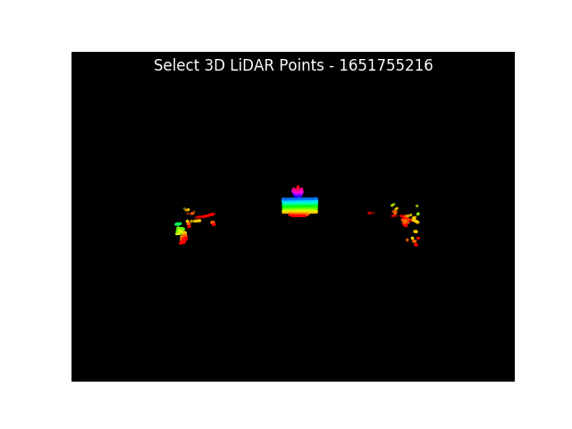
The space transformation between lidar and camera is computed by 3D-2D PnP algorithm implemented by heethesh. Two example pics of manually picking 2D pixls and 3D points are shown below.
The RMSE and transformation matrix:RMSE of the 3D-2D reprojection errors: 1.194 pixels.
T_cam_lidar:[
-0.05431967, -0.99849605, 0.0074169, 0.04265499,
0.06971394, -0.01120208, -0.99750413, -0.14234957,
0.99608701, -0.05366703, 0.07021759, -0.03513243,
0, 0, 0, 1]
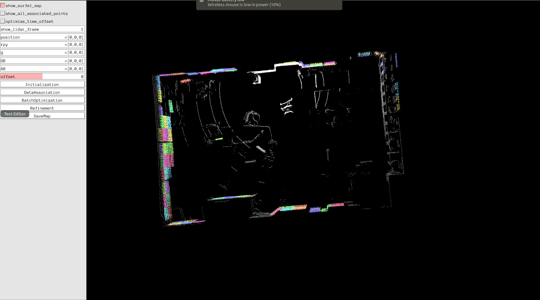
The The space transformation between lidar and IMU is computed by (a) hand-eye calibration and (b) batch optimization, implemented by APRIL-ZJU. One example calibration image is shown below.
The transformation matrix and time offest:
T_imu_lidar:[
-0.9935967, 0.1120969, -0.0141367, -0.276365,
-0.1121103, -0.9936957, 0.0001571, -0.0448481 ,
-0.0140300, 0.0017409, 0.9999000, 0.155901,
0, 0, 0, 1]
time offset: -0.015
Also, the intrtrinsic calibration parameters of the color camera inside realsense D435 is
height: 480
width: 640
distortion_model: "plumb_bob"
D: [0.128050, -0.258338, -0.000188, -0.000001, 0.000000]
K: [611.916727, 0.0, 322.654269, 0.0, 612.763638, 244.282743, 0.0, 0.0, 1.0]
The extrinsic matrix between IMU and camera is computed by:
T_imu_cam = T_imu_lidar * T_cam_lidar. inverse() =
[-0.0580613, -0.0564218,  -0.996717,  -0.316937,
  0.986113,  0.0187904,   0.165011, -0.0784387,
0.00643999,  -0.998402,   0.056142,  0.0154766,
         0,          0,          0,          1]
Before mounting the sensor platform on a real vehicle, I put it on a trolly to collect datasets with my laptop. The test dataset is stored on google drive. The scripts to collect the datasets are:
1. open one terminal to launch VLP-16
   source ${YOUR_CATKIN_WORKSPACE}/devel/setup.bash
   roslaunch velodyne_pointcloud VLP16_points.launch
2. open one terminal to launch realsense D435 camera
   source ${YOUR_CATKIN_WORKSPACE}/devel/setup.bash
   roslaunch realsense2_camera rs_camera.launch
3. open one terminal to launch xsens-mti-g-710
   source ${YOUR_CATKIN_WORKSPACE}/devel/setup.bash
   roslaunch xsens_mti_driver xsens_mti_node.launch
4. open one terminal to launch ublox M8T
   source ${YOUR_CATKIN_WORKSPACE}/devel/setup.bash
   roslaunch ublox_driver ublox_driver.launch
5. wait until the ublox output is stable and then sync time
   sudo su
   source /opt/ros/melodic/setup.bash
   source ${YOUR_CATKIN_WORKSPACE}/devel/setup.bash
   rosrun ublox_driver sync_system_time
6. use [rviz] or [rostopic echo] to check the relative messages, if all of them are valid,record the relative topics
   rosbag record /camera/color/image_raw /velodyne_points /gnss /filter/positionlla /filter/quaternion /imu/data /ublox_driver/ephem /ublox_driver/glo_ephem     /ublox_driver/iono_params /ublox_driver/range_meas /ublox_driver/receiver_lla /ublox_driver/receiver_pvt /ublox_driver/time_pulse_info
These topics are about:
/camera/color/image_rawis the color image data fromrealsense D435./velodyne_pointsis the lidar points fromVLP-16./imu/datais the imu data fromxsens-mti-g-710/gnssis the GNSS output fromxsens-mti-g-710/filter/positionllais the filtered position fromxsens-mti-g-710/filter/quaternionis the filtered quaternion fromxsens-mti-g-710- others are from
ublox M8T
The implementation is based on KITTI dataset. Need to be adapted to self-collected dataset.


