Original code forked from https://github.com/apachiww/hd44780_for_sdcc_51. Quoting: "(a library) suitable for 8051 based MCUs with various crystals and instruction cycles (1T, 6T, 12T) as AUTOMATIC delay calculation is available."
The original repository aimed to be a common library for many different LCD displays (0801, 0802, 1601, 1602, 2004, Noritake CU20045). This fork focus on specific LCD circuit modules, e.g.:
- The LCD 1602A (16 cols / 2 rows), version 3.0, with 4/8 bit interface.
- The LCD 1602A (16 cols / 2 rows), version 3.0, with I2C interface.
- The LCD 2004A (20 cols / 4 rows), version 1.3, with I2C interface.
There is little to no modification in the original source code. The actual purpose of this fork is to:
- Provide more testing (particularly the LCD initialization delay functions).
- Validate different hardware interfaces (4 bits, 8 bits and I2C communication).
- Offer better build and deploy automation, using avrdude (via Make) or flash programmers.
- Offer better structured header and source files, so there is no need to manually copy the source file for the different interfaces.
- Provide PCB schematics to build 8051-based development boards (TBD - in another git repository).
Projects were tested on an Atmel AT89S51, although others are theoretically supported - see conf/AT89S5x.conf. A configuration using an external EEPROM was set to test possible performance impact in the LCD initialization delay functions.
This circuit is an example of LCD 1602A 4 bit interface.
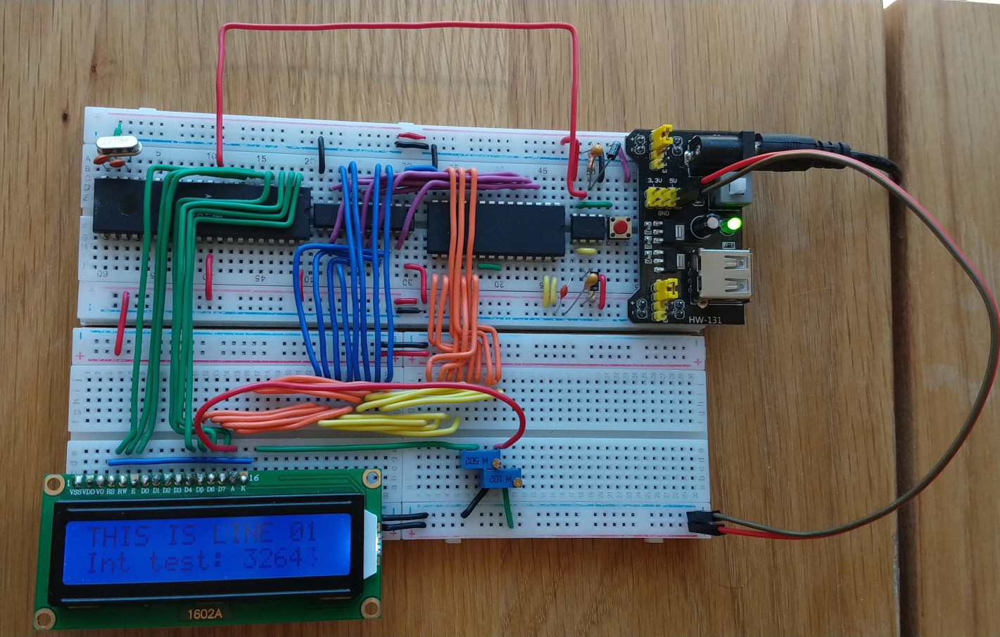
Obs: Although the SN74LS373 and EEPROM chips, together with the data/address multiplexed bus cables (orange, yellow, blue and purple wires) show on the board, notice that the MCU is reading instructions from its internal flash memory (EA pin is connected to VCC).
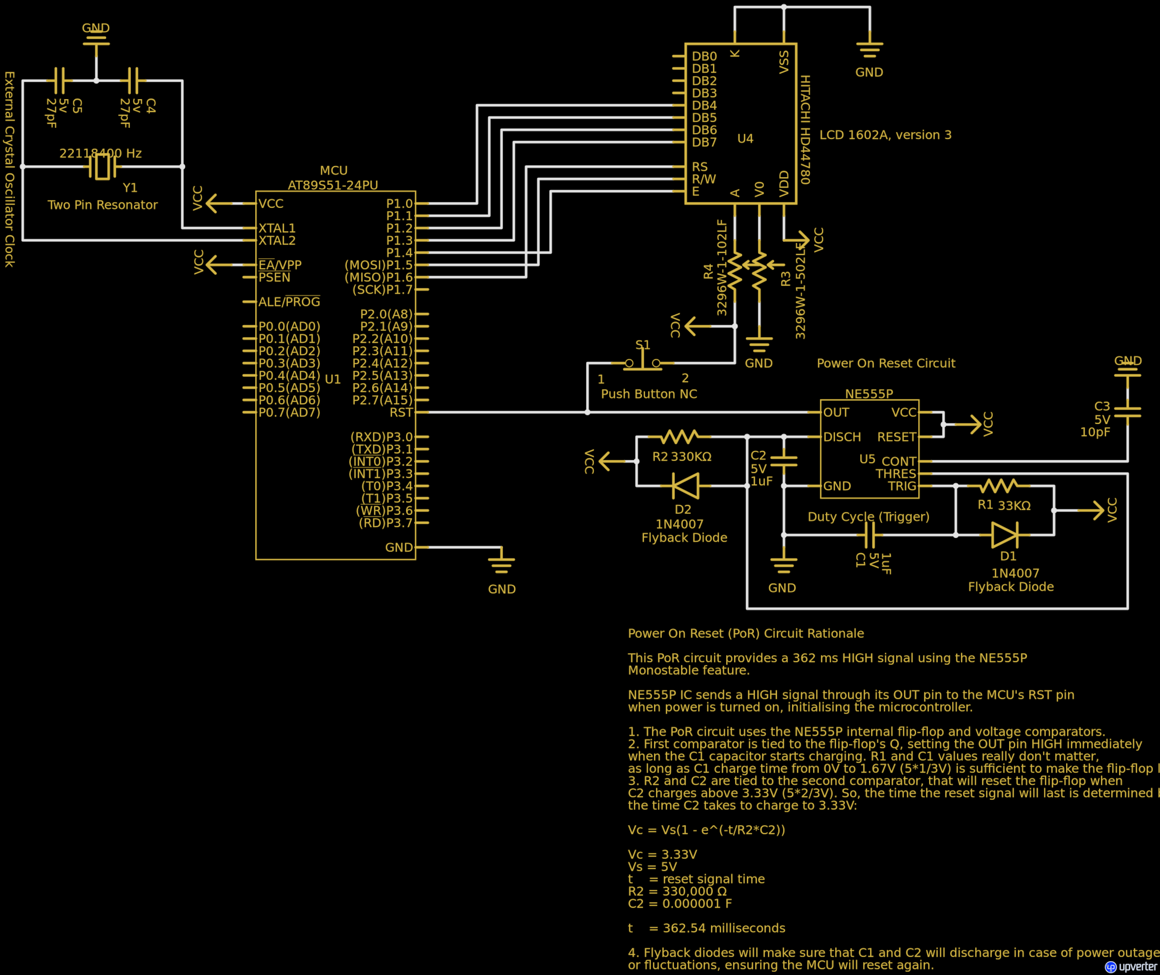
Available at https://upverter.com/design/mpeschke/1d90df03c47b8130/at89s51-hd44780-4bits/
Usage:
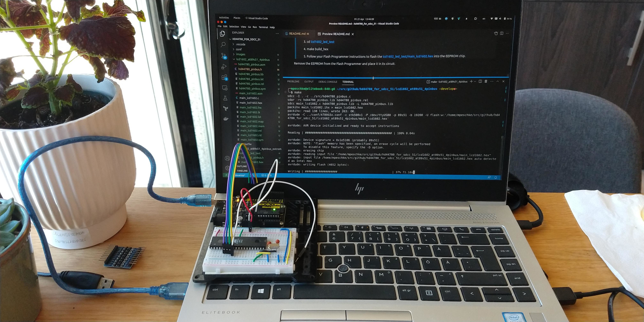
Get your hands on a AVRISP capable of flashing hex files to a AT89S51 microcontroller. There are several tutorials out there, the most popular are the ones using Arduino.
Place the microcontroller on the AVRISP board (follow instructions until 02:47).
Edit lcd1602_at89s51_4pinbus/Makefile to have your USB port in the
usb_portvariable.From a terminal, run the commands:
make
The make command will:
build the source code.
flash the HEX file into the microcontroller's flash memory.
Remove the microcontroller from the AVRISP board and place it in its circuit.
This circuit is an example of LCD 1602A 4 bit interface, but code is accessed from an external EEPROM.
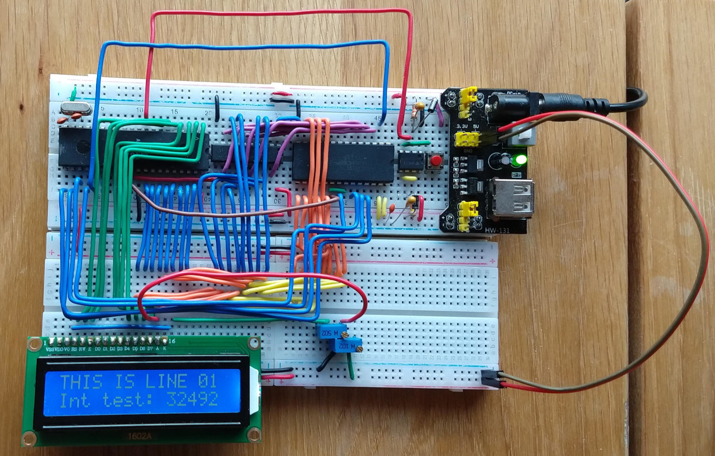
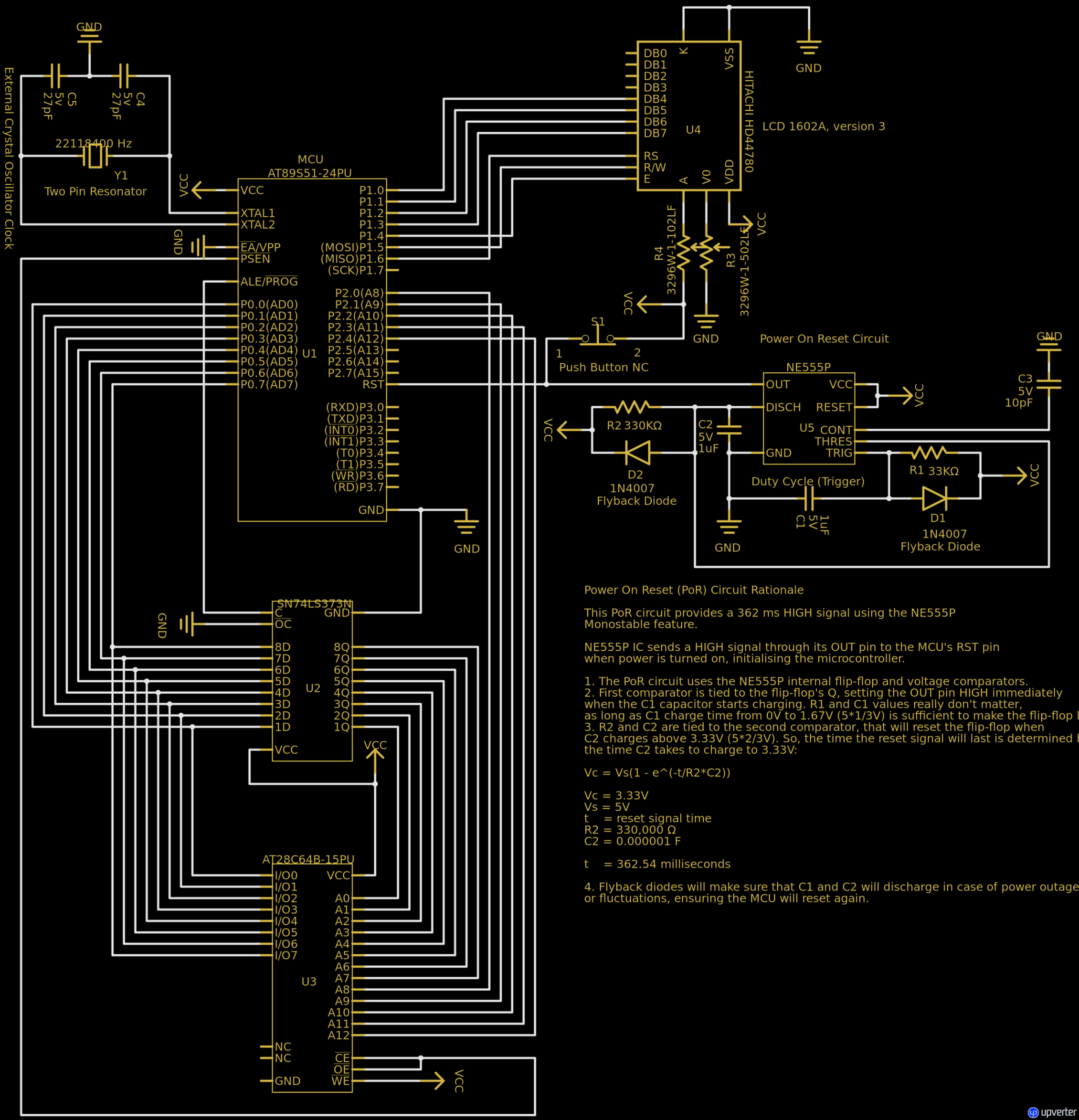
Available at https://upverter.com/design/mpeschke/917442ed3dc5514a/at89s51-hd44780-4bits-ext-eeprom/
Usage:
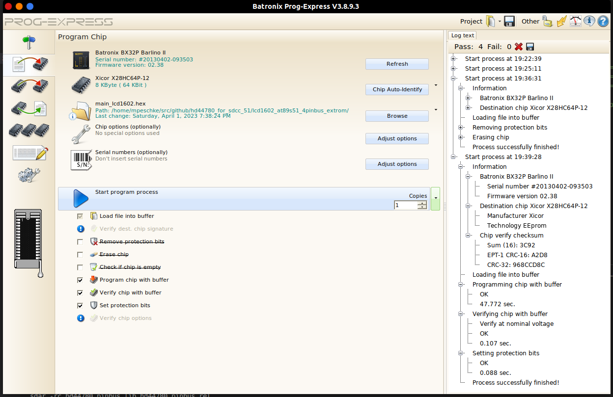
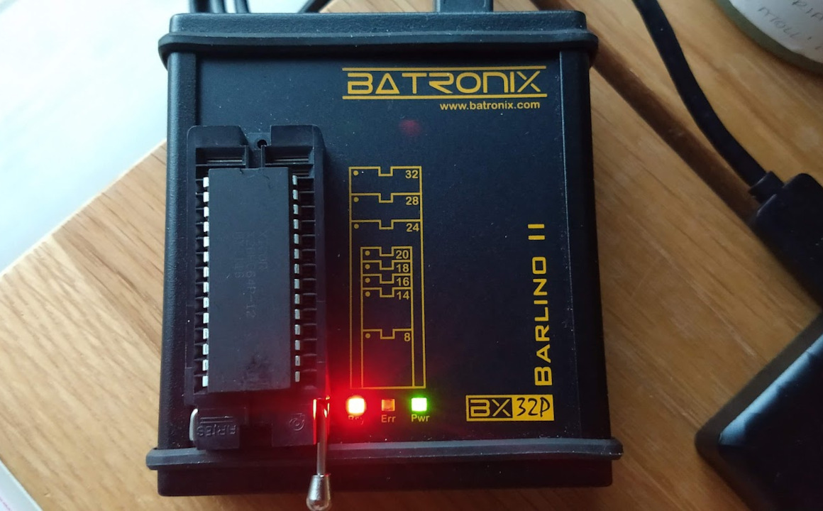
Get your hands on a Flash Programmer. The Batronix Barlino II was used for this project.
From a terminal, run the commands:
make build_hex
Follow your Flash Programmer instructions to flash the lcd1602_at89s51_4pinbus_extrom/main_lcd1602.hex into the EEPROM chip.
Remove the EEPROM from the Flash Programmer and place it in its circuit.
This circuit is an example of LCD 1602A I2C interface, but code is accessed from an external EEPROM.
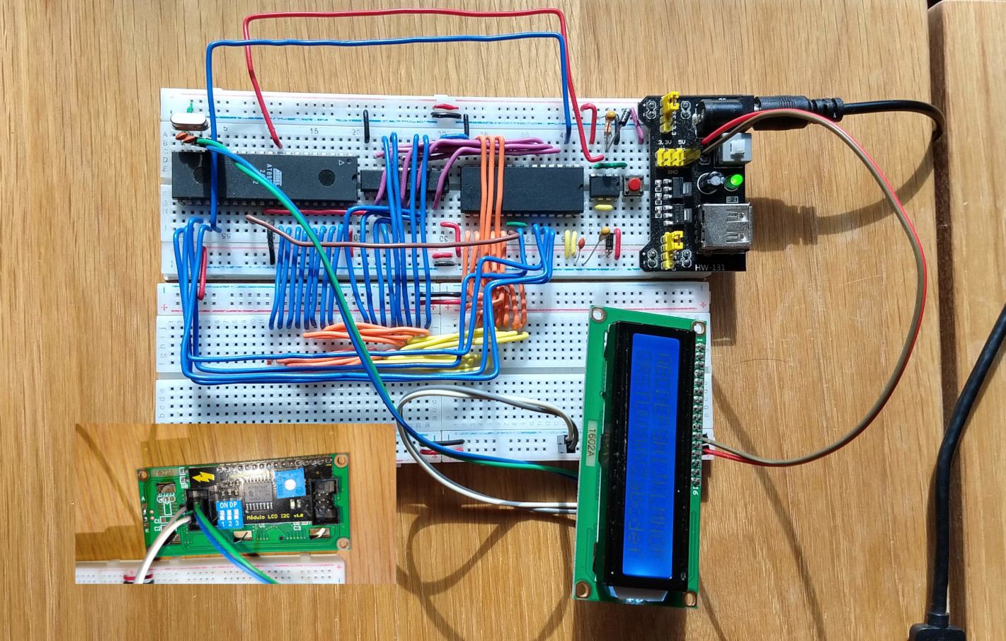
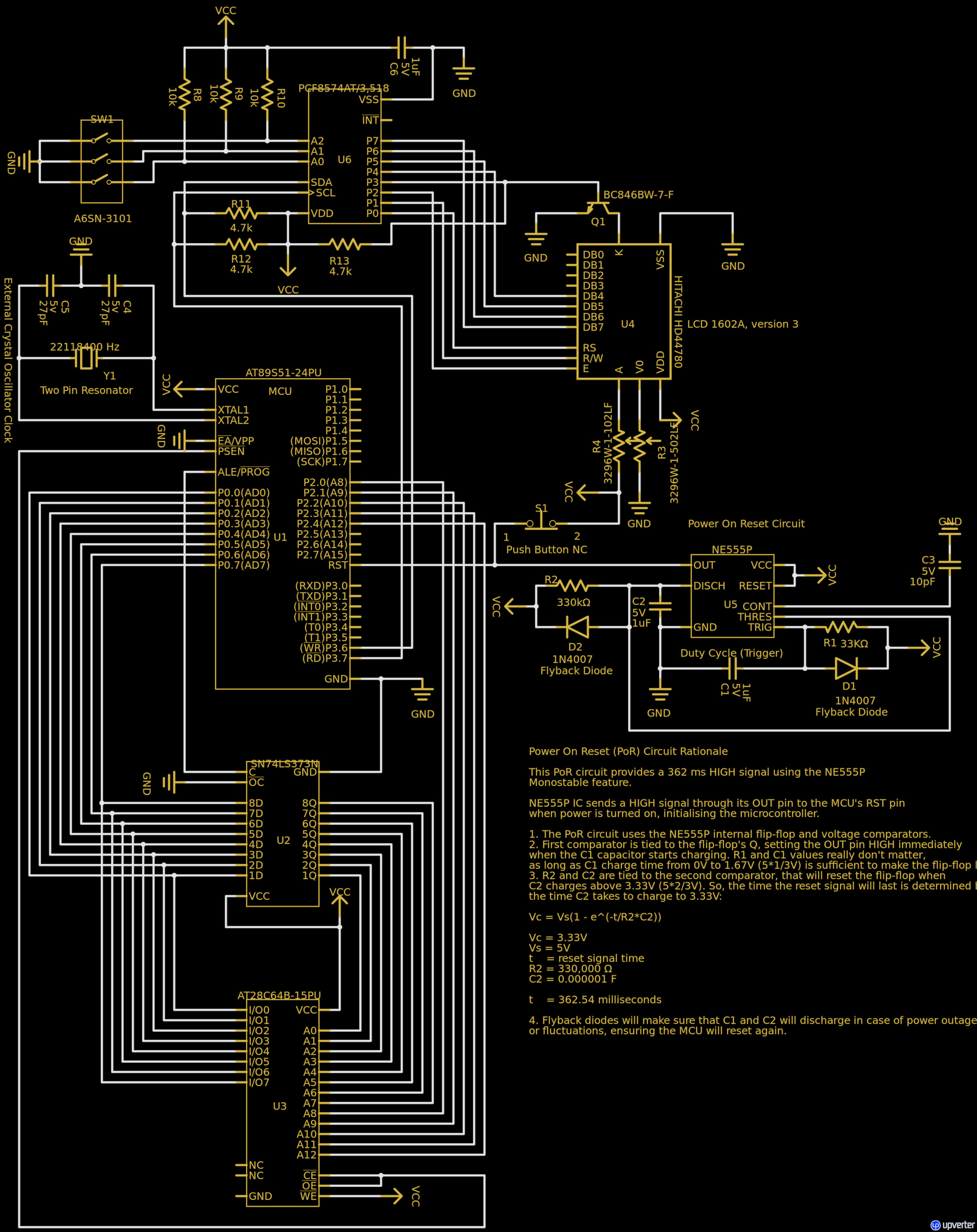
Available at https://upverter.com/design/mpeschke/b59b54c142cb2a9b/at89s51-hd44780-i2c/
Usage:
Get your hands on a Flash Programmer. The Batronix Barlino II was used for this project.
From a terminal, run the commands:
make build_hex
Follow your Flash Programmer instructions to flash the lcd1602_at89s51_i2c/main_lcd1602.hex into the EEPROM chip.
Remove the EEPROM from the Flash Programmer and place it in its circuit.
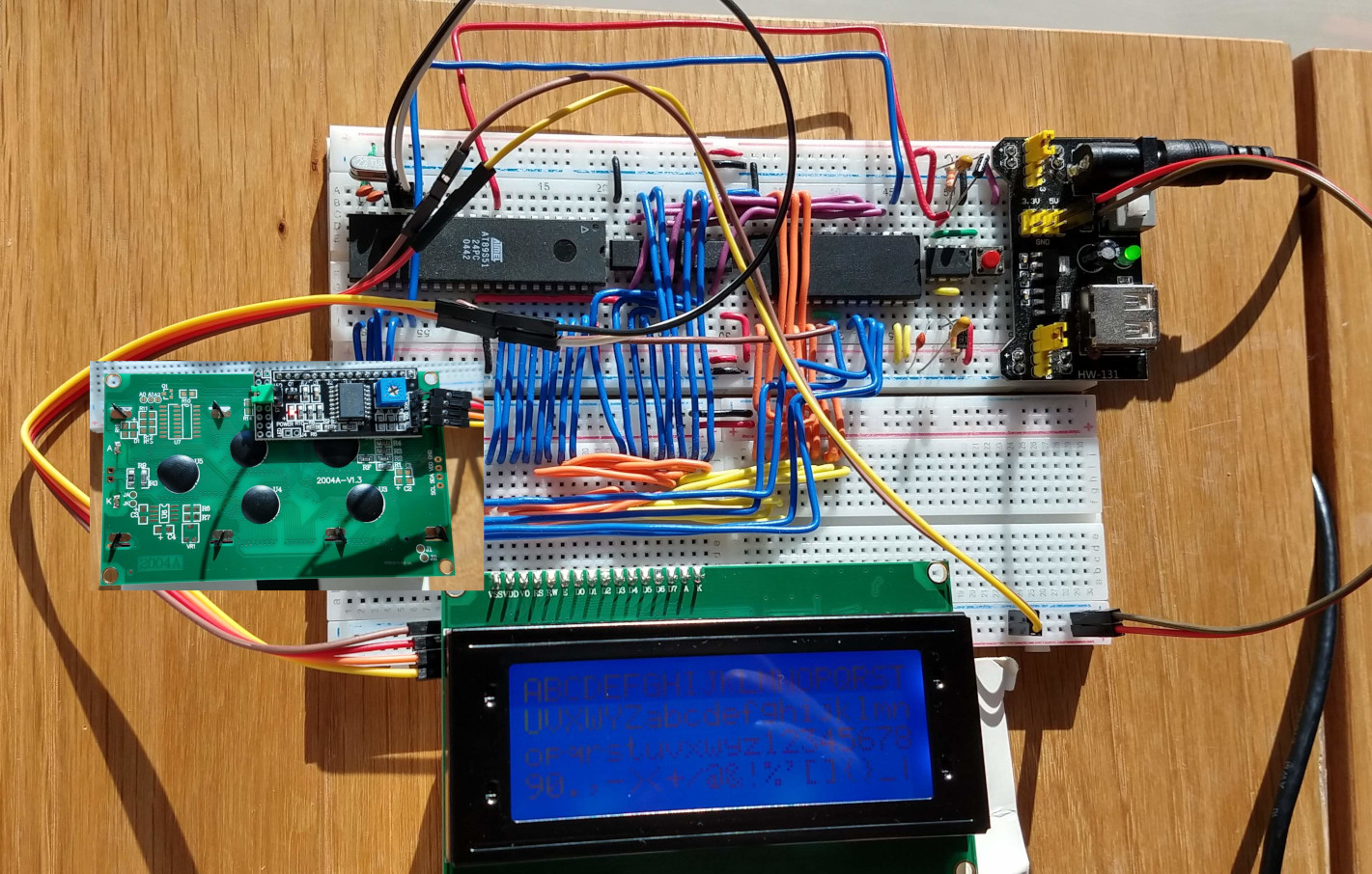
This circuit is an example of LCD 2004A I2C interface, but code is accessed from an external EEPROM.
Schematics and pin out are identical to the 1602 circuit, as both offer the same I2C interface.
Usage:
Get your hands on a Flash Programmer. The Batronix Barlino II was used for this project.
From a terminal, run the commands:
make build_hex
Follow your Flash Programmer instructions to flash the lcd2004_at89s51_i2c/main_lcd2004.hex into the EEPROM chip.
Remove the EEPROM from the Flash Programmer and place it in its circuit.
This circuit visually validates the LCD initialization delay functions. A blinking LED on microcontroller's port P1_5 in a 1 (one) second interval, using a 12 MHz crystal oscillator.
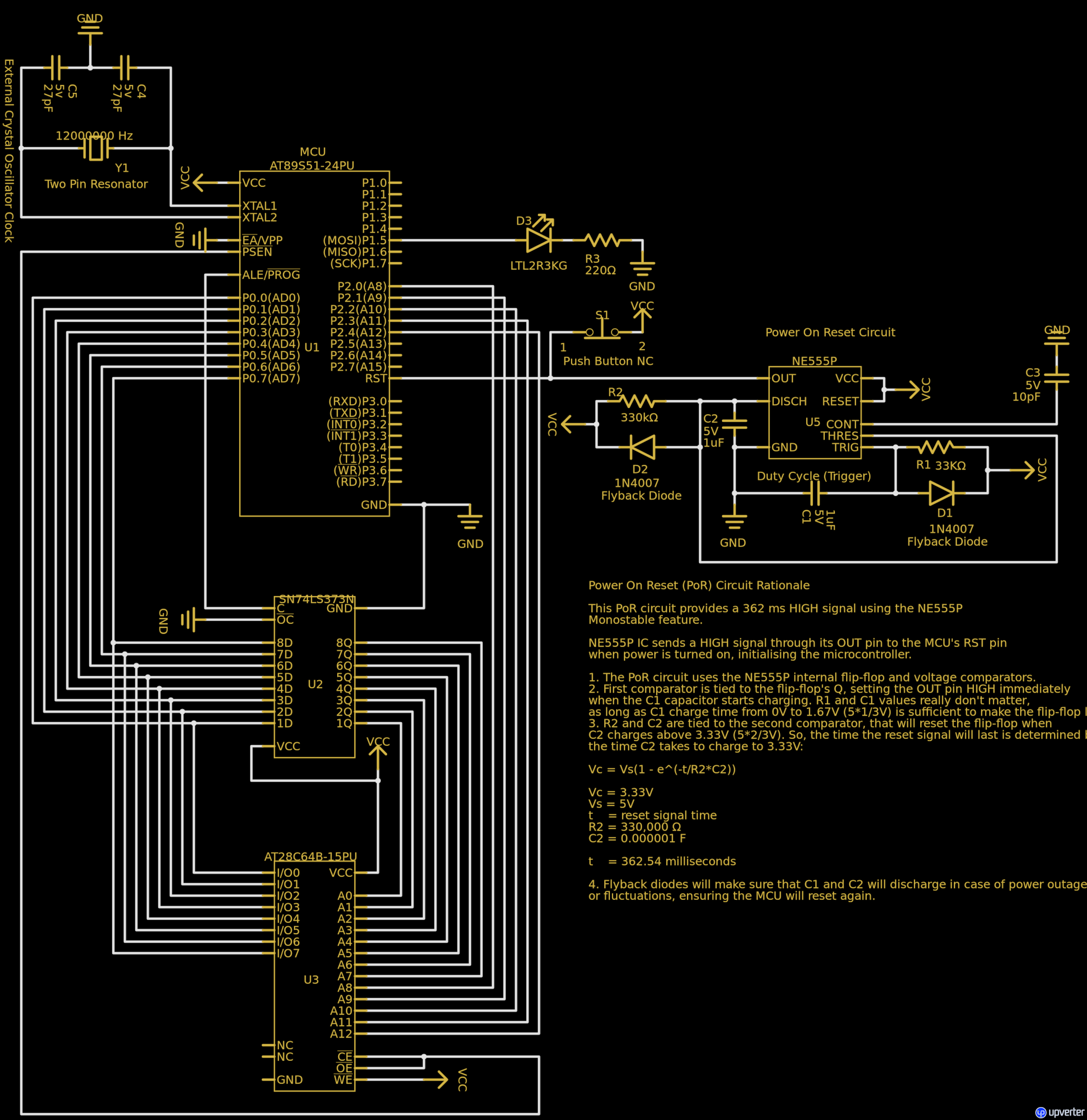
Available at https://upverter.com/design/mpeschke/6ed6139609f5693d/at89s51-hd44780-led-test-ext-eeprom/
Usage:
Get your hands on a Flash Programmer. The Batronix Barlino II was used for this project.
From a terminal, run the commands:
make build_hex
Follow your Flash Programmer instructions to flash the lcd1602_led_test/main_lcd1602.hex into the EEPROM chip.
Remove the EEPROM from the Flash Programmer and place it in its circuit.
