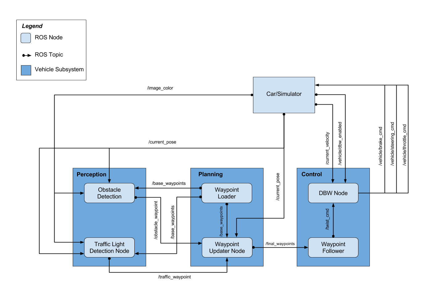
Note: For this project, the obstacle detection node is not implemented

This subsystem processes data from sensors and cameras into structured information that can eventually be used for path planning or control. In this project, we'll implement the traffic light detection node.
This node subscribed to four topics:
- /base_waypoints : The complete list of waypoints for the course.
- /current_pose : The vehicle's location.
- /image_color : Images from the vehicle's camera.
- /vehicle/traffic_lights : The coordinates of all traffic lights.
And the node will publish the index of the waypoint for nearest upcoming red light's stop line to the /traffic_waypoint topic. Then the Waypoint Updater Node uses this information to determine if the car should slow down to safely stop at upcoming red lights.
For the traffic light detection I've used the COCO-trained models from TensorFlow Object Detection API. The COCO-Trained models was pre-trained on COCO dataset that contains 90 classes of images and the index for traffic light is 10. Since the COCO dataset include the traffic light detection, I used a lightweight pre-trained model : ssd_mobilenet_v1_coco that is based on Single Shot Multibox Detection (SSD), the running speed was fast and the detection accuracy was pretty good in the simulator, which is suitable for this project.
To train a model based on ssd_mobilenet_v1_coco, I collected total of 1056 images from the simulator, and used 856 images as training dataset, 200 images as test dataset, then utilized LabelImg to manually label all the images. After labelling all the images, LabelImg will create xml file for each image, and we need to convert those xml files to two tfrecord files, one is the training data, the other is the test data. The COCO pre-trained model uses 90 classes of images, but in this project we only care about red light, yellow light, and green light, so we create a label map that only contains 3 classes(Red, Yellow, and Green). Finally, modified some variables in the config file of ssd_mobilenet_v1_coco model and trained the model for 20000 steps.
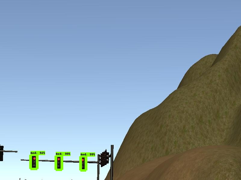
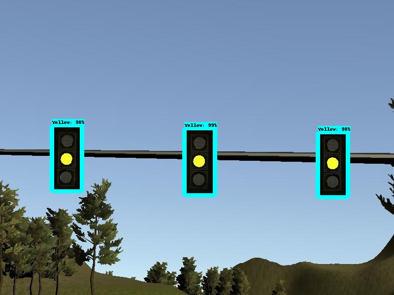
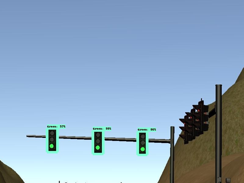
Here are some output images:
Once data from the sensors has been processed by the preception subsystem, the vehicle can use that information to plan its path. In this project we'll implement the waypoint updater node.
The eventual purpose of this node is to publish a fixed number of waypoints ahead of the vehicle with the correct target velocities, depending on traffic lights. This node subscribed to three topics:
- /base_waypoints : The complete list of waypoints for the course.
- /current_pose : The vehicle's location.
- /traffic_waypoint : The index of the waypoint for nearest upcoming red light's stop line.
And this node will publish a list of waypoints to /final_waypoints topic, each waypoint contains a position on the map and a target velocity.
The first waypoint in the list published to /final_waypoints topic should be the first waypoint that is currently ahead of our vehicle. To find the first waypoint, I've used the KD tree to find the closest waypoint to our vehicle’s current position and build a list containing the next 80 waypoints. Next, I subscribed to /traffic_waypoint topic, to see if there is any upcoming red traffic light. If there is any upcoming red light, I adjusted the target velocities for the waypoints leading up to red traffic light in order to bring the vehicle to a smooth and full stop at the red light's stop line.
To perform a smooth deceleration, I calculated the distance between vehicle's current position and stop line's position, then use square root of that distance as waypoint's velocity. As we get closer to the stop line, the distance will be smaller, and the velocity will decrease as well. When the distance is smaller than 1, I just set the velocity to 0.
This subsystem contains software components to ensure that the vehicle follows the path specified by the planning subsystem. In this project we'll implement the DBW(Drive By wire) Node.
Once messages are being published to /final_waypoints, the vehicle's waypoint follower will publish twist commands to the /twist_cmd topic. The goal for this node is to implement the drive-by-wire node which will subscribe to three topics:
- /vehicle/dbw_enabled : The DBW status. Since a safety driver may take control of the car during testing, we shouldn't assume that the car is always following our commands.
- /twist_cmd : Target vehicle linear and angular velocities in the form of twist commands.
- /current_velocity : A linear velocity of vehicle in m/s.
And use various controllers to provide appropriate throttle, brake, and steering commands. These commands can then be published to the following topics:
- /vehicle/throttle_cmd : shoulg be in the range 0 to 1.
- /vehicle/brake_cmd : should be in units of torque(N*m).
- /vehicle/steering_cmd : should be in the range -8 to 8.
At this point we have a linear and angular velocity and must adjust the vehicle’s controls accordingly. In this project we control 3 things: throttle, steering, brakes. As such, we have 3 distinct controllers to interface with the vehicle.
The throttle controller is a simple PID controller that uses the difference between current velocity (velocity that was been filtered out all of the high-frequency noise.) and target velocity (velocity that's coming in over the message) as the velocity error, and PID controller will adjust the throttle accordingly.
This controller translates the linear and angular velocities into a steering angle based on the vehicle’s steering ratio and wheel base. The steering angle computed by the controller is also passed through a low pass filter to filter out all of the high-frequency noise in velocity data.
First, if the target velocity is 0, and current is less than 0.1, that means the vehicle is really slow, and we should probably be trying to stop, so I just set the throttle value to 0 and the brake torque to 700(N*m) to stop the vehicle. Or if the throttle value is really small(less than 0.1), and the velocity error is less than 0, in this case, the velocity error is negative, which means that the vehicle is going faster than we want to be, so we will need to deceleration. I calculated the brake torque by multipling the following three variables : vehicle mass, wheel radius, and deceleration(the amount that we want to decelerate).
Please use one of the two installation options, either native or docker installation.
-
Be sure that your workstation is running Ubuntu 16.04 Xenial Xerus or Ubuntu 14.04 Trusty Tahir. Ubuntu downloads can be found here.
-
If using a Virtual Machine to install Ubuntu, use the following configuration as minimum:
- 2 CPU
- 2 GB system memory
- 25 GB of free hard drive space
The Udacity provided virtual machine has ROS and Dataspeed DBW already installed, so you can skip the next two steps if you are using this.
-
Follow these instructions to install ROS
- ROS Kinetic if you have Ubuntu 16.04.
- ROS Indigo if you have Ubuntu 14.04.
-
- Use this option to install the SDK on a workstation that already has ROS installed: One Line SDK Install (binary)
-
Download the Udacity Simulator.
Build the docker container
docker build . -t capstoneRun the docker file
docker run -p 4567:4567 -v $PWD:/capstone -v /tmp/log:/root/.ros/ --rm -it capstoneTo set up port forwarding, please refer to the "uWebSocketIO Starter Guide" found in the classroom (see Extended Kalman Filter Project lesson).
- Clone the project repository
git clone https://github.com/hankkkwu/SDCND-Capstone_project.git- Install python dependencies
cd CarND-Capstone
pip install -r requirements.txt- Make and run styx
cd ros
catkin_make
source devel/setup.sh
roslaunch launch/styx.launch- Run the simulator
- Download training bag that was recorded on the Udacity self-driving car.
- Unzip the file
unzip traffic_light_bag_file.zip- Play the bag file
rosbag play -l traffic_light_bag_file/traffic_light_training.bag- Launch your project in site mode
cd CarND-Capstone/ros
roslaunch launch/site.launch- Confirm that traffic light detection works on real life images
Outside of requirements.txt, here is information on other driver/library versions used in the simulator and Carla:
Specific to these libraries, the simulator grader and Carla use the following:
| Simulator | Carla | |
|---|---|---|
| Nvidia driver | 384.130 | 384.130 |
| CUDA | 8.0.61 | 8.0.61 |
| cuDNN | 6.0.21 | 6.0.21 |
| TensorRT | N/A | N/A |
| OpenCV | 3.2.0-dev | 2.4.8 |
| OpenMP | N/A | N/A |
We are working on a fix to line up the OpenCV versions between the two.


