This is a repository containing all the simulations and reports of CSE-306 Computer Architecture Sessional.
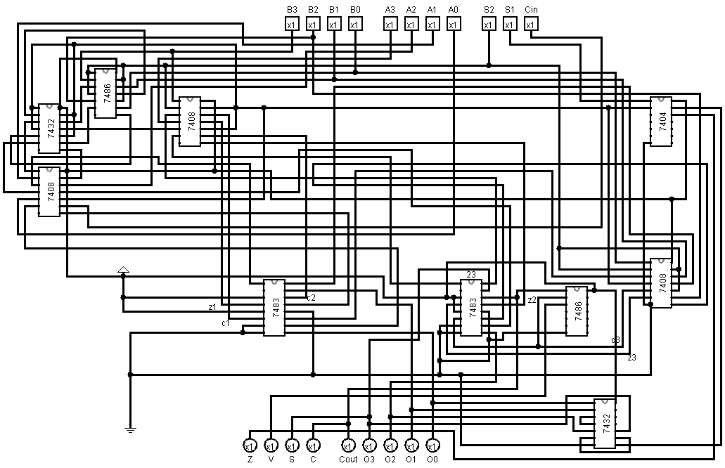
This ALU contains:
- Two 4 bit inputs A and B
- Three select bits S2, S1, S0 as ALU opcodes
- One 4 bit output
- Four flags: Z (Zero), C (Carry), O (Overflow), N (Negative)
| ALU opcodes | Functions | ||
|---|---|---|---|
| S2 | S1 | S0 (Cin) | |
| 0 | 0 | 0 | Transfer A |
| 0 | 0 | 1 | Increment A |
| 0 | 1 | X | AND |
| 1 | 0 | 0 | Add |
| 1 | 0 | 1 | Add with carry |
| 1 | 1 | X | OR |
| ALU opcodes | Required outputs | Adder inputs | Functions | ||||
|---|---|---|---|---|---|---|---|
| S2 | S1 | S0 (Cin) | Xi | Yi | Zi | ||
| 0 | 0 | 0 | A | Ai | 0 | Ci | Transfer A |
| 0 | 0 | 1 | A + 1 | Increment A | |||
| 0 | 1 | 0 | A ^ B | AiBi | 0 | 0 | AND |
| 0 | 1 | 1 | |||||
| 1 | 0 | 0 | A + B | Ai | Bi | Ci | Add |
| 1 | 0 | 1 | A + B + 1 | Add with carry | |||
| 1 | 1 | 0 | A OR B | AiBi' | Bi | 0 | OR |
| 1 | 1 | 1 | |||||
Xi = A(S1' + S2 XOR B)
Yi = S2B
Zi = S1'Ci
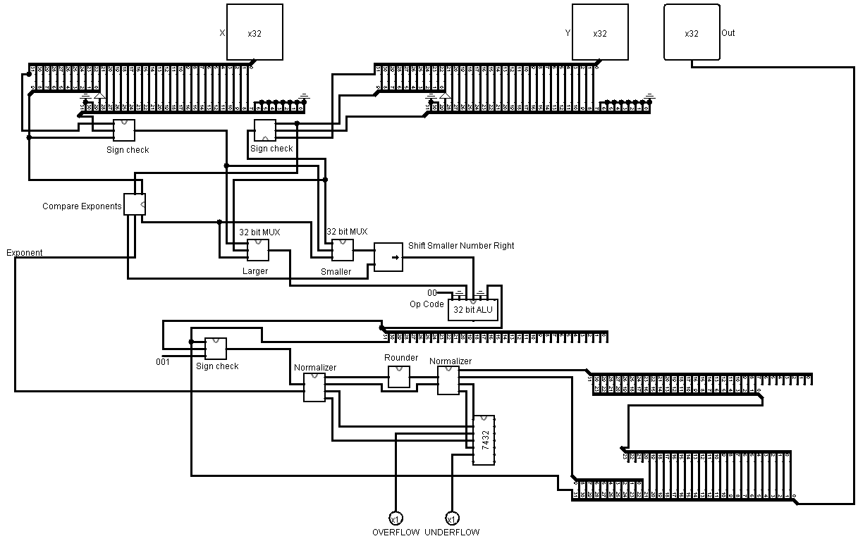
The adder takes two 32 bit floating point numbers and adds them together. The numbers are represented in the following format:
| Sign | Exponent | Fraction |
|---|---|---|
| 1 bit | 10 bits | 21 bits (Lowest bits) |
The numbers are in normalized form. There are two flags U (underflow) and O (overflow) which are set if the result is too small or too large to be represented in the format.
- Sign check: Checks if a 32 floating point number is positive, negative or the exponent is zero. If the number is positive then the output is the same as input. If the number is negative then it outputs the two's complement of the input. And if the exponent is zero then the output is zero.
- Normalizer: Normalizes a floating point number. But if the number is overflowed or underflowed while trying to normalize then the appropriate flags are set.
- Rounder: Rounds the 32 bit significand to 21 bits.
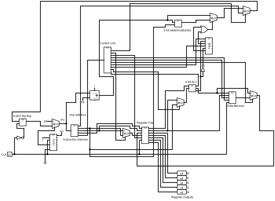
Write a valid MIPS assembly code and compile the code with MIPS-assembler. Now open the MIPS-simulator with logisim 2.7.1 Then open the machine.txt file (generated after runnig the C++ code) from the instruction memory.
- R-type:
| Opcode | Src Reg 1 | Src Reg 2 | Dst Reg |
|---|---|---|---|
| 4-bits | 4-bits | 4-bits | 4-bits |
- S-type:
| Opcode | Src Reg 1 | Dst Reg | Shamt |
|---|---|---|---|
| 4-bits | 4-bits | 4-bits | 4-bits |
- I-type:
| Opcode | Src Reg 1 | Src Reg 2/Dst Reg | Addr./Immdt |
|---|---|---|---|
| 4-bits | 4-bits | 4-bits | 4-bits |
- J-type:
| Opcode | Target Jump Address | 0 | |
|---|---|---|---|
| 4-bits | 8-bits | 4-bits | |
| Instruction Opcode | Instruction | MIPS Instruction Format | Instruction Type |
|---|---|---|---|
| 0000 | sub | R | Arithmetic |
| 0001 | ori | I | Logic |
| 0010 | bneq | I | Control |
| 0011 | addi | I | Arithmetic |
| 0100 | beq | I | Control |
| 0101 | or | R | Logic |
| 0110 | sw | I | Memory |
| 0111 | srl | S | Logic |
| 1000 | and | R | Logic |
| 1001 | andi | I | Logic |
| 1010 | lw | I | Memory |
| 1011 | add | R | Arithmetic |
| 1100 | sll | S | Logic |
| 1101 | subi | I | Arithmetic |
| 1110 | j | J | Control |
| 1111 | nor | R | Logic |


