This is an unofficial solution for eth zurich ros 2021 course for MLDA Robotics. The solution has been well tested for both ROS Melodic and Noetic.
The main solution package created for this is the smb_highlevel_controller which was created with the following command:
catkin_create_pkg smb_highlevel_controller
As the exercise requires the use of ROS in gazebo simulation, it is assumed that the computer is properly setup with ros-melodic-desktop-full or ros-noetic-desktop-full installation. Once ROS is installed, you can run the following command to create a Catkin workspace:
sudo apt-get install python3-catkin-tools
mkdir -p catkin_ws/src
cd ~/catkin_ws
catkin build

# Automatically source setup.bash for convenience.
echo "source ~/catkin_ws/devel/setup.bash" >> ~/.bashrc
source ~/.bashrc
This ROS stack requires some dependencies which can be installed with the following command:
sudo apt install -y ros-<distro>-hector-gazebo-plugins \
                    ros-<distro>-velodyne \
                    ros-<distro>-velodyne-description \
                    ros-<distro>-velodyne-gazebo-plugins \
                    ros-<distro>-pointcloud-to-laserscan \
                    ros-<distro>-twist-mux
where <distro> can be either melodic or noetic.
Once everything is fully setup, you can clone the package into the catkin_ws/src directory and build the entire package:
cd ~/catkin_ws/src
git clone https://github.com/NelsenEW/eth-zurich-solution
cd ..
catkin buildThis exercise is based on lecture 1.
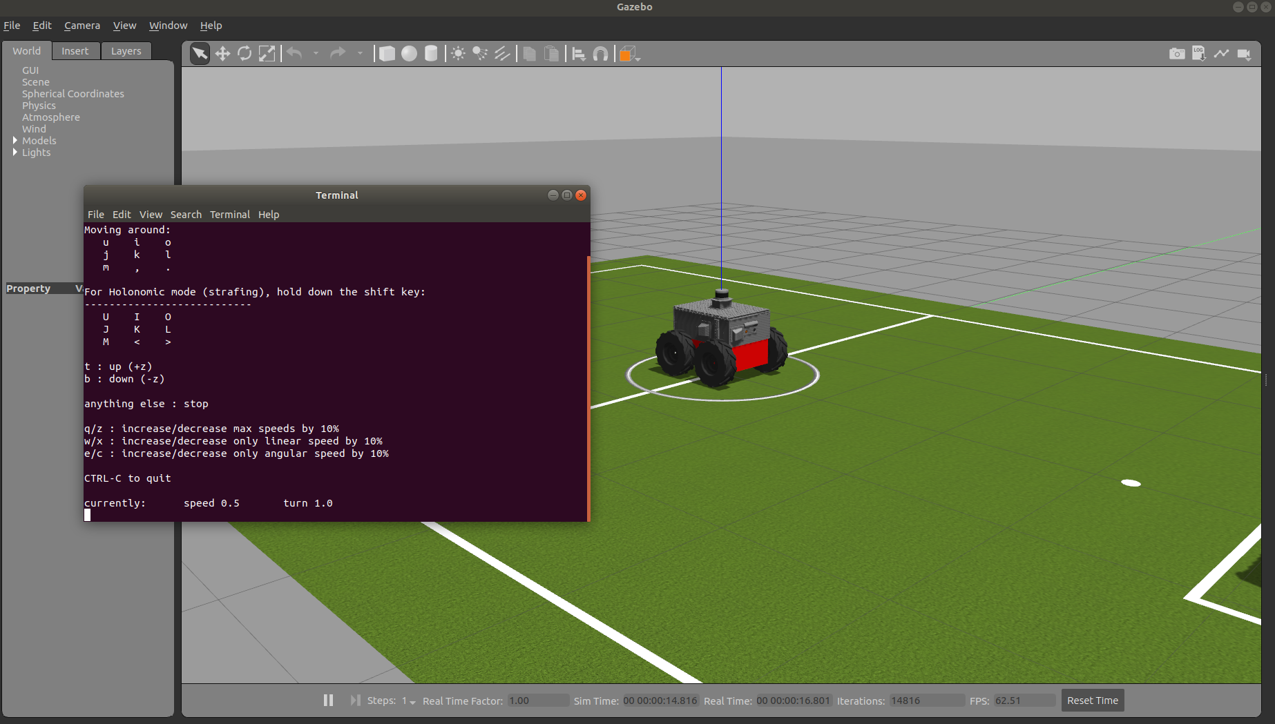
Run the launch file with the following command:
roslaunch smb_highlevel_controller smb_highlevel_controller.launch
 |
|---|
| Gazebo with SMB and teleop twist keyboard |
-
To control smb robot in gazebo through command line (press tab for autocompletion):
rostopic pub /cmd_vel geometry_msgs/Twist '[0.5,0,0]' '[0,0,0]'
-
The world file argument is hardcoded as follow:
<arg name="world_file" value="/usr/share/gazebo-9/worlds/robocup14_spl_field.world"/> -
To launch the teleop keyboard in a new terminal, set the
launch-prefixtoxterm -e
This exercise is based on lecture 2.
Run the launch file with the following command:
roslaunch smb_highlevel_controller smb_highlevel_controller.launch
The solution package template is based on ros_best_practices for python
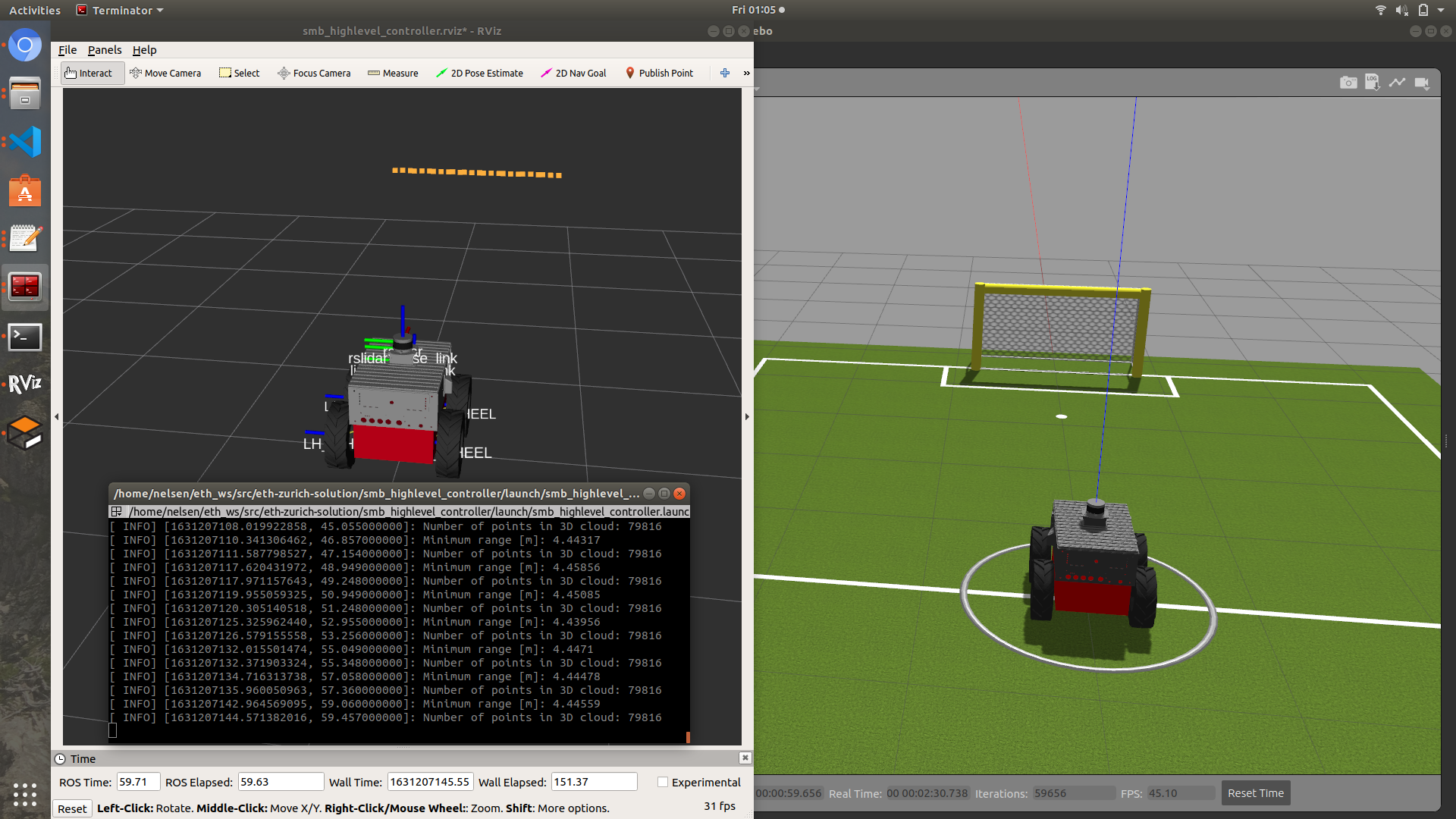
The solution output should be as follow:
 |
|---|
| Rviz with laserscan, terminal with output and gazebo |
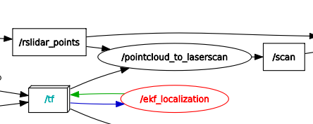
As can be seen from the rqt_graph, the pointcloud_to_laserscan node is subscribing to /rslidar_points which is a PointCloud2 message and /tf and converts it into a LaserScan topic /scan.
- consist of parameters that are passed to the launch file.
- Initialize the
smb_highlevel_controllernode
- Implementation of the class method including fetch parameters from launch
- Subscribe to topics name based on parameters server
- Implementation of callback method such as
scanCallbackandpclCallback.
- contains rviz file format which were created by running rviz seperately, adding the required display, and saving it into the rviz file.
- Add
<rosparam>to load default_parameters.yaml to parameter server. - Add
nodeto launch the smb_highlevel_controller.py script.
- Add
find_packageandcatkin_packageto find libraries such asrospyandsensor_msgs. - Install python executable based on the project name with
catkin_install_python.
- Add
dependfor the dependencies which arerospy,sensor_msgsandsmb_gazebo
Note: Change smb_common package to smb_common_v2 package
This exercise is based on lecture 3.
Run the launch file with the smb_highlevel_controller with the following command:
roslaunch smb_highlevel_controller smb_highlevel_controller.launch
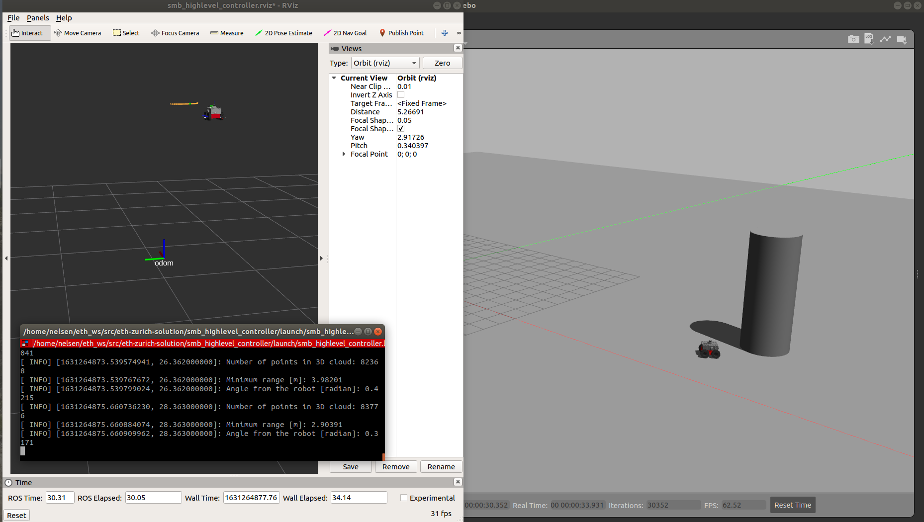
The solution output should be as follow:
 |
|---|
| Rviz with marker visualization indicate with the green color ball and tf marker, terminal with printed output such as the angle , and smb is heading towards the pillar in gazebo |
- Add dependencies such as
geometry_msgs,tf2_ros, andvisualization_msgspackage.
- Import
geometry_msgs,tf2_ros, andvisualization_msgspackage. - Add two publisher for topics
visualization_markerandcmd_velduring initialization. - Create a
goal_poseof typegeometry_msgs::PoseStampedwhich is the pillar from the lidar reading with respect to therslidarframe. - Create TF listerner and TF buffer to transform the
goal_posefrom therslidarframe toodomontransform_odom. - Utilize a P controller from the error angle to drive the error to zero on
move_to_goal, the x velocity is set to constant without P controller to ensure that the SMB hits the pillar. - Publish a visualization marker on
vis_marker_publishthat can be displayed in Rviz.
- Change the world argument value to
"$(find smb_highlevel_controller)/world/singlePillar.world" - Add two arguments under
laser_scan_min_heightandlaser_scan_max_heightto -0.2 and 1.0 respectively. - Remove the
teleop_twist_keyboardnode from the launch.
- Add
Markerdisplay to visualize the pillar marker indicated with green color ball.
This exercise is based on lecture 3 and lecture 4.
This exercise requires the use of rqt_multiplot. Run the following command to install rqt_multiplot:
sudo apt install -y ros-<distro>-rqt-multiplot
where <distro> can be either melodic or noetic based on your computer ROS_DISTRO.
The simulation can be run with the following command:
roslaunch smb_highlevel_controller smb_highlevel_controller.launch
To understand the EKF Localization Node, open another terminal, then open it with rqt_graph.
The output is the following:
 |
|---|
| ekf_localization node in rqt_graph |
As can be seen from the graph, the ekf localization subscribes to /imu/data and /smb_velocity_controller/odom topics and publishes /odometry/filtered topic by applying extended kalman filter. In this case, the topic will be displayed in both rqt_multiplot and rviz.
The solution output should be as follow:
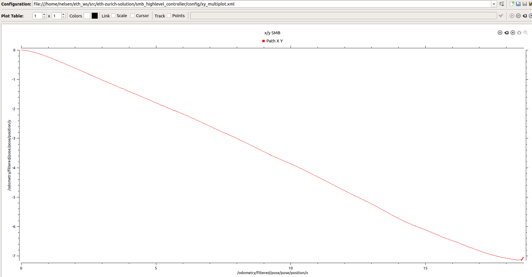 |
|---|
| Plot of x/y-plane that is taken by SMB (Kp = 30, x_vel = 3 m/s) until it hits the pillar on rqt_multiplot |
To get all the topics and messages inside the rosbag, run the following command:
rosbag info smb_navigation.bag
The solution should be as follow:

To run the recorded rosbag, use the following command:
roslaunch smb_highlevel_controller ekf_localization.launch
The solution output should be as follow:
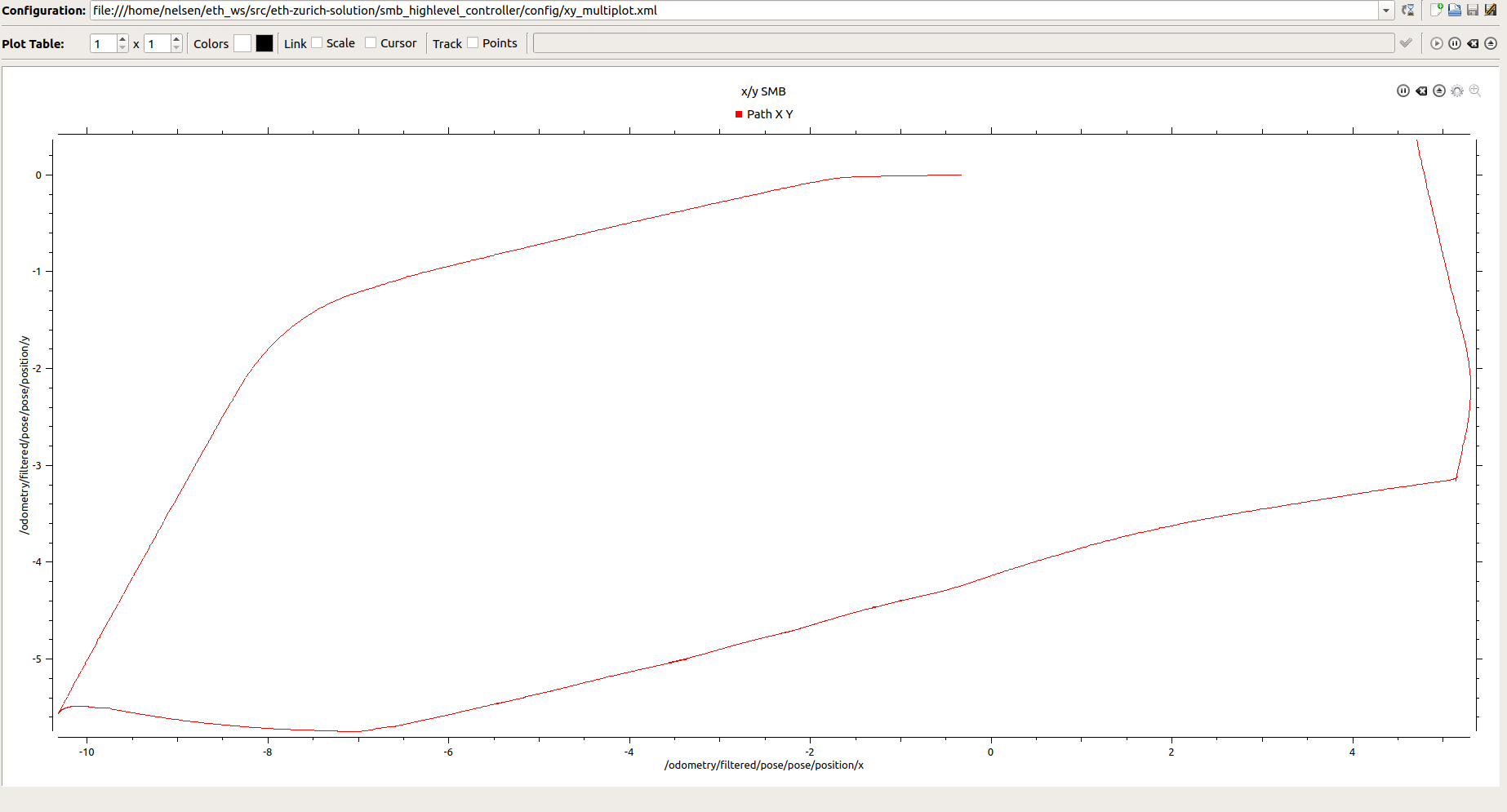 |
|---|
| Plot of x/y-plane plot that is taken by SMB until the rosbag recording ends |
The 3D point cloud as well as smb_top_view frame can be visualize in rviz:
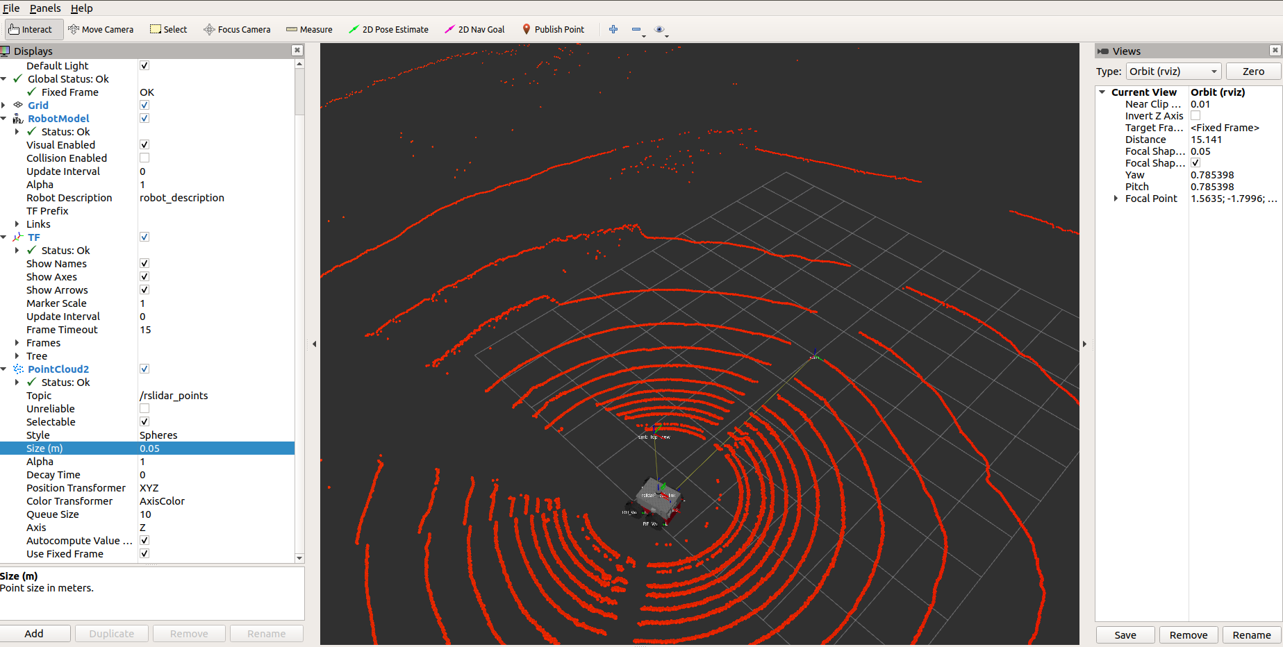 |
|---|
| 3D lidar point cloud and smb_top_view frame visualize in rviz |
The smb_top_view frame will move according to the base_link frame. As such, the smb_top_view is moving together with the robot in rviz when the rosbag is played.
- Contains 59.7 seconds of a recorded simulation.
- The size of the bag is 158.9 MB with total messages of 1545.
- The topics recorded are
/imu/data,join_states,rslidar_points, andsmb_velocity_controller/odom
- Create an x/y-plane plot of the smb based on the output of the
ekf_localizationnode which is/odometry/filteredwith typenav_msgs/Odometry.
- Display TF, PointCloud2, and RobotModel of the smb
- Add rqt_multiplot node with xy_multiplot.xml to plot the path of smb in x/y plane.
- Refer from control.launch file that is located on the
smb_controlpackage. - Add
ekf_robot_localizationnode and load the required parameters from the localization.yaml - Add
smb_robot_state_publisherto publish state of the robot to tf2 that is visualize in rviz. - Create a frame called
smb_top_viewwithstatic_transform_publishernode which is 2 meters above thebase_linkframe. - Add
rosbagnode to play rosbag with full speed or half speed. - Launch rviz with ekf_localization.rviz configuration.
- Add rqt_multiplot node with xy_multiplot.xml to plot the path of smb in x/y plane.
This exercise is based on lecture 4.
The service name /startService is defined inside default_parameters.yaml.
Run the launch file with the following command:
roslaunch smb_highlevel_controller smb_highlevel_controller.launch
To start the robot, run the following command on another terminal:
rosservice call /startService "data: true"
Alternatively you can run the robot during the startup with the following command:
roslaunch smb_highlevel_controller smb_highlevel_controller.launch start_robot:="true"
To stop the robot manually from colliding, open another terminal and run the following command:
rosservice call /startService "data: false"
The robot can always continue its path by calling the service by setting the data to true.
Run the launch file with the following command:
roslaunch smb_highlevel_controller smb_highlevel_controller.launch start_robot:="true" auto_emergency:="true"
By default, the robot will stop before hitting the pillar with a distance of max_distance_to_pillar from the robot's lidar that is specified in the default_parameters.yaml.
The solution output should be as follow:
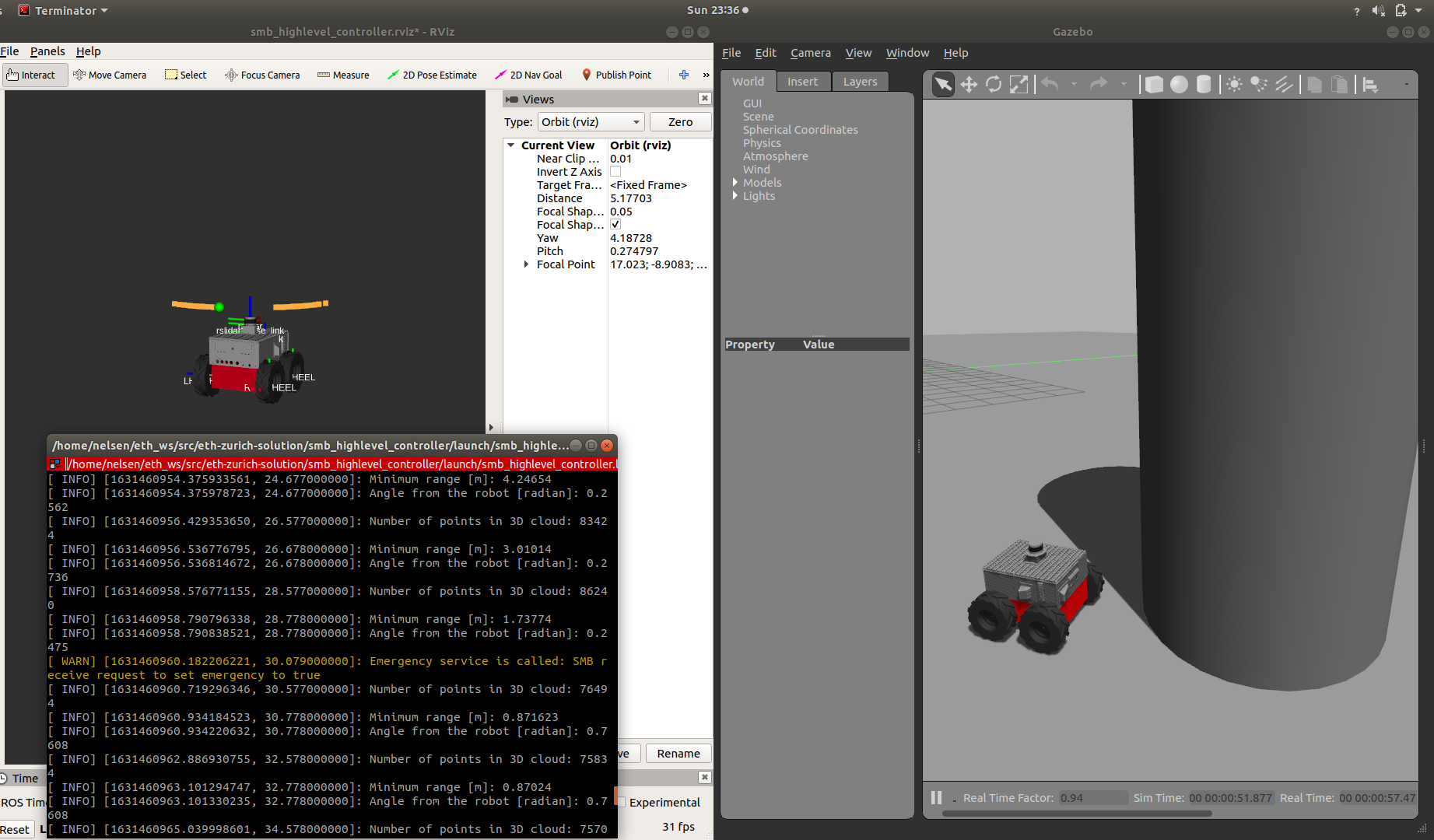 |
|---|
| The SMB stops before hitting the pillar. In the terminal, the service was called to stop the robot. |
Run the launch file with the following command:
roslaunch smb_highlevel_controller smb_highlevel_controller.launch start_robot:="true" auto_emergency:="true" prior_collision:="false"
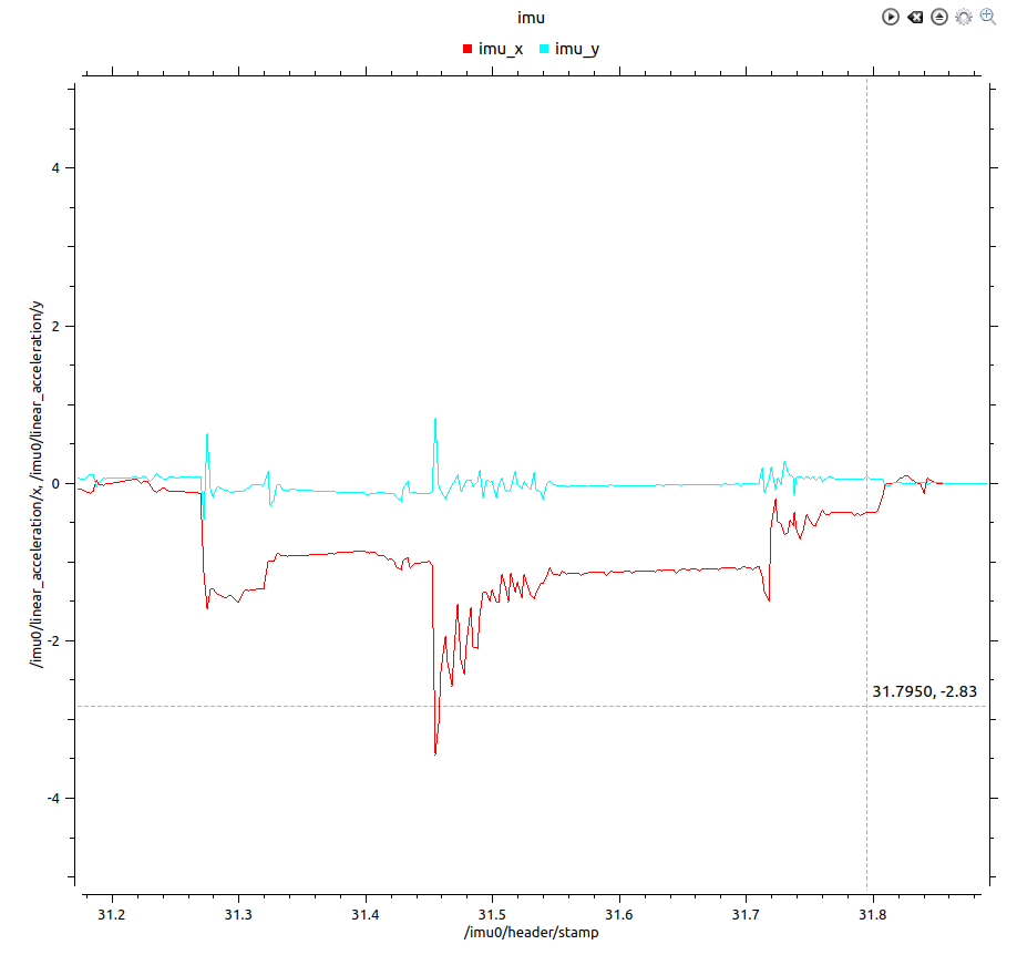
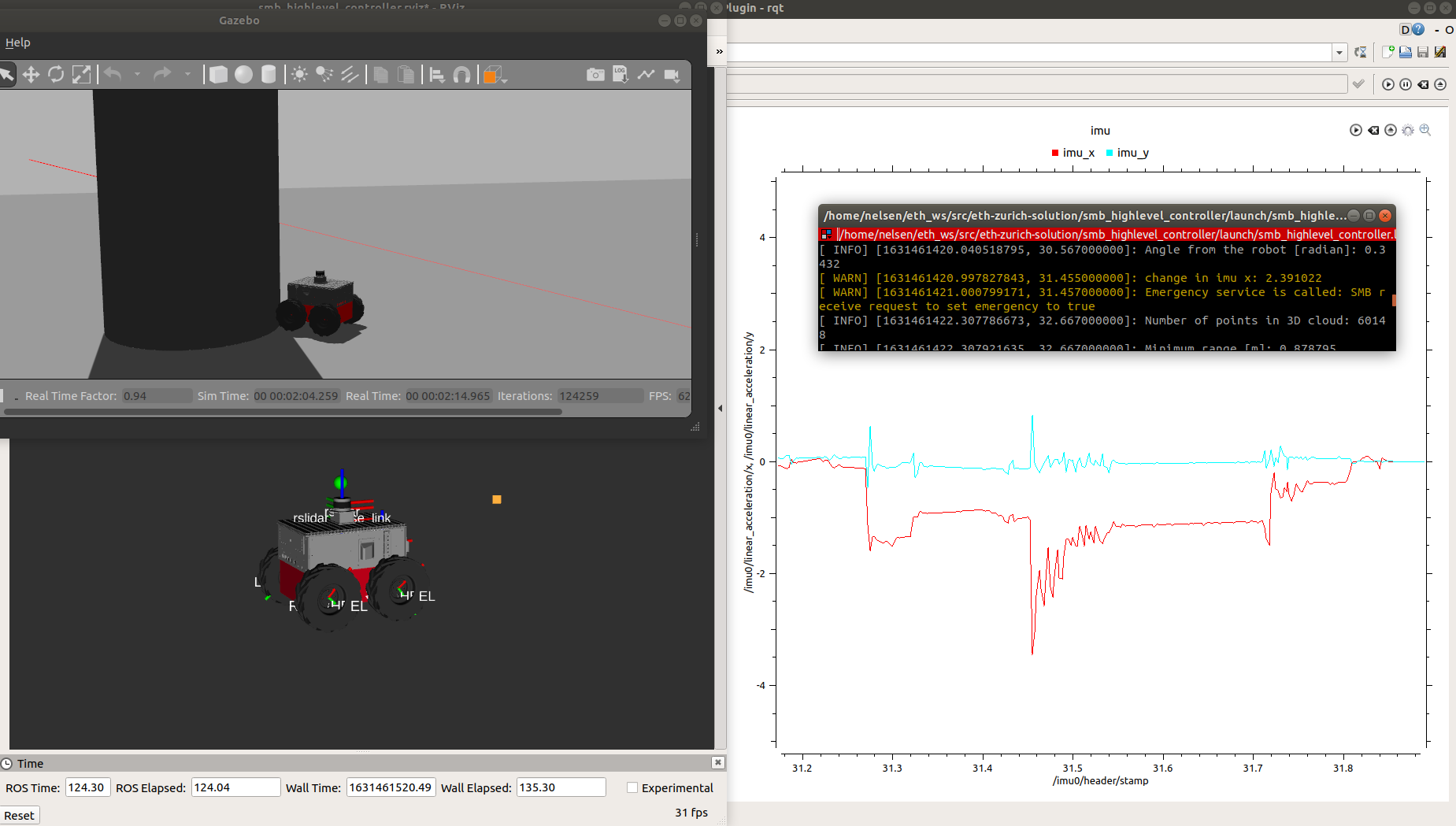
By default, the robot will stop after hitting the pillar based on collision_threshold which is the maximum change of IMU on x axis before the service is called that is specified in the default_parameters.yaml.
To get a proper collision_threshold, rqt_multiplot is launched with the xy_imu_multiplot.xml config.
During the collision, the x-axis IMU plot can be seen as follow:
 |
|---|
| The plot of IMU x-axis and y-axis plot during collision, there is a sudden spike of IMU x-axis with the value change of around 1.8 |
The overall output should be as follow:
 |
|---|
| The SMB stops after hitting the pillar. In the terminal, the service was called to stop the robot. |
- Add parameters for the service (i.e. service name, start_robot).
- Add start/stop server, service name and service callback based on the service call with
SetBool. - Add bool
isStart_to move the robot only if it is enabled.
- As the client, call the service to stop SMB robot with
SetBoolbased on the parameterprior_collision. - The parameters that can be adjusted are
max_distance_to_pillarfor prior collision andcollision_thresholdfor post collision. - This node is called from the launch file if the parameter
auto_emergencyis enabled.
- Create an x/y-plane plot of the smb and the x and y IMU data over time.
- Use arguments to load some of the params instead of
rosparamfrom default_parameters.yaml. This allow arguments to be passed from command line. - Add
stop_condition_nodeto automatically stop the SMB prior/post collision if enabled. - Change rqt_multiplot config with xy_imu_multiplot.xml to plot the path of smb in x/y plane as well as x and y IMU data over time.
- Add std_srvs in
find_package - Install python executable for
stop_conditionnode withcatkin_install_python.
- Add depend
std_srvsto useSetBoolservice.
