ROS package for robust and fast on the fly 3d sensor xy-orientation adjustment using the ground floor plane. Bascially fits a plane to a given input and re-projects the angle error to adjust the sensor frame pose (position and orientation). The fitting is not done "exact" and is not super accurate (~0.2? to ~1.0 degree accuracy, depending on the number of iterations) and seems to work only for "small" angle differences (< ~12 degree?). Should work well and accurately enough for most real life mobile robotic systems though.
The calculations are done in the 2D image space for fast computation (< ~10% CPU usage, input: 640x480@30Hz with Intel Haswell (2014) i7-4790 @ 3.6Ghz).
Pre-calculate multipliers m_px and m_py for estimating the angles later:
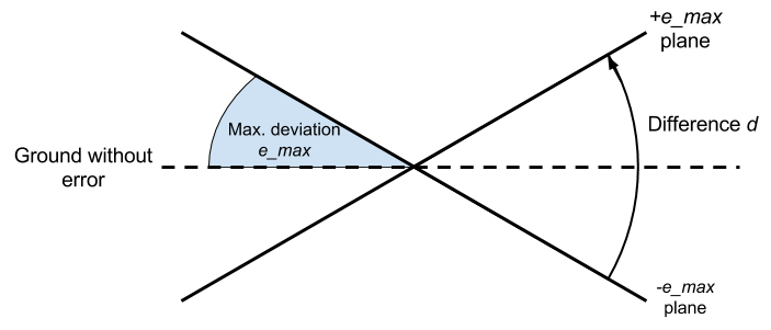
- Calculate planes which correspond to the maximum deviation
e_maxwe expect for the ground plane- Four planes: ±
e_maxaround x and y axis
- Four planes: ±
- Project planes back into sensor image space (aka "depth image") (= plane images)
- Calculate the sum of differences
d_px,d_pybetween ± x and ± y plane images - Calculate the multipliers with
m_px = e_max / d_px,m_py = e_max / d_py
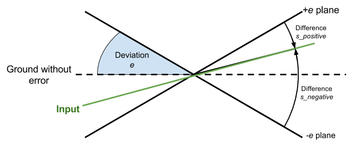
Estimate the angles:
- Start with
e = e_max - Calculate the plane images as in the pre-calculation above for
e - Calculate the four sums of differences
s_positive_px,s_negative_px,s_positive_py,s_negative_pybetween input data and the ±ex/y image planes - Calculate the differences of the sums of differences:
ds_px = s_negative_px - s_positive_pxds_py = s_negative_py - s_positive_py
- Multiply
ds_pxandds_pywith the pre-computed multipliersm_pxandm_pyto get the estimated angle offsetsoffset_pxandoffset_py - Use the
offsets + some_bufferas estimated deviationeand repeat from 2.ntimes - Sum up the offsets to get the plane xy orientation offsets
- Calculate camera transformation to negate the calculated ground plane angle offsets
Lazy / conservative update scheme:
- Always check if input has"enough" data "at the right place" to fit a plane
- If not then do nothing and keep broadcasting old transformation
- Calculate transformation once and keep using it if still fits the data
- The trigger is a certain amount of data points being below the ground level
- This works well if the robot moves only in a plane
- Warning: Causes problems with inclines / ramps and bigger sensor tilting (e.g. because of moving over obstacles)
- The trigger is a certain amount of data points being below the ground level
- If transformation does not fit the data, calculate new
- If new transformation fits the data, replace old transformation
- Else if new transformation does not fit, keep old
- Run the calibration only as fast as
calibration_rate, but publish the old transform every time we get input data
The scheme is using some ideas of the Iterative Closest Point-algorithm (ICP). Using the error between a guess and the input, a transformation can be calculated to iteratevly adjust the guess to fit the input. So the error gives an evaluation function how close the input is to the guess.
Using two opposite extrem guesses gives two errors. I run some simulation tests they showed that the true error is almost linear to ratio between the errors. This probably has some mathematical / geometrical reason which I didn't look into (feel free to write a paper on that). The residual error given a perfect ground plane could actually be easily estimated by a function fit, but the input data has some noise anyways and the iterative fitting works well enough. Maybe will do that in the future to converge with less iterations.
It should be mentioned that the multipliers depend on the distance of the fitted plane to the sensor. So it needs to be re-calculated every time this changes (in case someone wants to use this approach for something else).
The package is a nodelet and has a standalone launcher which just starts a nodelet manager and the nodelet for easy testing. It is set up to work out of a box if you run a sensor with the default openni2 launcher. But basically you want to attach the nodelet to the nodelet manager of your sensor driver for fast data transport.
The nodelet launcher has args for the sensor topics and a path to a parameter file.
The package heavily uses dynamic reconfigure for changing parameters on the fly. If the parameters are not specified in the parameter file, the defaults from the config file cfg/ are used.
There is a lot of debug information (gets a bit spammy, but explains always why something fails) if the reconfigure debug flag is set.
Instead of the ground_frame (default: base_footprint), also a manual ground transformation (from the reconfigure) can be used by checking the use_manual_ground_transform. The translation of the transformation has to be kind of accurate, same goes for the Z orientation. If debug is enabled a TF transform will be showing the pose.
If debug is enabled a lot of topics and some transforms are getting published with information of the intermediate steps of the calibration (input filtering, initial starting plane, ground plane estimation). Also variables which are checked for thresholding and limits are published as topics and can be introspected with e.g. rqt_plot.
Play around with the iterations parameter if the plane does not fit well enough. It can use a lot of CPU though and the default number of iterations (3) works reasonably well if the initial position is okish.