ROS wrapper for OpenPose ( https://github.com/CMU-Perceptual-Computing-Lab/openpose ) allows the estimation of 2d multi-person pose from a single RGB camera (see commit number a1e0a5f4136e702b5731a268c2993fb75ca4753c ). Based on https://github.com/stevenjj/openpose_ros .
When a depth image is synchronized with the RGB image (RGB-D image), a 3d extractor node has been implemented to obtain 3d pose estimation from the 2d pose estimation given by OpenPose through the projection of the 2d pose estimation onto the point-cloud of the depth image. Also, a visualization node for the 3d results has been implemented.
- Install openpose and its dependencies ( https://github.com/CMU-Perceptual-Computing-Lab/openpose/blob/master/doc/installation.md)
NOTE: OpenCV 3.2 recommended, as OpenCv 2.4 might cause some errors.
-
Install PCL (http://pointclouds.org/downloads/)
-
Enable the package running in openpose_ros directory:
./install_openpose_and_enable_package.sh
- If it succeds, compile:
cd ~/catkin_ws/src
catkin build
cd ..
source devel/setup.bash
The package can be divided into two modules that work independently. One for 2d pose detections, with a visualization tool like the one in OpenPose but implemented in ROS. And another for 3d pose detections, with a visualization node to view the results with RViz. We use the same node to get OpenPose 2d detections for both modules, but we have duplicated it and the services it provides with different names to avoid trouble while calling it with the 2d visualization tool and the 3d extractor node simultaneously.
This module is composed of a service node for getting 2d detections and a node for the output visualization.
First of all, you might want to change some things in the code to adapt it to your necessities:
- Go to
/openpose_ros_pkg/src/openpose_ros_node_firephinx.cpp, and change/usb_cam/image_rawfor the topic your camera is publishing thesensor_msgs::Imagemessages to:

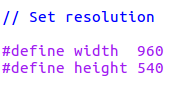
- You may change the output image resolution. To do so,
/openpose_ros_pkg/src/openpose_ros_node_firephinx.cppand change:

Once you have set those parameters repeat step 4 of installation.
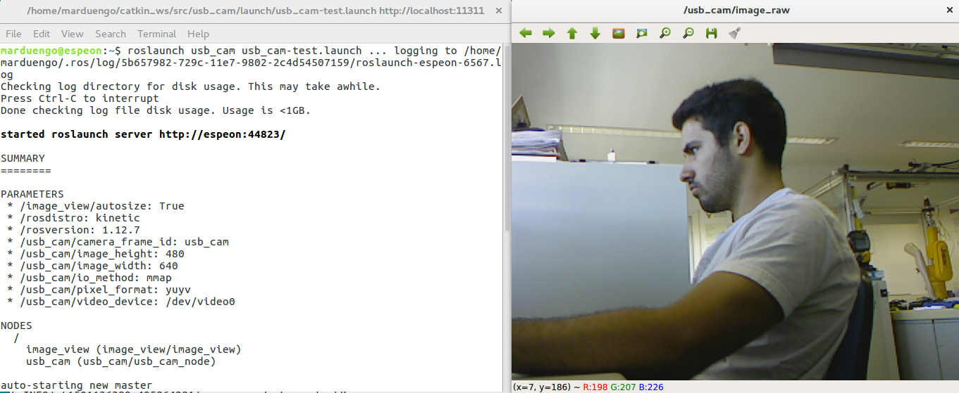
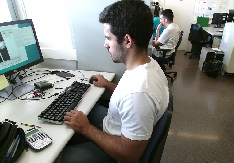
Now you can run the code. First connect a RGB camera and run the corresponding ROS drivers to start to publish the images (they must be image_raw). For example you can connect a webcam and use https://github.com/ros-drivers/usb_cam. With this drivers run:
roslaunch usb_cam usb_cam-test.launch
You should get the something like:
Then, initialize the 2d detection service node:
rosrun openpose_ros_pkg openpose_ros_node
If everything works fine you should see the following output in your shell:
[ INFO] [1501140533.950685432]: Initialization Successful!
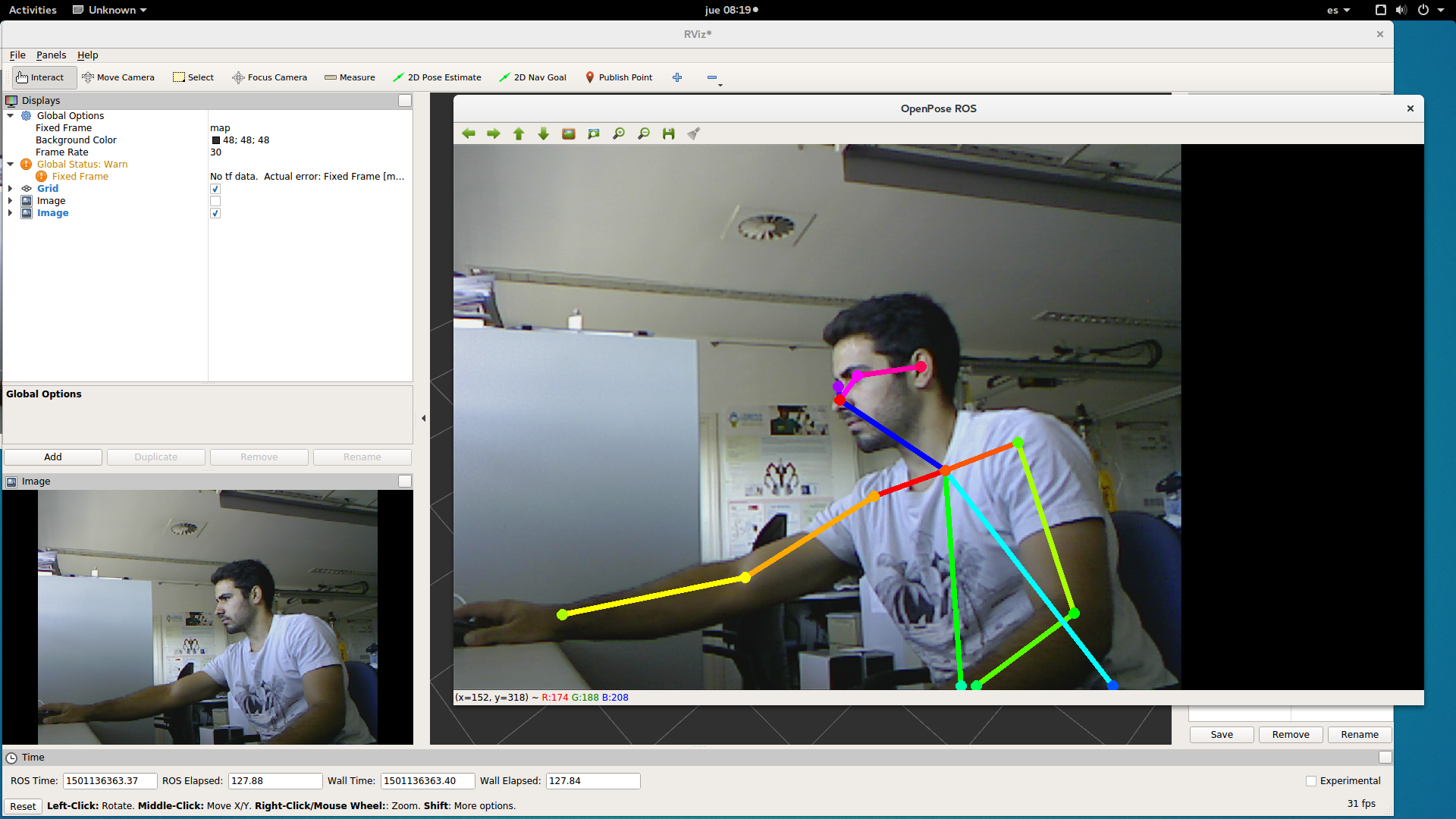
Finally, to get the 2d poses of the images from the camera and visualize the output, run:
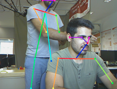
rosrun openpose_ros_pkg openpose_ros_node_firephinxYou should obtain something similar to:
If everything is running correctly, the package should be publishing in the topics:
/openpose_ros/input_image
/openpose_ros/detected_poses_image
/openpose_ros/detected_poses_keypoints
- /openpose_ros/input_image: The images the 2d detection node is taking to make the segmentation are published here.
- /openpose_ros/detected_poses_image: Images with the segmentation skeleton drawn in it are published here.
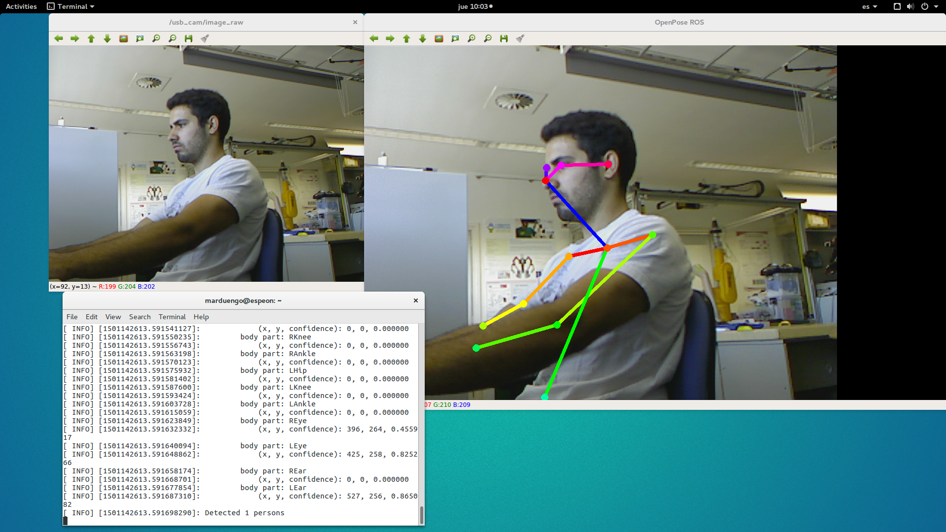
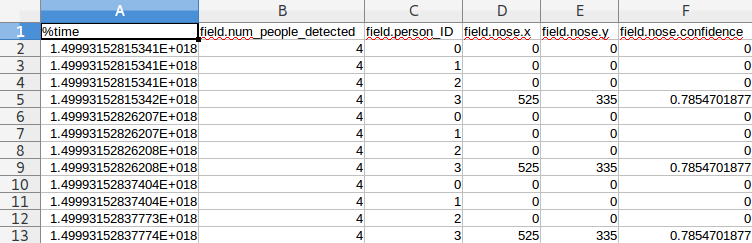
- /openpose_ros/detected_poses_keypoints: In this topic, the messages with the 2d detections keypoints (openpose bodyjoints) are being published. The messages have the following fields:
- num_people_detected: number of people that are in the image.
- person_ID: ID number assigned to each person.
- bodypart (i.e. nose): Each bodypart has the following fields:
- x: x openpose keypoint pixel coordinate.
- y: y openpose keypoint pixel coordinate.
- confidence: confidence of the detection.
If you write the data in a csv it should be like this:
This module is composed of the same 2d extractor node described in the previous section, a node for getting 3d pose detection and a node for visualization of the output in RViz. We can see the resulting 3d human skeleton and the resulting 3d detections for the joints or both at the same time with the visualization node. An RGB-D camera is needed to run this module.
First of all you might want to change some things in the code to adapt it to your necessities:
- Go to
/skeleton_extract_3d/launch/openpose_skeleton_extract.launch. You will see this:
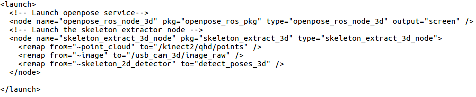
*Here you should change /usb_cam_3d/image_raw/ for the topic your camera will be publishing the sensor_msgs::Image messages (RGB images). You should also change /kinect2/qhd/points for the topic your camera will be publishing the sensor_msgs::Pointcloud2 messages (depth images).
- Go to
/skeleton_extract_3d/src/skeleton_extract_3d_node.cppand set the input resolution of the images (the resolution of the depth and the RGB images must be the same):
- Go to
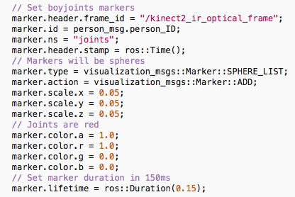
/skeleton_extract_3d/src/skeleton_extract_3d_visualization_node.cpp. You might want to change the color, shape, size etc. of the markers. To see the options you have go to http://wiki.ros.org/rviz/DisplayTypes/Marker. To set the options of the bodyjoints:
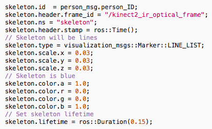
To set the options of the skeleton, go to:
Once you have set the options repeat step 4 of the installation process. Now that you have configured it, you can run the code. First of all connect your RGB-D and run the corresponding ROS drivers.
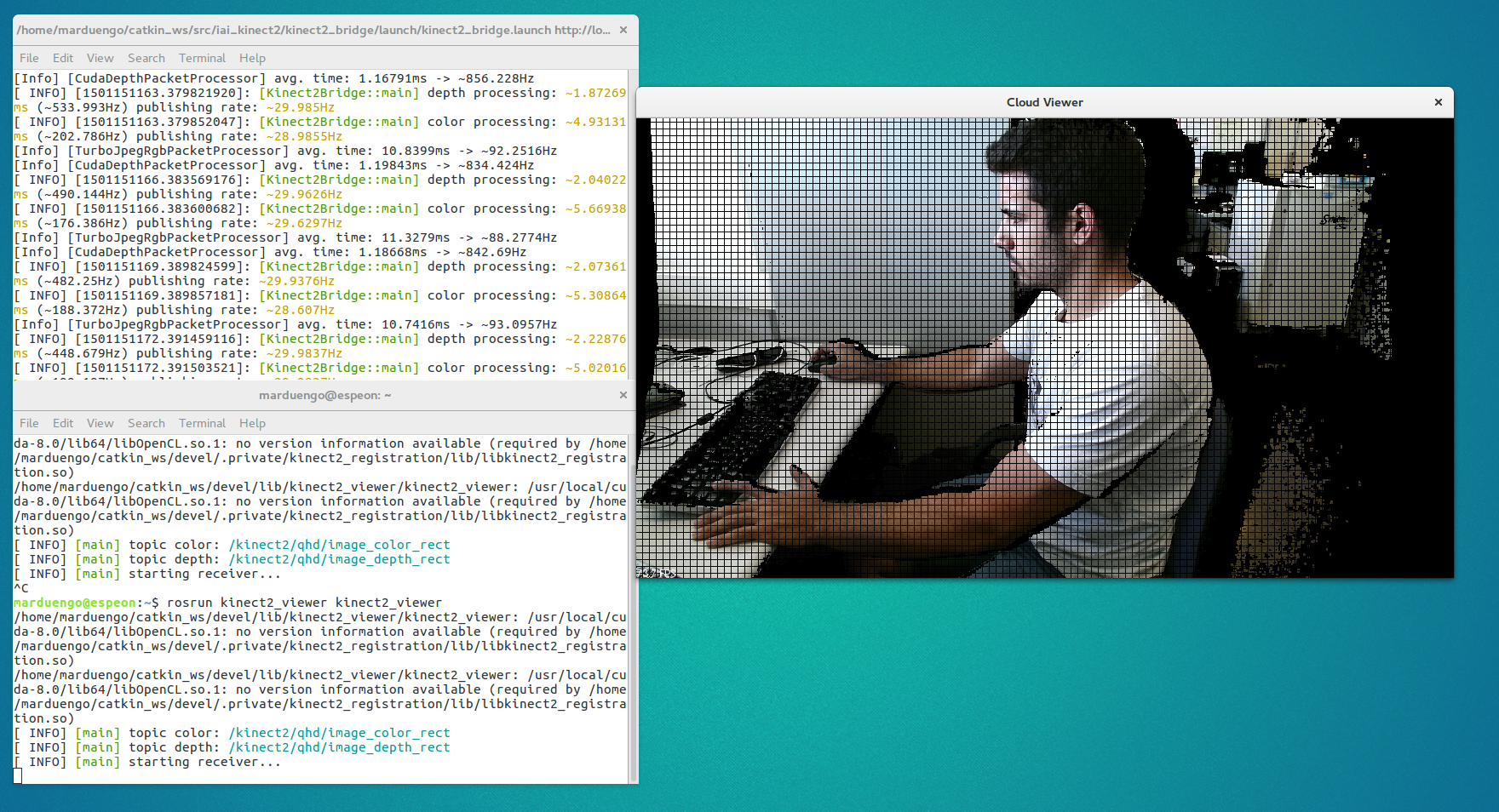
For example you can use a KinectOne and https://github.com/code-iai/iai_kinect2 ROS drivers. To initialize the camera with this drivers run:
roslaunch kinect2_bridge kinect2_bridge.launch
rosrun kinect2_viewer kinect2_viewer
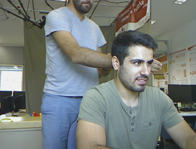
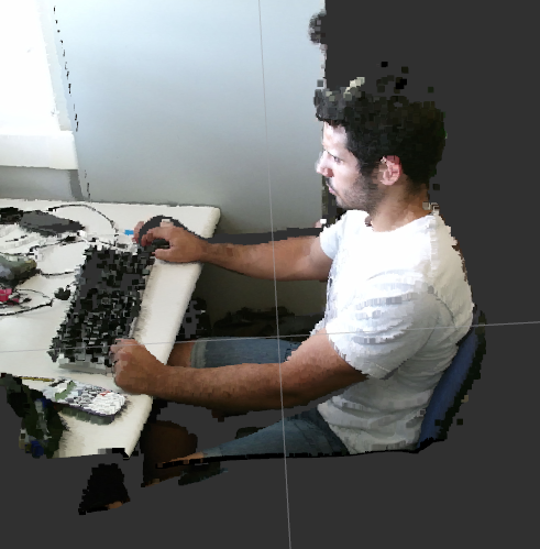
Then you will see the camera output:
Once your camera is publishing, launch the 2D extractor node and the 3D extractor node by running:
roslaunch roslaunch skeleton_extract_3d openpose_skeleton_extract.launch
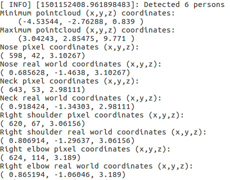
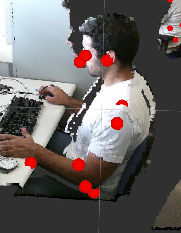
If everything is working fine you should have something similar to:
Then you can run the visualization node:
rosrun skeleton_extract_3d skeleton_extract_3d_visualization_node
NOTE: To have the fixed frame for visualization you must run:
rosrun kinect2_bridge kinect2_bridge _publish_tf:=true
Now open rviz and select as fixed frame the one you have set for the markers. For example, I have chosen:
kinect2_ir_optical_frame
Select the topics:
/openpose_ros/skeleton_3d/visualization_markers
/openpose_ros/skeleton_3d/visualization_skeleton
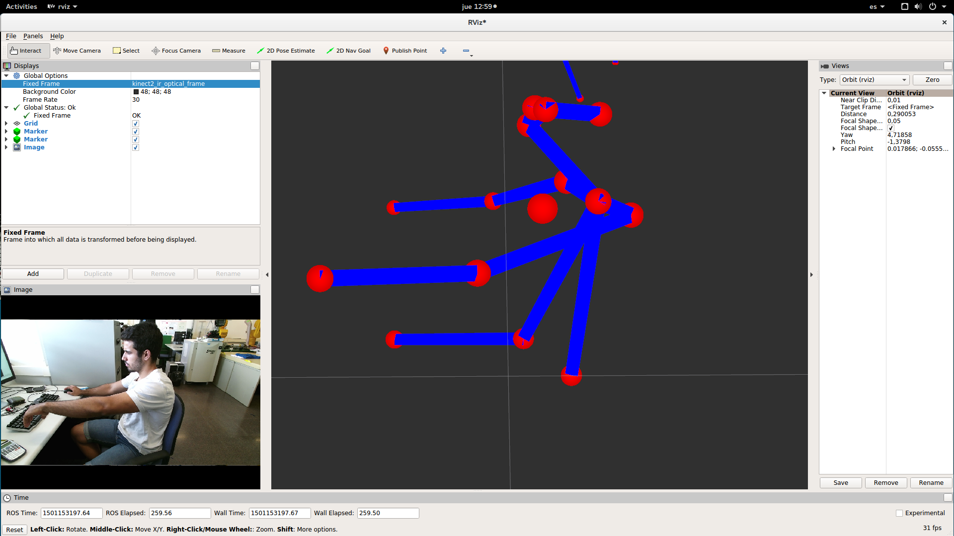
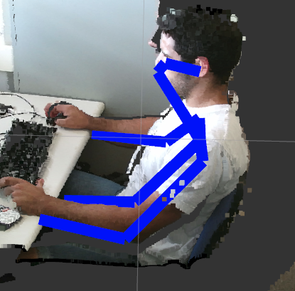
and you should have something similar to:
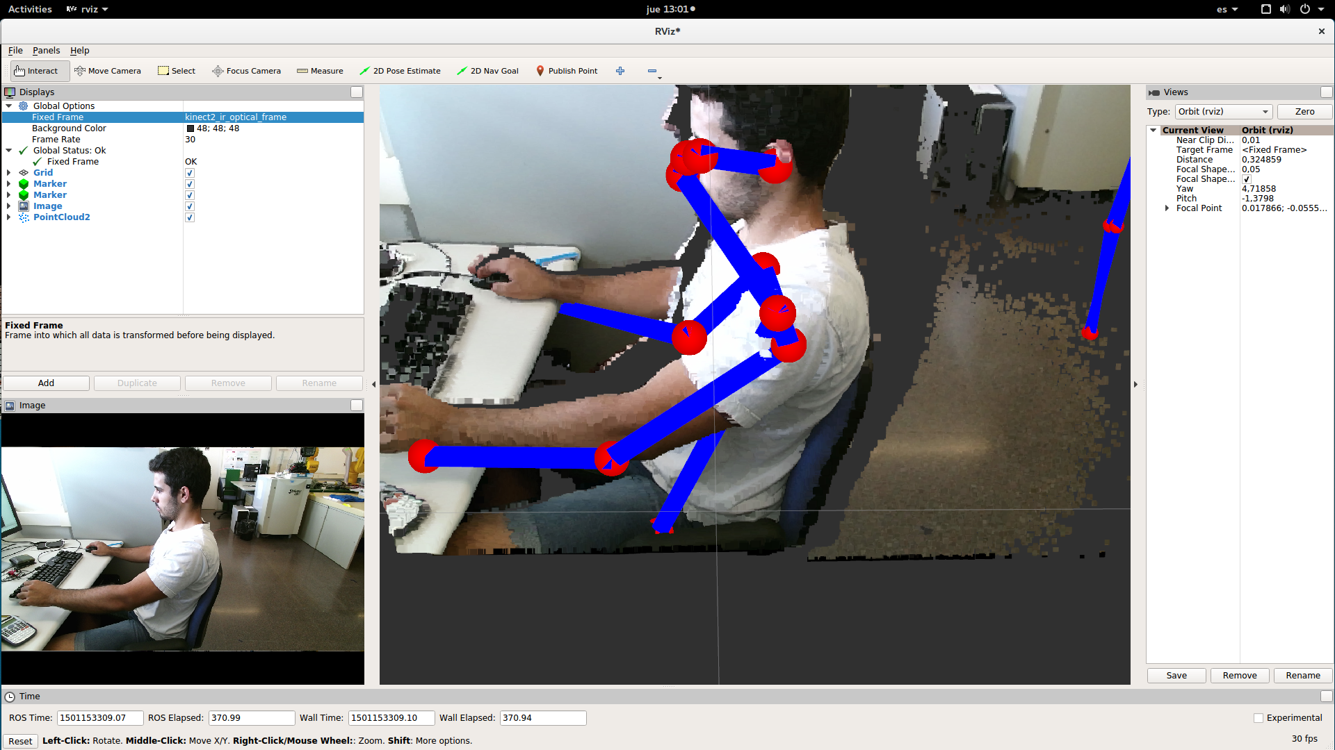
You can also select the pointcloud at the same time:
/openpose_ros/skeleton_3d/detected_poses_image
/openpose_ros/skeleton_3d/detected_poses_keypoints
/openpose_ros/skeleton_3d/detected_poses_keypoints_3d
/openpose_ros/skeleton_3d/input_pointcloud
/openpose_ros/skeleton_3d/input_rgb
/openpose_ros/skeleton_3d/visualization_markers
/openpose_ros/skeleton_3d/visualization_skeleton
-
/openpose_ros/skeleton_3d/detected_poses_image: the same kind of messages are published in this topic as in topic
/openpose_ros/detected_poses_imagein the 2d module. -
/openpose_ros/skeleton_3d/detected_poses_keypoints: the same kind of messages are published in this topic as in topic
/openpose_ros/detected_poses_keypointsin the 2d module. -
/openpose_ros/skeleton_3d/detected_poses_keypoints_3d: the 3d detections are published in this topic. The fields are the same as the mesagges published in
/openpose_ros/skeleton_3d/detected_poses_keypointsbut the fields of each bodypart change. Now they are:- x: x real world coordinate of the joint.
- y: y real world coordinate of the joint.
- z: depth real world coordinate of the joint.
- confidence: confidence of the 2d detections.
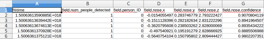
If you write the message in a .csv, it should look like this:
- /openpose_ros/skeleton_3d/input_pointcloud: Here is published the point-cloud that is synchronized with the RGB image from where we extract the x,y, z real world coordinates of the keypoints.
- /openpose_ros/skeleton_3d/input_rgb: the RGB image that we use to make the 2d detections is published in this topic and it is synchronized with the input point-cloud.
- /openpose_ros/skeleton_3d/visualization_markers: the markers to visualize in RViz the 3d detections of the joints are published in this topic.
- /openpose_ros/skeleton_3d/visualization_skeleton: the skeleton to visualize in RViz the 3d detections is published in this topic.
Miguel Arduengo García
Undergraduate student at CFIS-UPC (Barcelona Tech, Spain).
CFIS-UPC: https://cfis.upc.edu/es
Barcelona Tech: http://www.upc.edu/?set_language=en
Please cite the tech report if it helps in your publications:
Arduengo, M., Jorgensen, S.J., Hambuchen, K., Sentis, L., Moreno-Noguer, F., Alenyà, G. "ROS wrapper for real-time multi-person pose estimation with a single camera". Technical Report IRI-TR-17-02, Institut de Robòtica i Informàtica Industrial, CSIC-UPC, 2017.