Write structural Verilog code for a synchronous modulo-12 counter using D flip-flops. Implement an OOP-based test bench to test the counter’s functionality. Treat the DUT as a black box and compare the output against the expected results. Inputs: Clock, Reset. Expected Output: 0000, 0001, 0010, 0011, ..., 1010, 1011.
The synchronous modulo-12 counter is a vital digital circuit widely used in various applications including frequency dividers, frequency synthesizers and event sequencers. Its purpose is to count in a cyclical pattern from 0000 to 1011.
This project presents a synchronous modulo-12 counter design using D flip-flops in System Verilog. An object-oriented test bench is used to verify the counter’s functionality, comparing its output against the expected sequence (0000 to 1011). The test bench employs synchronous clock and asynchronous reset signals to simulate the counter’s behavior, ensuring accurate modulo-12 counting. This implementation can be applied to various digital systems requiring modulo counting such as frequency dividers and timing generators.
Programming Language Used: System Verilog
Software Used: Vivado ML 2023.1, Icarus Verilog, VS Code, GTKWave.
Hardware Used: Spartan 3
The synchronous modulo-12 counter is a digital circuit that counts through a predefined sequence of states in a cyclic manner, following the modulo-12 sequence (0000 to 1011). It is designed using D flip-flops to achieve synchronous operation, ensuring precise state transitions with each clock pulse. The counter module has two main inputs: the clock signal (CLOCK) and the reset signal (RESET).
i. Initialization: At power-up or when the reset signal (RESET) is asserted, the counter is initialized to its initial state (0000). The reset signal ensures that the counter starts counting from the first state.
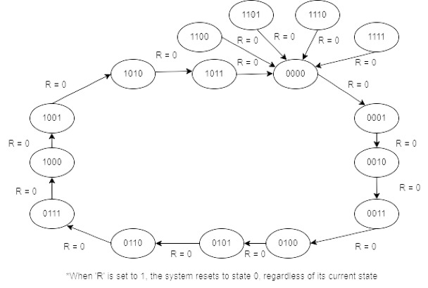
ii. State Transitions: When the reset signal is deasserted and the clock signal (CLOCK) starts oscillating, the counter begins its operation. With each rising edge of the clock signal, the counter’s state transitions.The counter counts in a binary sequence from 0000 to 1011 and wraps back to 0000, following the modulo-12 behavior. As the clock pulses, the counter increments through the binary states.
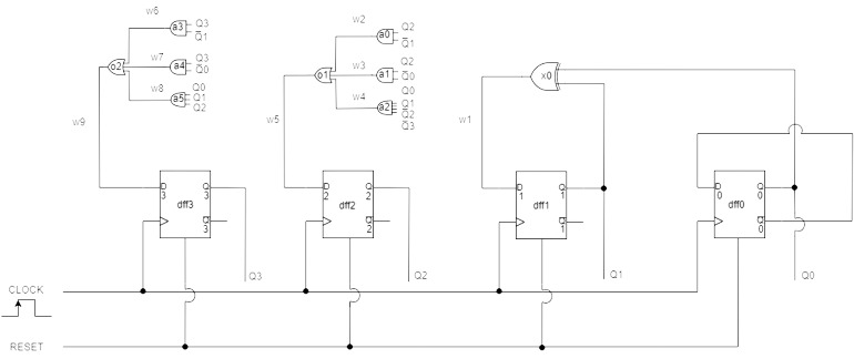
iii. Synchronous Operation: The use of D flip-flops ensures synchronous operation. On each rising edge of the clock signal, the data input (D) of each D flip-flop is updated with the value of its previous flip-flop’s output (q[n-1]), where ‘n’ is the current bit position of the counter. This synchronous behavior ensures that all flip-flops change their states simultaneously, avoiding any glitches or hazards that might occur in an asynchronous counter.
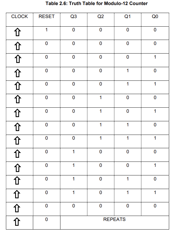
iv. Output: The counter’s output is represented by the four-bit binary values (q[3:0]). These outputs correspond to the current state of the counter and provide the binary representation of the modulo-12 count. The counter cycles through the states 0000, 0001, 0010, 0011, ..., 1010, 1011, and then wraps back to 0000, forming a continuous cyclic counting sequence.
v. Verification: To ensure the correctness of the counter’s behavior, an OOP-based test bench is utilized. The test bench generates input stimuli, including clock pulses and reset signals, to simulate various scenarios and exercise different counter states. During simulation, the test bench monitors the counter’s outputs and compares them against the expected output sequence (0000 to 1011). Any inconsistencies between the simulated output and the expected output are logged and analyzed to verify the counter’s functionality.
i. d_flip_flop.sv: The ‘d_flip_flop’ module implements a D flip-flop using a behavioral approach. It takes a data input ‘d’, a clock signal ‘clk’, and a reset signal ‘reset’. On the rising edge of the clock, the D flip-flop stores the input value ‘d’ in its output ‘q’. The complementary output ‘qb’ is the inverse of ‘q’. If the reset signal is asserted, ‘q’ is set to 0 and ‘qb’ is set to 1. Otherwise, ‘q’ takes the value of the input ‘d’ and ‘qb’ takes the value which is complement to ‘q’.
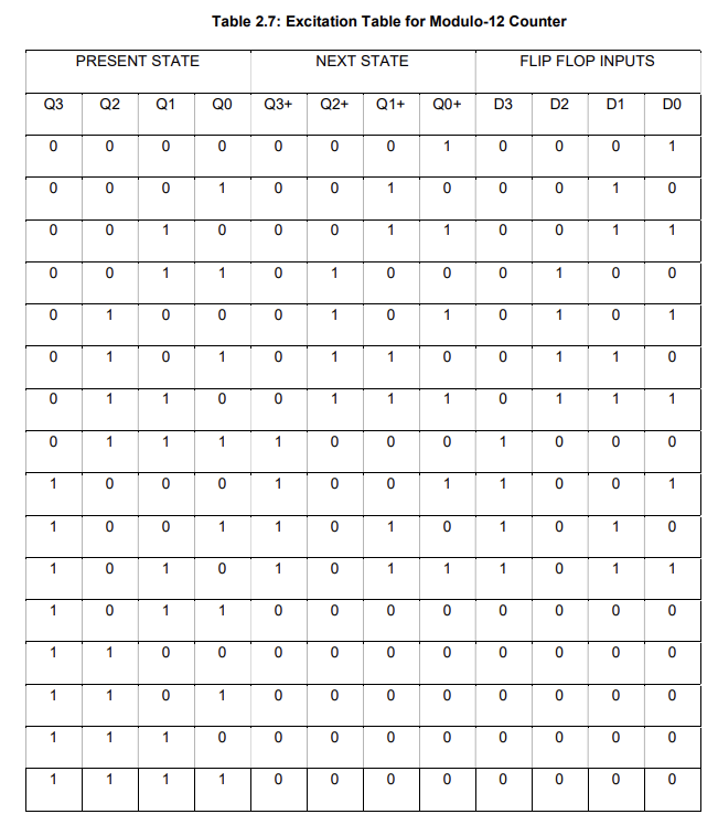
ii. modulo12counter.sv: The ‘modulo12counter’ module implements a synchronous modulo-12 counter using D flip-flops in a structural approach. It has a 4-bit output ‘q’ representing the counter’s current count in binary form. The counter counts from 0 to 11 (0000 to 1011) and then rolls over back to 0 (0000) to repeat the pattern. The counter uses four D flip-flops (‘d_flip_flop’) to store the binary count. It also employs combinational logic gates (‘and’, ‘or’, ‘xor’) to generate the next states of the counter.
iii. modulo12counter_tb.sv: The ‘modulo12counter_tb’ module implements a test bench for the modulo-12 counter. The ‘clk’ and ‘reset’ signals are declared as ‘reg’, and the counter output ‘q’ is declared as ‘wire’. The test bench generates the clock signal with a 50% duty cycle. Initially, the reset signal is asserted to reset the counter. After a short delay, the reset signal is deasserted and the counter starts counting. The test bench simulates the counter for 30 clock cycles and then terminates the simulation. It displays the counter output (‘q’) at every positive edge of the clock.
iv. counter_pkg.sv: The ‘counter_pkg’ package defines the ‘Mod12Counter’ class, describing the counter’s behavior using OOP concepts. It has member variables ‘q’, ‘clk’ and ‘reset’ with the constructor initializing them. The class includes two functions: ‘update’ to implement modulo-12 logic, incrementing the counter unless reset is asserted and resetting it to 0 when reaching 11 and ‘getOutput’ to read the current counter value (‘q’).
v. countertb.sv: The ‘countertb’ module is an OOP-based test bench for the modulo-12 counter. It imports ‘counter_pkg’, instantiates ‘modulo12counter’ (‘dut’) with ‘clk’, ‘reset’ and ‘q’ signals. ‘mod12counter_expected’ tracks the expected output. The test bench initializes ‘clk’ with 50% duty, asserts ‘reset’ initially, then deasserts it after a short delay. The 'verify' task compares 'q' with expected output from the ‘Mod12Counter’ class. The results are displayed at each positive clock edge to ensure the counter's correctness.
FPGA codes:
vi. mod12counter.v: This Verilog code defines a synchronous modulo-12 counter implemented using D flip-flops. The main module, mod12counter, takes a clock (clk) and a reset signal (reset) as inputs and outputs the counter value (q), display segments (segment), and a control signal (ctrl). The code uses divided clock signals (clkdiv and clkdiv2) to control different sections of the circuit. The counter logic, triggered by the positive edge of clkdiv2, updates the counter value and corresponding display segments based on a case statement. The circuit includes D flip-flops and logic gates to implement the modulo-12 behavior. The reset signal resets the counter, and the clock signal (clk) governs the overall operation. In essence, this code creates a modulo-12 counter with display functionality, suitable for FPGA implementation.
vii. mod12counter.ucf:
-
The 8 bits of the "segment" output are assigned to specific pins on your FPGA. For example, "segment[7]" is assigned to pin P1, "segment[6]" to P12, and so on.
-
The 4 bits of the "ctrl" output are also assigned to specific pins. "ctrl[3]" is assigned to pin P30, "ctrl[2]" to P29, "ctrl[1]" to P27, and "ctrl[0]" to P26.
-
The clock signal "clk" is assigned to pin P55.
-
The reset signal "reset" is assigned to pin P80.
Run this command in terminal window of VS Code / Windows Terminal to compile the files:
iverilog -g2005-sv -o op.vvp d_flip_flop.sv modulo12counter.sv counter_pkg.sv countertb.sv
After successful compilation run this command to get the output:
vvp op.vvp
Run this command to observe waveforms in GTKWave software:
gtkwave countertb.vcd
Output in Terminal Window of VS Code using Icarus Software:
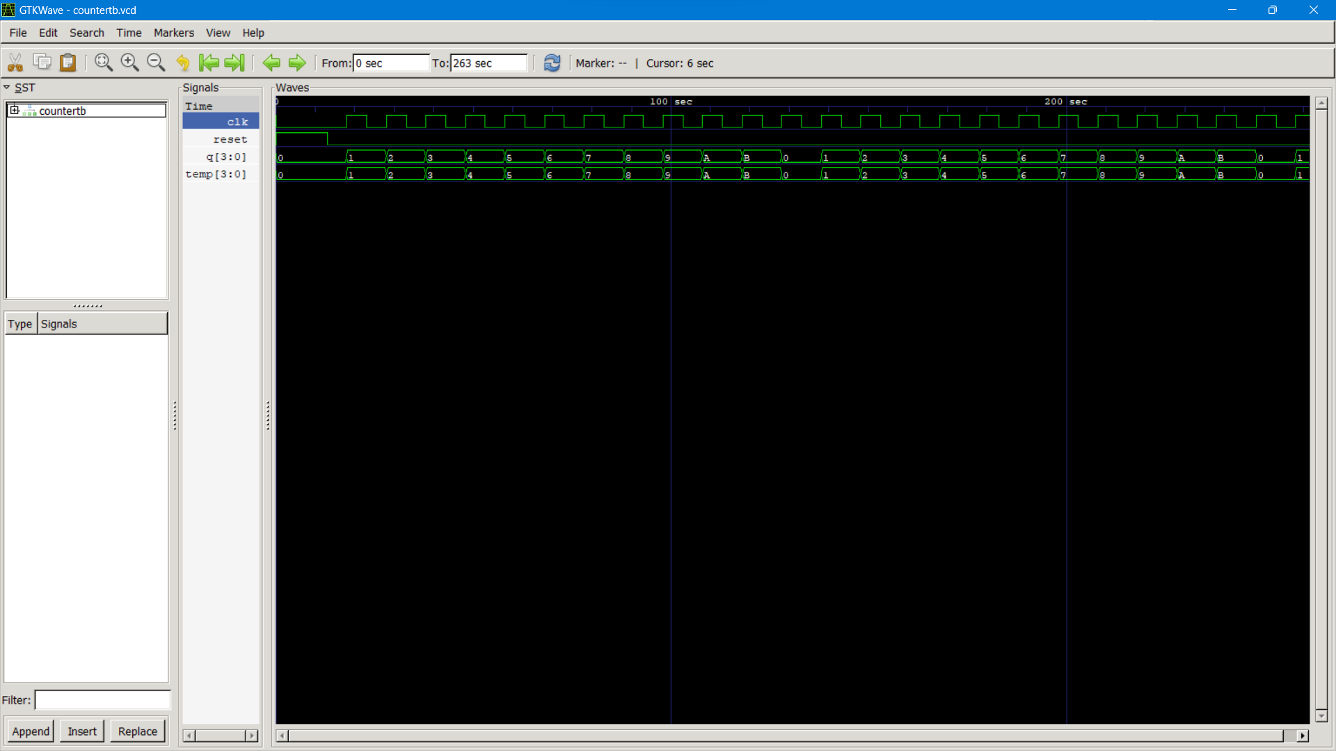
Output Waveform using GTKWave:
Implementation of Code on FPGA Device:
fpga_impl_sv.mp4
Code Used from mod12counter_onFPGA folder : d_flip_flop.v, mod12counter.v file, mod12counter.ucf (this is generated from Plan Ahead tool)
The Verilog code for synchronous modulo-12 counter using D flip-flops was successfully implemented and tested, counting accurately from 0000 to 1011 without glitches. While software simulation verified its correctness, real-world testing is essential. During testing, various errors were encountered, including logical errors, LSB and MSB mismatches and reversed outputs. Interestingly, the Icarus Verilog simulator initially produced different result compared to expected output, while Vivado software provided the expected result. Adding a display function after reset in line 17 of countertb.sv file resolved the issue, providing a perfect output as shown . The output waveform generated during testing was used to verify the expected and required output and the comparison is represented . The expected output and the actual output matched perfectly as per the truth table.
The synchronous modulo-12 counter using D flip-flops was successfully implemented, accurately counting from 0000 to 1011. While software testing provided positive results, real-world testing is necessary for practical applications. Synchronous counters are crucial for accurate counting in complex systems. They find practical uses in digital communication, industrial control, time measurement, signal processing, embedded systems, and test equipment. Real-world testing is vital for practical application validation. For future development, exploring hardware implementation can further validate its practical usefulness.
[1] Website: Design a mod-12 synchronous up counter, Computer Engineering. ExpertsMind.https://www.expertsmind.com/questions/design-a-mod-12- synchronous-up-counter-30160762.aspx. Referred on 23-07-2023.
[2] Website: SystemVerilog Tutorials. SystemVerilog Functions. Chip Verify. https://www.chipverify.com/systemverilog/systemverilog-tutorial. Referred on 25-07-2023.
[3] Website: Manishkj116. Counter Design using verilog HDL. GeeksForGeeks.https://www.geeksforgeeks.org/counter-design-using-verilog-hdl/. Referred on 25-07-2023.
[4] YouTube Video: Techno Tutorials (e-Learning). October 6, 2021. MOD 12 Synchronous Up Counter Using D Flip Flop | MOD 12 Counter | Digital electronics. https://youtu.be/ZBIl31r4lYM. Referred on 23-07-2023.
[5] YouTube Video: ElectroTech CC. October 19, 2020. 4-bit Mod-12 Synchronous Counter using D flip-flop || Sequential Logic Circuit | Digital Electronics. https://youtu.be/0jxvgMORUCE. Referred on 27-07-2023
