This goal of this Digital I/O library is to ease the use of simple sensors and devices attached to Digital I/O pins.
If you like this library please star or comment on github to pat me in the back and let others know it exists

- It can debounce noisy signals to avoid program glitches
- It has level and spike detection to support things like button presses or transient knock sensor signals.
- It is nimble and compact. Classes use the minimum amount of RAM to hold data (usually 1 byte), and classes rely on constant folding to optimize codewithout sacrificing functionality. Methods often take less program memory than equivalent native Arduino code. AVR specific version of the classes access AVR ports directly to generate faster code that is often 15% smaller. The choice to use Arduino pins or AVR ports is one line change at the declaration of your variable.
- Classes support interrupt and non-interrupt modes. With interrupts, I/O pins signals are less likely to be missed, and the code is more responsive. Non-interrupt is more flexible as few I/O pins are associated with interrupts. The choice is made by setting one flag when declaring your variable.
- Class interfaces are simple, intuitive and descriptive, making your code easier to read, hence less buggy. For example: "if (button.isOn()) {led.turnOn();}" is much easier to read than "if (button.read()==LOW){led.write(HIGH);}"
- The library comes with a TaskManager class which help you write concurrent code. You can schedule a function to run at a regular time interval with one line of code. It uses Timer0 (the Arduino clock timer) so it doesn't prevent you to use the other timers for other purposes.
The DigitalIo library targets all the simple devices and sensors that attach to one or more Digital I/O pins. It can handle mechanical and solid state devices that have simple often custom communication protocols.
You could use the native Arduino methods digitalRead() and digitalWrite() directly to perform I/O on the digital pins, but the resulting code would be messier, hard to reuse and maintain, less performant, and you would need to debounce signals yourself. With AVR microcontroller boards, this code is also slower because the Arduino translation layer converts the pin number to AVR ports using tables stored in PROGMEM.
Simple Sensors:
They usually behave either like ON/OFF contacts or like transient contacts
- Push button switches and toggles
- KS0024 Bump Sensor or Knock Sensor
- KS0025 Tilt Digital Motion Sensor
- Tilt Switch
- KY-017 Mercury Switch
- A3144 Hall sensor switch
- KS0038 Reed Switch
- HC-SR501 Infrared Passive Infrared PIR Motion Sensor (on when LOW)
Other Sensors:
Some sensors have more complex communication protocols, but are not standard I2C or SPI. The DigitalIo library has classes that support these:
- Rotary Encoders
- Motor Encoders
- Sonar
- Ultrasonic Sensor
Create a DigitalIo directory and copy the content of this repository into it (on Windows: MyDocuments/Arduino/libraries/DigitalIo)
Try-out the examples (File -> Examples)
The digitalIo class has been built to make better code when using simple sensors.
- Your code will be more concise and easy to read
- Provides compact debounce code that will filter out glitches when reading values
- Supports both transition and levels change detection, to support a variety of sensors and switches, including knock sensors
- Macros can override the default debounce time to trade off noise resilience and response time
- Debounce returns immediately for the common case when there is no signal transition
- There's near-zero read overhead without debouncing
- Faster AVR port version can be used just by changing the declaration of the variables.
- Each DigitalIO variable uses only 1 byte of dynamic memory to store the value.
The debounce logic is embedded in the class, so it won't clutter your code. It is also extremely fast and efficient when no debounce is needed, making it a good choice for programs that need to manage multiple things at the same time.
- Classes
- digitalIo<pin,defaultState>: The main class, specify the I/O pin to attach to on the board, and the default electrical level at which the sensor or output is off.
- digitalIoAvr<port, portBit, defaultState>: The alternate class for AVR microcontrollers (Uno, Mega, AtTiny...), you must specify the port letter in uppercase, and the port's pin/bit.
- Configuration Methods
- inputMode(): The pin is an input to read, in high impedance mode, voltage will just float (no pullup resistor)
- inputPullupMode(): The pin is an input to read with a pull-up resistor. The rest state is usually HIGH.
- outputMode(): The pin is an output to write to.
- Input
- lastValue(): get the last value read on the port
- read(): read the value on the port, without processing (returns HIGH or LOW)
- isOff(): read the value on the port, return true if it is in the default level
- isOn(): read the value on the port, return true if it is not in the default level
- flipped(): read a debounced level on the port and return 1 if it changed to on, -1 if it changed to off, and 0 if there was no change
- triggered(): read a debounced spike on the port and return true if a transient signal was detected (any brief change of levels)
- Output
- write(v): write a value on the port (HIGH or LOW)
- turnOn(): write a non-default value on the port
- turnOff(): write a default value on the port
- toggle(): write the opposite value on the port
- Configuration macros
- DIGITAL_IO_DEBUG: turn on debugging mode (1, 2, 3, or 4)
- DIGITAL_IO_DEBOUNCE_DELAY: Override how long to debounce the signal
Let's make the built-in LED blink on an Arduino UNO. Notice the code is smaller, AND simpler to read.
    #include <DigitalIO.hpp>

    digitalIoAvr<B,5, LOW> led; /* Pin 13 is AVR port B5 */

    void setup()
    { led.outputMode(); }

    void loop()
    {
      led.toggle();
      delay(500);
    }
Sketch uses 718 bytes (2%) of program storage space. Maximum is 32256 bytes. Global variables use 10 bytes (0%) of dynamic memory, leaving 1808 bytes for local variables. Maximum is 2048 bytes.
Code without using the DigitalIO library:
    bool led = false;

    void setup()
    { pinMode(13, OUTPUT); }

    void loop()
    {
      digitalWrite(LED_BUILTIN, led); /* Pin 13 */
      led = !led;
      delay(500);
    }
Sketch uses 940 bytes (2%) of program storage space. Maximum is 32256 bytes. Global variables use 10 bytes (0%) of dynamic memory, leaving 2038 bytes for local variables. Maximum is 2048 bytes.
If you have a knock sensor or a hall sensor, you could toggle the LED when it is bumped, which would send a brief pulse to your pin. The debounce logic in triggered() will detect any brief transition on the pin. It will however filter out oscillations in the transition and wait for the signal to be stable on the pin before returning, to avoid glitching which could toggle the LED multiple times every time the sensor is activated.
#include <DigitalIo.h>

digitalIo<13, LOW> led;
digitalIo<6, HIGH>  sensor; /* Sensor is at rest when high, and grounds the pin to low when pressed */

void setup() {
  led.outputMode();
  sensor.inputPullupMode();
}

void loop() {
  if (sensor.triggered())
  {
    led.toggle();
  }
  delay(50);
}
Let's now assume you want to control a relay using a flip switch, and have the built-in LED tell you if the relay is open or closed.
    #include <DigitalIO.hpp>

    digitalIoAvr<B,5, LOW> led;     /* Pin 13 is AVR port B5 */
    digitalIoAvr<D,7, HIGH> button; /* Pin 7  is AVR port D7 */
    digitalIoAvr<D,6, HIGH> relay;  /* Pin 6  is AVR port D6 */

    void setup()
    {
       Serial.begin(9600);
       led.outputMode();
       button.inputPullupMode(); /* Turning on switch grounds pin 7, when off pull the signal to 5V */
       relay.outputMode();
    }

    void loop()
    {
      if (button.isOn()) {
        led.turnOn();
        relay.turnOn();
      } else {
        led.turnOff();
        relay.turnOff();
      }

      Serial.print("Button: ");
      Serial.println(button.read());
      delay(500);
    }
What if it's not a flip switch you use but a temporary push button? Every time you press it you want to toggle the relay. The method flipped() will return 1 if the button was pressed, -1 if it was released, and 0 if the state of the button has not changed. Therefore every time we detect the button just got pressed with flipped(), all you have to do is toggle the LED and relay states.
    #include <DigitalIO.hpp>

    digitalIoAvr<B,5, LOW> led;     /* Pin 13 is AVR port B5 */
    digitalIoAvr<D,7, HIGH> button; /* Pin 7  is AVR port D7 */
    digitalIoAvr<D,6, HIGH> relay;  /* Pin 6  is AVR port D6 */

    void setup()
    {
       Serial.begin(9600);
       led.outputMode();
       button.inputPullupMode(); /* Turning on switch grounds pin 7, when off pull the signal to 5V */
       relay.outputMode();
    }

    void loop()
    {
      switch (button.flipped()) {
        case 1:
          led.toggle();
          relay.toggle();
          break;
        case -1:
        case 0:
          break;
      }

      Serial.print("Button: ");
      Serial.println(button.read());
      delay(500);
}The library comes with the classes digitalIo and digitaIoAvr. The AVR specific version doesn't use the Arduino digitalRead() or digitalWrite() commands nor the pin to port conversion tables stored in PROGMEM so it is 500B smaller and is faster, as shown in these screenshots.


- Debounce routines require only 40 to 64B of "program storage space" memory, and return immediately unless an event to debounce is detected.
- Simple read, write and config methods are inlined and have zero overhead
- Each instance of the class uses only ONE byte of "dynamic memory" to store the last value read or written by a debounced method.
You can load the example from the Files->Example->DigitalIO menu, compile and load it to an Arduino Uno as-is and test it with a button or any other digital sensor. Use the Tools->Serial Monitor menu to bring up the console. It will cycle between 3 modes and show you how your sensor behaves with each mode.
Push button code:
When using a push button or any other on/off sensor, they will change the signal level when they are enabled or detect an event. The transition from one state to another might be noisy and debounce will prevent detecting fake successive transitions. Again you can see in the raw "read" mode any noise your sensor can generate when changing state. The keypress mode will detect the keypress and key release because it will see the change in voltage level on the line. The debounce code will ignore any temporary transition and record a button event only when the level change is stable for a minimum time duration. The debounce code will ignore immediately any transition if the level goes back to the original level, instead of trying to wait for it to stabilize. If it is a valid level transition it will eventually become stable and be detected as such the next time the signal is sampled.

Knock sensor code:
When using a knock sensor or similar event detection sensor, they typically will send a brief signal on the input pin that needs to be detected. It is also likely it will oscillate a lot and generate a lot of false positives if you do not debounce. The false positives can be seen in the picture in the raw "read" mode. The keypress mode does not detect any key pressed because it sees a knock as noise on the line. The Knock mode detects the brief signal and filters the associated oscillations via a debounce. The debounce only kicks in when a signal is first detected, if not the routine returns immediately. The debounce code will also make sure the line becomes stable for a minimum duration.
Note: Your loop needs to be fast enough to run through the knock detection fuction before the transitory signal disappears, else you might not detect it. This will be dependent on how you code your main loop.

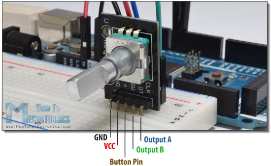
A rotary encoder looks like a metal potentiometer that you can turn clockwise or counter clockwise to increment or decrement a counter. Pressing on it also acts like a temporary push button. Encoder functionality is explained for example on howtomechatronics.
Stepper motors can also have mechanical or optical encoders attached to them, to monitor their positions.
The encoders have their own class because they use 3 digital I/O pins, and can use interrupt handlers. However the class has the same interface as the digitalIo class, for which all functions relate to the push button of the rotary encoder. For the encoder value there is one extra method.
- encoderRead(): Read the current value of the encoder
#include <digitalIO.hpp>

// Attach encoder to pins 5,4,3, limit values to [-32,32] and use interrupt handler to monitor the pins
digitalEncoder<5,4,3, -32,32, true> rotary;

void begin() { Serial.begin(9600);}

void loop()
{
   Serial.println(rotary.encoderRead());
}The example displays on the Serial port the current rotary button value when the rotary button is pressed down. To see the value as it is updated, uncomment the debug mode macro.
The example details the interface of the class and how to use it.
The Sonar class is for Ultrasonic sensors. Sonars use 2 pins, and measure distance by emmiting a ping. The class supports interrupts.
- read(u): Read the distance of the nearest object, choose units (mm, cm, inch, tenth in, sixteenth in, msec).
#include <digitalIO.hpp>

// Attach sonar to pins 4,3, and use interrupt handler to monitor the pins
digitalSonar<4,3, true> ultrasonicSensor;

void begin() { Serial.begin(9600);}

void loop()
{
   Serial.println(ultrasonicSensor.read("inch"));
}The example simply prints on the Serial console the distance measured, and changes the built-in LED to on if there's an object close by, off if there's an object far, and blinks if there's no object detected.
The example details the interface of the class and how to use it.
There's no interface needed for the basic operation. All you need to do is declare a taskManager variable for each function you want to schedule, with the period desired.
The example shows how to run 2 functions at regular intervals independently from the main loop(). The example just prints messages to the Serial console to show the loop and the two functions run at independant regular intervals.
The example details the interface of the class and how to use it.
- Fork it!
- Create your feature branch:
git checkout -b my-new-feature - Commit your changes:
git commit -am 'Add some feature' - Push to the branch:
git push origin my-new-feature - Submit a pull request
- Version 1.0 (DigitalSwitch - alpha version)
- Version 2.0 (DigitalIO - Debounce transient signals, handle output,AVR version)
- Version 2.1 digitalEncoder, digitalSonar, taskManager classes
Copyright (c) 2015-2020, Dan Truong
See the LICENCE file.