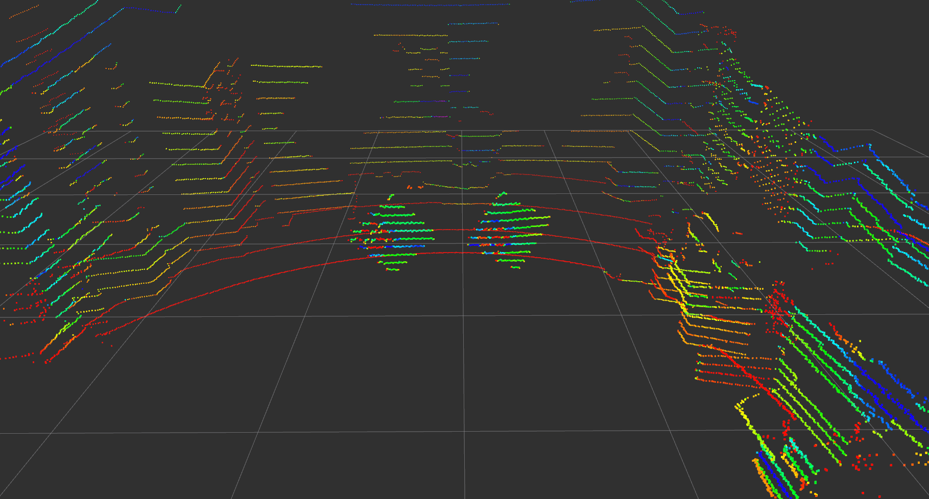
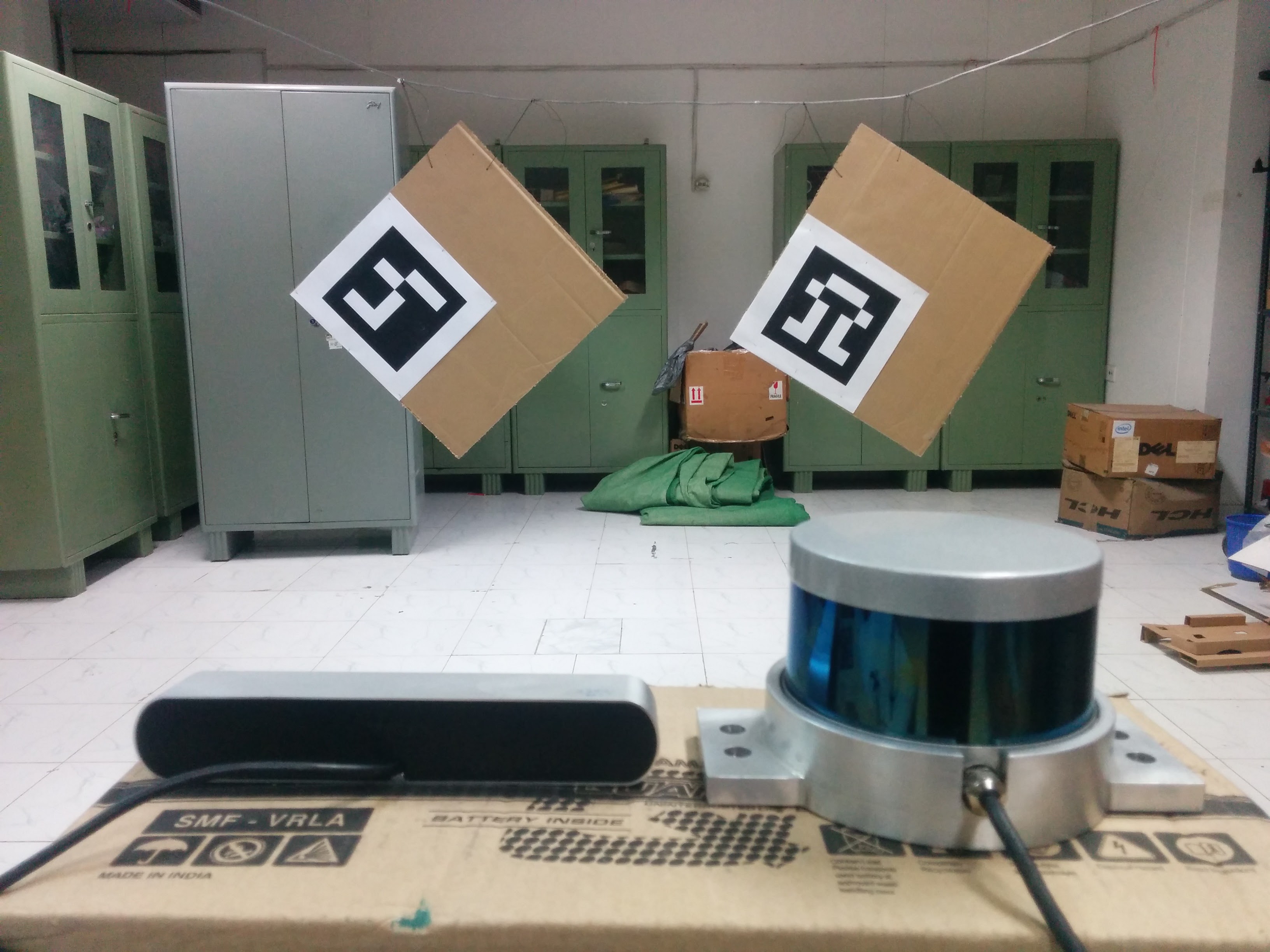
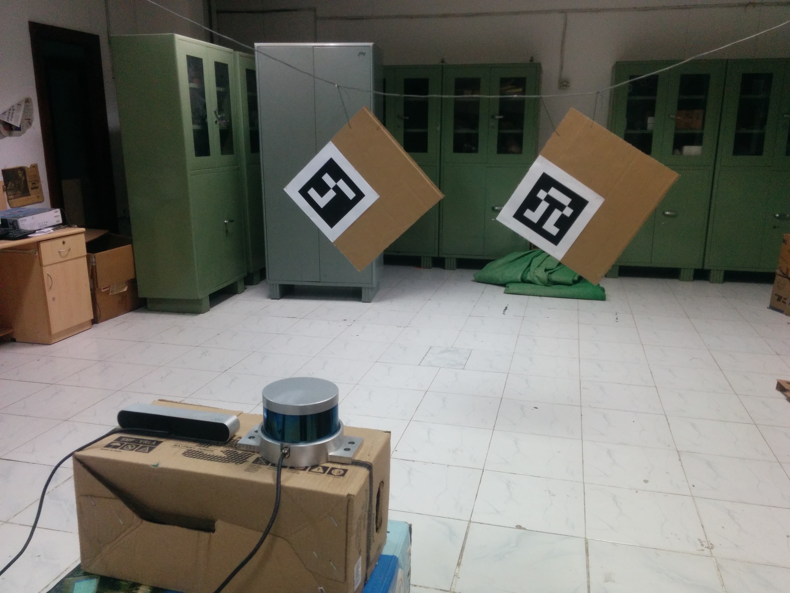
The package is used to calibrate a Velodyne LiDAR with a camera. Specficially, Point Gray Blackfly and ZED camera have been successfully calibrated against Velodyne VLP-16 using lidar_camera_calibration. Since, VLP-16 provides only 16 rings, we believe that the higher models of the Velodyne will also work well with this package.
The package finds a rotation and translation that transform all the points in the LiDAR frame to the (monocular) camera frame.
The package uses aruco_ros and a slightly modified aruco_mapping as dependencies, both of which are available in the dependencies folder in this repository.
Prerequisites:
- ROS
- aruco_ros
- a slightly modified aruco_mapping
ROS package for the camera and LiDAR you wish to calibrate.
Clone this repository to your machine.
Put the cloned repository, dependencies/aruco_ros and dependencies/aruco_mapping folders in path/to/your/ros/workspace/src and run catkin_make.
Please note that aruco_mapping in the dependencies folder is a slightly modified version of the original aruco_mapping, so make sure that you use the one provided here.
Camera parameters will also be required by the package, so it is advised that you calibrate the camera beforehand.
There are a couple of configuration files that need to be specfied in order to calibrate the camera and the LiDAR. The config files are available in the cross_sensor_calibration/conf directory. The find_velodyne_points.launch file is available in the cross_sensor_calibration/launch directory.
1280 720
-2.5 2.5
-4.0 4.0
0.0 2.5
0.05
2
0
611.651245 0.0 642.388357 0.0
0.0 688.443726 365.971718 0.0
0.0 0.0 1.0 0.0
The file contains specifications about the following:
image_width image_height
x- x+
y- y+
z- z+
cloud_intensity_threshold
number_of_markers
use_camera_info_topic?
fx 0 cx 0
0 fy cy 0
0 0 1 0
x- and x+, y- and y+, z- and z+ are used to remove unwanted points in the cloud and are specfied in meters. The filtred point cloud makes it easier to mark the board edges. The filtered pointcloud contains all points
(x, y, z) such that,
x in [x-, x+]
y in [y-, y+]
z in [z-, z+]
The cloud_intensity_threshold is used to filter points that have intensity lower than a specified value. The default value at which it works well is 0.05. However, while marking, if there seem to be missing/less points on the cardboard edges, tweaking this value will might help.
The use_camera_info_topic? is a boolean flag and takes values 1 or 0. The find_velodyne_points.launch node uses camera parameters to process the points and display them for marking. If you wish to use the camera_info topic to read off the parameters, set this to 1. Else, the explicitly provided camera parameters in config_file.txt are used.
The ArUco markers are stuck on the board such that when it is hung from a corner, the ArUco marker is on the left side of the board.
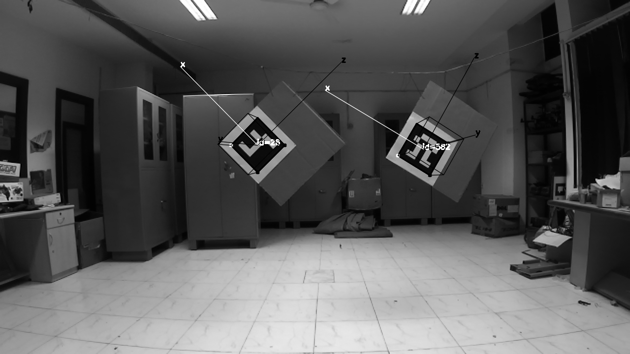
After everything is setup, it should look something like this. Notice how the axis are aligned. y-axis should point outwards, x-axis along the breadth (s2) and z-axis along the length (s1). The markers are also arranged so that the ArUco id are in ascending order.
2
48.4
46.8
4.0
5.0
20.5
49.0
46.8
4.0
5.0
20.5
After sticking the ArUco marker on a planar cardboard, it will look like this.
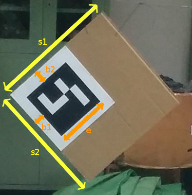
The first line specfies 'N' the number of boards being used. Followed by N*5 lines with the following information about the dimensions of the board:
length (s1)
breadth (s2)
border_width_along_length (b1)
border_width_along_breadth (b2)
edge_length_of_ArUco_marker (e)
All dimensions in marker_coordinates.txt are in centimeters.
cross_sensor_calibration:
camera_frame_topic: /frontNear/left/image_raw
camera_info_topic: /frontNear/left/camera_info
velodyne_topic: /velodyne_points
Contains name of camera and velodyne topics that the node will subscribe to.
Parameters are required for the aruco_mapping node and need to be specfied here. Ensure that the topics are mapped correctly for the node to function.
Other parameters required are:
- calibration_file(.ini format)
- num_of_markers
- marker_size(in meters)
For more information about the aruco_mapping package refer to their documentation.
A more detailed video tutorial on how to go about using the node can be found at https://youtu.be/SiPGPwNKE-Q.
Before launching the calibration node ensure that the ArUco markers are visible in the camera frame and the markers are arragned in ascending order of their ArUco ids (ArUco ids and their co-ordinate frame can be found/viewed by running the original aruco_mapping package) from left to right as viewed by the camera.
Use the following command to start the calibration process once everything is setup.
roslaunch cross_sensor_calibration find_velodyne_points.launchAn initial [R|t] between the camera and the various ArUco markers will be estimated. Following this, a filtered point cloud (according to the specifications in the config_file.txt) will be displayed. The user needs to mark each edge of the rectangular board.
Each board will have 4 line segments and need to be marked from leftmost board to the rightmost board. Marking a line segment is quite straight-forward, one needs to draw a quadrilateral around the line being marked. Click and press a key to confirm the corner of the quadrilateral. Once 4 points are clicked, each followed by a key-press, the program will move on to the next line segment. Continue marking the line segments for all boards until complete. Line segments for each board are to be marked in clock-wise order starting from the top-left.
After marking all the line-segments, the rigid-body transformation between the camera and the LiDAR frame will be displayed.
Intermediate values are logged in conf/transform.txt and conf/points.txt.
This contains the tranformation from each ArUco marker's center to the camera center. Different markers are identified by their ArUco ids. The transform is represented by 3x1 vectors, tvec and rvec. tvec is in meters while rvec follows axis-angle representation. This file is written by the slightly modified aruco_mapping node. This node runs initially and writes the tranform values, after which the pointcloud is presented to the user for marking.
This contains num_of_sensors*(num_of_markers*points_per_board) 3D points, here, num_of_sensors is fixed to 2 and the points_per_board=4, the four corner points.
So if num_of_markers = 2, then,
- the first 4 points represent the first board,
- next 4 points represent the second board,
both of which are 3D co-ordinates in meters, viewed from thelidarorigin. - the next 4 points represent the first board,
- the next 4 points represent the second board,
both of which are 3D co-ordinates in meters, viewed from thecameraorigin.
The points are ordered according to their correspondences, i.e. the second point in the first 8 points has a correspondence with the second point in the last 8 points in this case.
- automate process of marking line-segments
- iterative process with weighted average over multiple runs
