For my final year project in college, I was asked to develop an implementation of the SIMON block ciphers in VHDL, and review my design’s performance regarding logical efficiency and hardware usage. This repo was used in the development of this project. Here one can find the three VHDL designs I created, sorted into types 1, 2 and 3
I wrote 3 different versions of the same encryption system (with different properties) in VHDL (which is like a language for describing circuits), then there’s c++ code that you can compile on a Raspberry Pi which is wired up to the circuit testing board, which will use the circuit to encrypt or decrypt stuff.
Also there’s lots of testing notes, and a snazzy Java demo that uses the c++ code (which you can see in action here: https://www.youtube.com/watch?v=CTbJnPhZdKI)
.
├── documents
│   ├── demo
│   │   ├── c++
│   │   ├── files
│   │   ├── java
│   │   │   ├── monitorSide
│   │   │   └── piSide
│   │   └── vhdl
│   ├── images
│   ├── implementation
│   │   ├── samples
│   │   └── system
│   └── zybo
│
├── type_1
│   ├── computerside
│   ├── method
│   └── unified
├── type_2
│   ├── computerside
│   ├── method
│   └── unified
└── type_3
    ├── computerside
    ├── method
    ├── modeAndMethod_encryptOnly
    └── unified
The documents folder contains the demo files and handy simon-cipher related information.
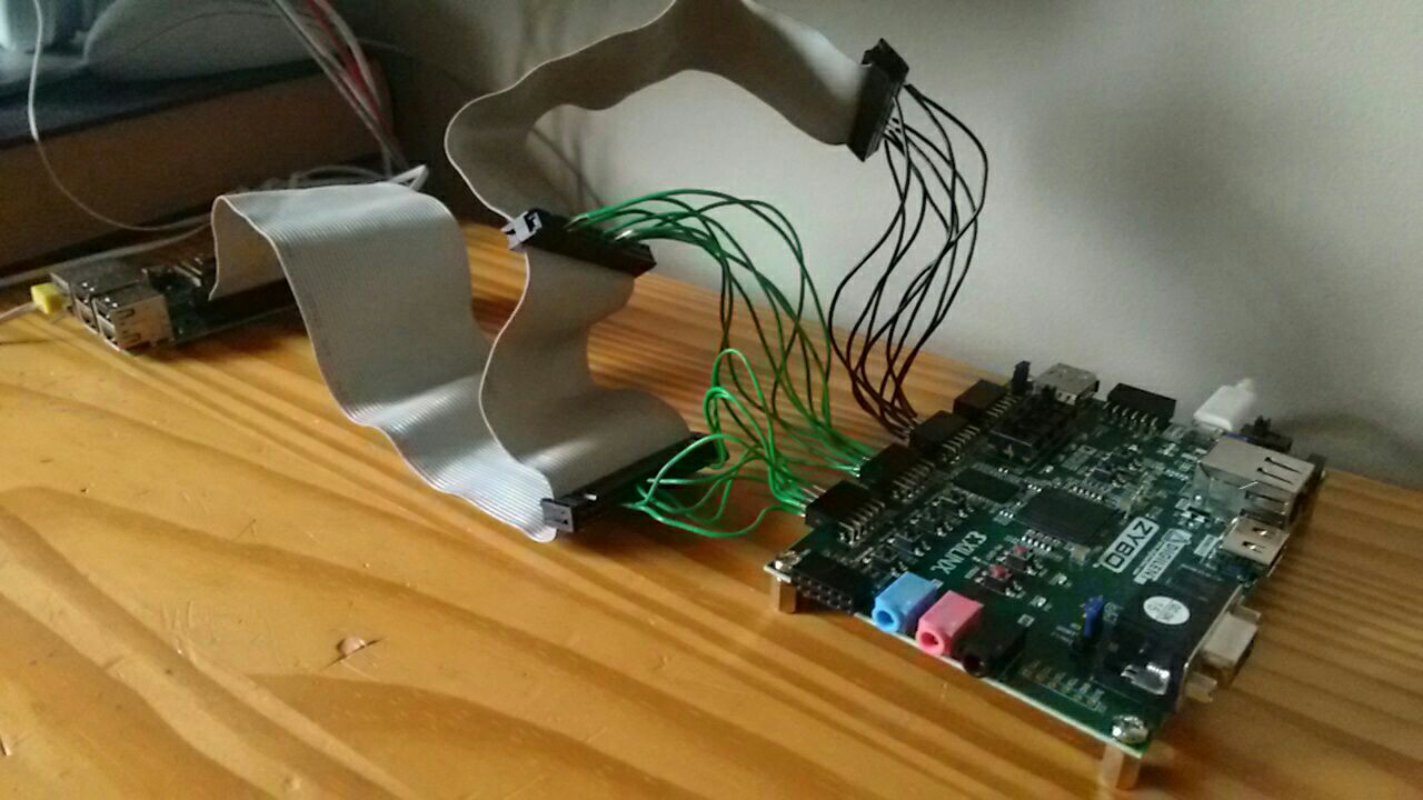
- 'demo' contains a complete set of java, c++ and VHDL files for use in demonstrating the design. One can load the VHDL design onto a development board, compile the c++ code on a Raspberry Pi (attached to the development board) and compile the Java programs on both the Pi and a display machine (networked together) The result is a pretty snazzy encryption program, which encrypts images, shows you the encrypted image, then decrypts it. You can see it in action here: Simon Encryption Java/C++/VHDL Demonstration
- 'images' is just a folder of pictures used in this document
- The 'implementation' folder is basically a hosting area for a webPaper which can be found here: webPaper.html which talks about the cipher, how the components of the cipher work, the designs I developed and some ideas of how to use the cipher, along with a large array of process samples to help others test their designs of the cipher (something I would have liked)
- 'zybo': The board I used to test my designs (and work with the Raspberry Pi) is the "Zybo Zynq-7000 ARM/FPGA Development Board", which I got on lend from my project supervisor. It's essentially a FPGA chip with alot of ports to work with (and a ARM processor, but I never used it) which I usually refer to just as "zybo" or "the development board". This folder contains a VHDL file used to connect the 24 pins of my designs to the 24 zybo pin ports. There is also a file with information about connecting the Raspberry Pi to the Zybo, and a "configuration" file used by the development software to impliment the design for this board.
Each of the "type_x" folders contain the subtype folders, along with testing notes and sometimes general notes. The subtype folers contain the actual VHDL code, which is explained later in this document. The 'testing notes' files contain information on the designs generated from the VHDL code, in regards to architecture size, estimated power usage, etc. The 'notes' files contain extra data needed to synthesize the design.
In addition; each folder contains a 'computerside' folder, which contains c++ code written for the Raspberry Pi. This code can be used to interface with the design, to encrypt messages, etc. This code is somewhat slow, as it uses the Linux file-system to access the pins. Other pin access method files are available in the demo section of the documents folder, which increases pin access speed considerably.
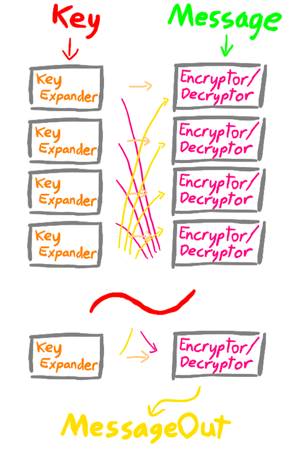
Simon is a balanced Feistel cipher, capable of encrypting blocks of data from 32bits up to 128bits in a single execution. In its most basic form, Simon is a collection of three different circuits; a key expander, a message encryptor and a message decryptor, referred to in this report as ‘modules‘. These circuits vary a little in response to the message and key bit lengths defined in the NSA’s paper, but operation is mainly the same for all. There are 10 different message and key bit lengths, defined in this paper as ‘methods’.
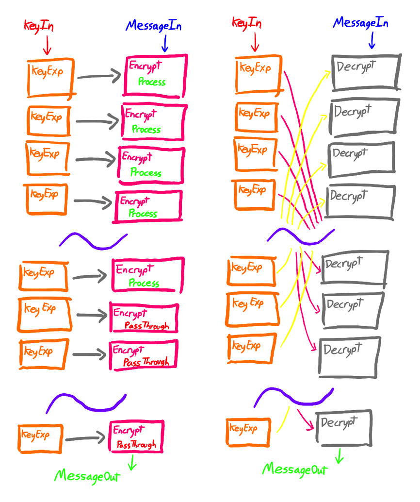
For encryption; a segment of the key provided is given to an encryption circuit along with the provided message. The circuit uses this segment to encrypt the message, producing a new message of the same length. The provided key is also mutated by a key expander circuit, producing a new key. A segment from this new key is given to another message encryptor circuit along with the message produced by the previous message encryptor circuit, producing another message.
This pattern is repeated over and over again a set number of times (defined in this paper as ‘stages’) which is defined by the method, until the message encryption is complete. Decryption is a very similar process bar two differences; first the encryption circuit is swapped for a decryption circuit, and second; the first decryption circuit needs the last mutated key (the second needing the second last, etc.) in an action akin to pushing the encrypted message backwards through the system.
As said before, the number of stages required is defined by the method;
| Method | Number of Stages |
|---|---|
| 1 | 32 |
| 2 | 36 |
| 3 | 36 |
| 4 | 42 |
| 5 | 44 |
| 6 | 52 |
| 7 | 54 |
| 8 | 68 |
| 9 | 69 |
| 10 | 72 |
The three different designs are; Flow Logic, Register Transfer Level and the Crypto-Processor. Each design is split into subtypes; unified, methods (and in design three, modeAndMethods) These different subtypes split out the functionality of the cipher, allowing a designer the ability to choose the level of encryption complexity they want, or the range of encryption functions available.
-
unified
These allow the system to encrypt or decrypt with any of the methods -
methods
These are a collection that specialize in one particular method, though allow encryption or decryption. They are much smaller than the unified version -
modeAndMethods
These are a collection that specializes in one particular method and mode. They are the smallest of the collections.
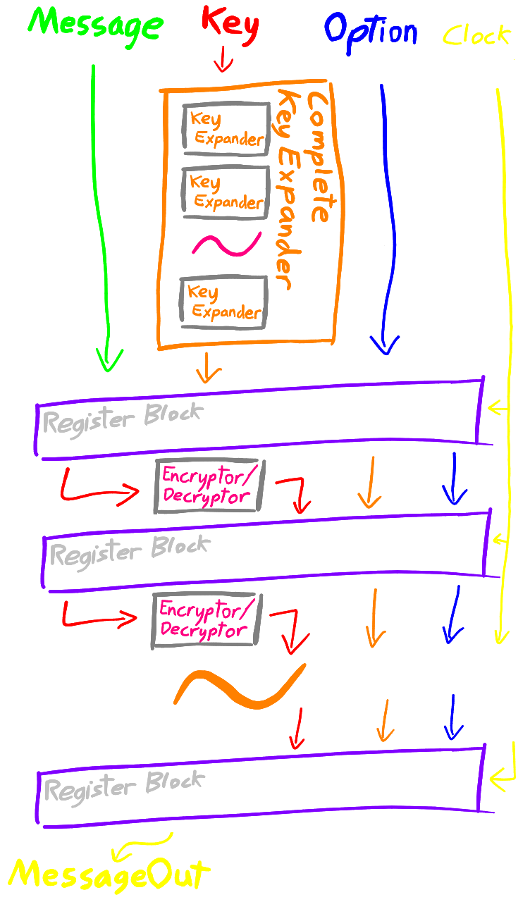
The flow logic design lays out the cipher in its entirety, allowing the user to pass data into the input and have it flow through all the required modules to produce a result. It is a pure combinational logic design, and as such no clock signal is needed. In this developed implementation, the encrypted and decrypted output is computed at the same time, with and additional ‘mode’ input determining which result to output.
Though not as optimised for through-put or size as the designs ahead; its simple layout and similarity to the basic model presented in the NSA’s paper servers as a good starting point for understanding the system.
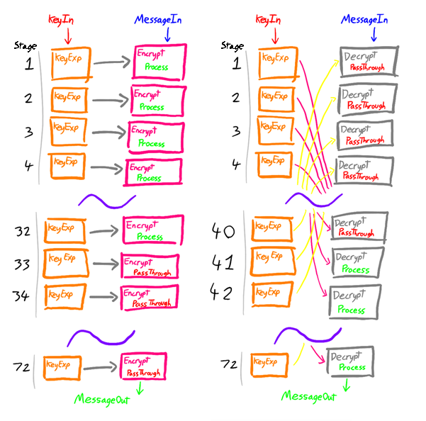
The encryption and decryption modules are tied together, so for the unified subtype an additional 4-bit input determining the method is used. This method value is passed to each encryptor/decryptor module, wherein the module can determine whether to process the message or let it pass through. This is done because the unified subtype must have enough encryptor/decryptor modules for the largest possible required stage number - 72, but different methods need a different amount of stages. Thus giving the encryptor/decryptor modules the ability to decide whether they should perform work or not, automatically adjusts the number of stages.
Though more complicated than other subtypes, devices incorporating this “multi-method” design would be able to communicate with a device using any form of the cipher.
This decision-making ability is only useful in the unified subtype and is removed in the other subtypes, where the number of stages is hardwired in. Below is a diagram of the unified subtype encrypting and decrypting a message of method 1. You can notice how the encryption and decryption modules decide whether to process the message or allow it to pass through, dependent on their position in the system.
- can allow encryption/decryption to occur in a single clock cycle, however this restricts the maximum clock frequency
- encrypting/decrypting messages with the different keys takes no longer than encrypting/decrypting with the same key
- as all the modules are being laid out in their entirety, the design takes up a large space
- much of the circuitry does nothing for the majority of the flow time
The Register Transfer Level design expands upon the previous design, addressing the issue of inactive modules. Here, every encryption and decryption module is separated out between registers, which can store the intermediate results of the encryption/decryption progress of a message. The key is completely expanded at the very first stage, and this data is passed through to the registers as well. In this way, all parts of the circuit can be utilised for processing different messages in a pipeline.
Similar to the previous design, the unified subtype has a 4-bit input determining the method to be used. This information is also stored by each register block and passes through the system alongside the message. This data is given to each encryptor/decryptor module as before.
In addition; anther one bit input connection is used. This is for the external clock, which controls the progress of the messages through the system. For every tick; a message progresses by one stage.
- multiple messages can be encrypted/decrypted in pipeline and almost simultaneously allowing for a greater throughput of messages.
- though the initial key expansion costs time; encrypting/decrypting batches of messages with the same key is quite efficient. As no key expansion time has to be factored in; the system could be run at a higher clock rate, in addition to benefiting from the near simultaneous encryption/decryption.
-
this is the largest of the designs, as not only does it contain all the circuitry of the previous design, but now there is a block of pipeline registers for each stage.
-
having the key completely expanded at the first stage can cost a lot of time, and the amount of individual registers in the register blocks required to store this information for each stage of encryption/decryption, means that the design grows quite large.
This design decision was made, as for decryption; the first decryptor module requires the last expanded key, thus the key must be expanded in its entirety before any work can begin. As the lead concept in this design was to improve flow-through in the system, the encryption mode has to run at the same speed as decryption. Thus, the initial key expansion is also done for encryption.
As you would expect, an encryption mode only subtype wouldn’t require such initial processing.
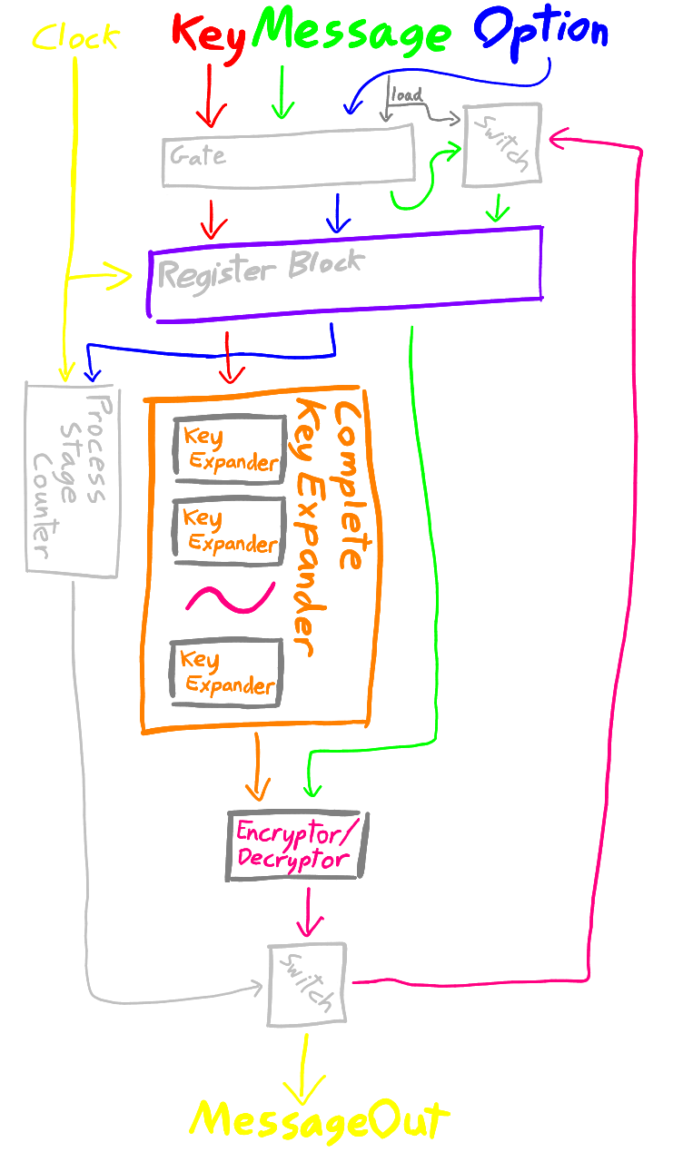
This design takes the concept of multi-staged encryption from the previous design, and distils it down into a single repeatable process. Instead of having a set of encryption and decryption modules for each stage; only one encryption and decryption module is implemented and are used repeatedly to perform encryption/decryption operations. This means that the finished implementation can take up a much smaller hardware footprint than previous designs.
Similar to the Register Transfer Level design, the provided key must be fully expanded before any encryption or decryption can begin; however this particular design contains a "modeAndMethods" subtype for encryption only, which does not need such complete key expansion time and thus only requires a fraction of the key expansion logic and registers.
Like the previous two versions, for the unified subtype an additional 4-bit input determining the method is used. This information is stored by a register block for use with the encryptor/decryptor modules similar to before. This version also has a one bit input for the external clock, which controls the progress of the messages through the system. As before, for every tick; a message progresses by one stage.
Importantly; this version has a final single bit input for loading the register block. The main package for this system splits the input message, key and control data into two register blocks; one for the incoming message, and one for the currently processing message. When the load connection is activated, the first set of data is copied into the second. In this way; the internal processing can go unaffected while a new job is loaded in.
- smallest hardware footprint
- only one message can be processed at a time
- complete key expansion time (for 'unified' and 'methods' subtypes)
Initially using an open-source simulator ‘GHDL’ to develop design one, I transitioned into using the IDE ‘Vivado’, which had the capabilities to load the designs onto the development board.
Each design and each subtype have the same basic layout. VHDL allows for a modular design, and thus the designs can easily reuse modules from each other.
Let’s take design one’s unified subtype as an example
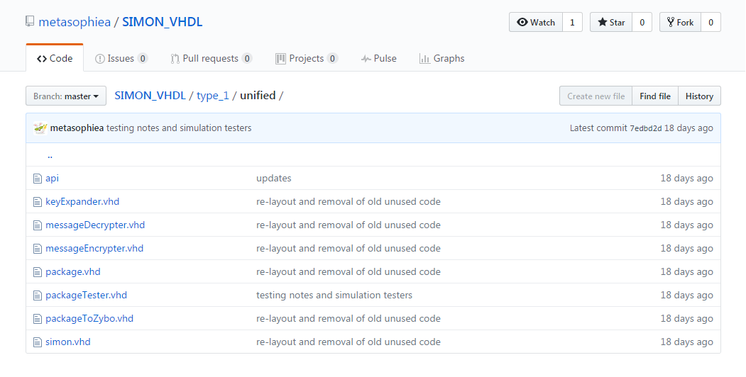
Which can be arranged like so;
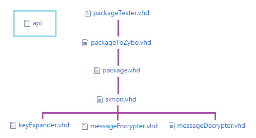
Firstly, the ‘simon.vhd’ file is the main architecture file. It uses the keyExpander, messageEncryptor and messageDecryptor modules (which are stored in VHDL files of the same name) to perform the actual encryption/decryption of any message. This architecture unfortunately has 517 input/output connections and so needs to have this number reduced to a more reasonable one for connection with an external device.
This is where ‘package.vhd’ comes in. The architecture here uses the Simon architecture as a component, and reduces the 517 connections down to 24. It is here that the ‘api’ file becomes useful. This file doesn’t contain any code; but instead a complete description of what signals need to be applied to the package architecture’s connections to access the various parts of the Simon module’s connections.
Following this, the package’s connections need to be connected to the development board’s real world connections, thus another design file is used with the package design as a component; to map the package architecture’s connections to the development board’s connections (Zybo being the short name for this board).
The final architecture file here is solely for simulation purposes. It uses the ‘packageToZybo’ architecture as a component, but produces no connections of its own. It instead utilises the simulation features of the language which allow one to test whether the architecture works properly. This file is removed before the architecture is sent to the development board.
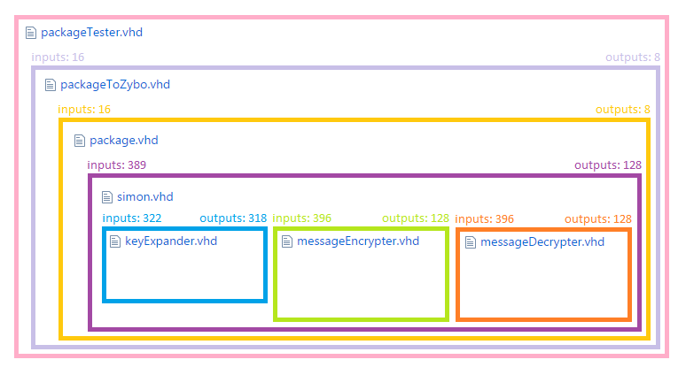
This description is actually a little misleading, as in reality the Simon architecture uses ~72 instances of the keyExpander, messageEncryptor and messageDecryptor modules, but I’ve removed them here for aesthetic purposes.
Some designs have additional architecture files. Design type two and three have a file named “completeKeyExpander.vhd”, which contains architecture that uses the keyExpander module to completely expand a key in one go. To aid the creation of subtypes other than ‘unified’, which have different methods hardcoded; a file called “constants.vhd” is used. For these implementations, all the architecture files use named constants to define how long connections should be, the size of register blocks or how many stages should be used. The values for these constants are defined in the “constants.vhd” file. Simply changing which batches of definitions are commented out adjusts the entire architecture of the system to the desired method. This was done to allow simultaneous development of each version, and so that the code repository could be much smaller overall.
As mentioned in the ‘Modularisation’ section, to communicate with the Simon cipher, one must use the APIs that the packaging architecture provided. As there were 24 connections available, they were neatly split into 3 groups of 8; the Input pins, Output pins and the Control pins.
These connections are used solely for sending data to the system.
These connections are used solely for receiving data from the system.
These connections determine what the previous two groups referred to. For example; in the case of method 1, there are 64 bits in a key. Splitting that up into groups of eight; that’s eight groups. To access group 1 (the rightmost eight bits) one must send the hex code ‘0x51’ to the control pins. Now, the eight input pins are connected to group 1, to be edited as desired.
Different codes access different parts of the key, as well as the input message. Sending the codes to access the different parts of the output message, those segments would be sent to the output pins. The codes for accessing this data are the same for all designs, subtypes and versions (though of course, for versions with smaller messages and keys; the higher access codes will return nothing)
For designs that require a clock input; the leftmost Control connection is used for connecting to an external clock (and as a result, only the right 7 bits are used for accessing the message and key segments)
In addition to connecting to the input/output messages and key; one can connect to the ‘System Option Bits’. These options are roughly the same for each subtype, and mainly allow one to set which method or mode to use. See the sections ahead for descriptions and details of each.
unused | unused | unused | method(3) | method(2) | method(1) | method(0) | mode
For this subtype; the rightmost bit controls whether the system is to encrypt or decrypt the message. The four bits to its left determine which method to use, while the rest go unused. For subtypes that had their method set; the connections for setting the method do nothing.
unused | unused | unused | method(3) | method(2) | method(1) | method(0) | mode
For this subtype; the rightmost bit controls whether the system is to encrypt or decrypt the message. The four bits to its left determine which method to use while the rest go unused. For subtypes that had their method set; the connections for setting the method do nothing.
unused | unused | load | method(3) | method(2) | method(1) | method(0) | mode
For this subtype; the rightmost bit controls whether the system is to encrypt or decrypt the message. The four bits to its left determine which method to use, while the bit to their left activates the load function and the rest go unused. For subtypes that had their method or/and mode set; the connections for setting the method/mode do nothing.
This code is used to communicate with the zybo device correctly, with the communication rules set out in the hardware API. It has all the test messages from the NSA paper preloaded for testing, and can send these to the system to gather an encrypted or decrypted result. The user then must decide whether the process has been a success or not. In addition, other messages can be entered into a console interface and sent to the system for further tests. Thanks to the similarity of the APIs, the C++ tester program is roughly the same for each design, subtype and version. It’s split up into six sections;
This section consists solely of hexadecimal/binary conversion functions, in both directions.
Here, you can find all the low-level functions that work with the Linux file system to set-up and work with the Raspberry Pi GPIO pins. Reducing the complexity down to a couple of simple “set pin x to y” and “read pin z” functions.
Located here, are the main functions for dealing with the system. Abstracting things further, this section uses the functions from above to create “setControl”, “setInput” and “readOutput” functions that can take/return strings of hexadecimal. Building on this, there are functions “writeModeAndMethod”, “writeKey” and “readMessage” which can send and receive entire messages and keys to the system.
This section is more changeable between versions, depending on how interaction must be performed with the system (such as sending clock signals, etc.) Here is a single function, with which one can provide the mode, method, key and message, and receive the complete response message as a string. This function is the main manager of encryption; sending the key, message and options to the system, providing clock and load signals (if necessary) and reading the returned message back.
Similar to the section above, though a little more experimental; this section contains a function that takes mode, method, key and a file address. The function will then open said file, and encrypt or decrypt its contents, creating an output file in the same directory. This function is deemed experimental, as it isn’t as finished as other sections, and can only take files that have a certain data format. It exhibits however, that with a little work it is entirely possible to have a program that could take any file and encrypt it.
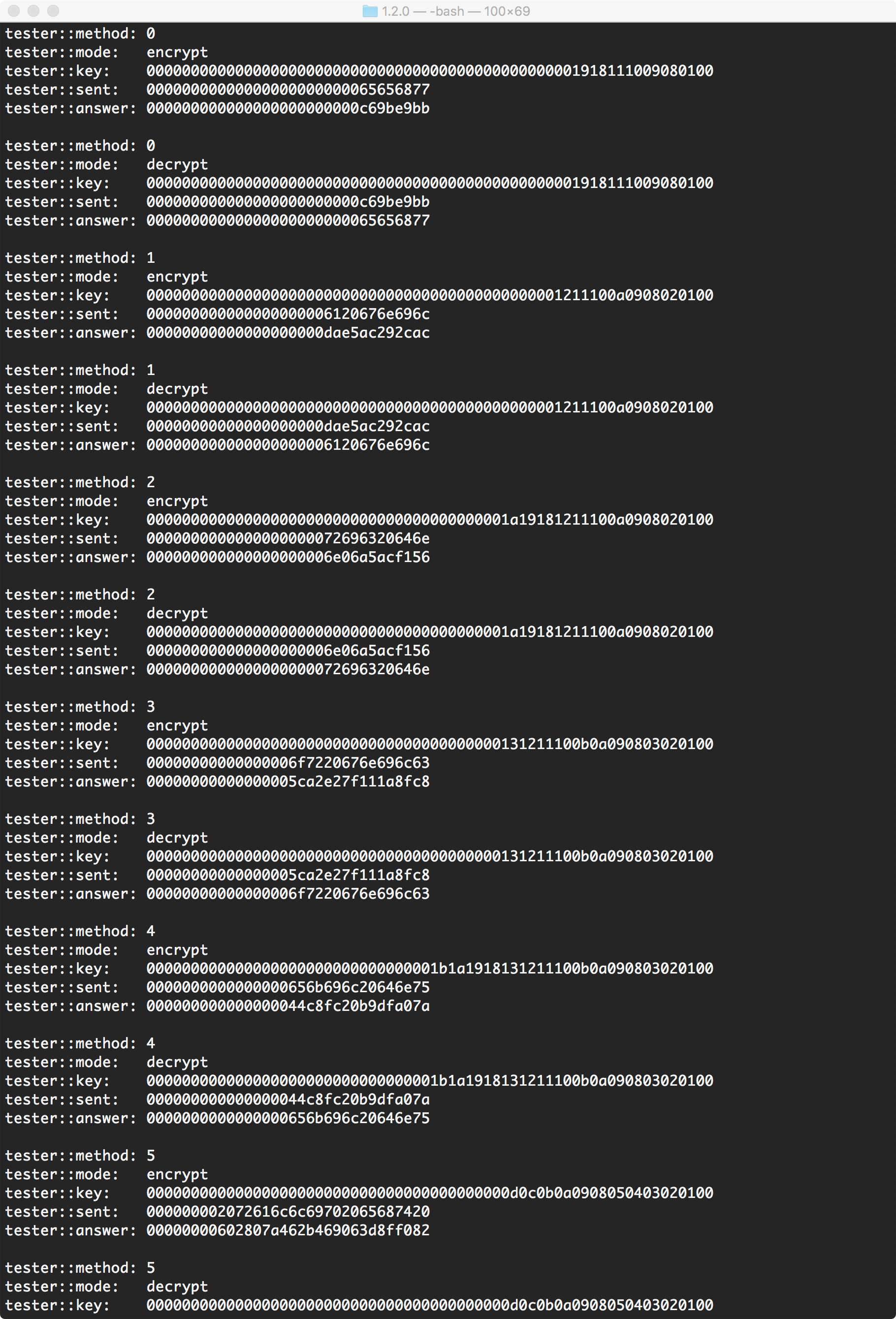
The lead section, this code runs a console program with which a user can provide the key and message they wish to encrypt or decrypt. It also contains all the test messages from the NSA paper. Below, is a screenshot of the console output of this testing on a unified subtype
The code used in each computerside folder of each type, accesses the Raspberry Pi's pins through the Linux file system. Though safer to use this is quite slow. Within ./documents/demo/c++ one can find files labled raspberryPI_api_SYSFS.cpp, raspberryPI_api_wiringPi.cpp and raspberryPI_api_DRA.cpp. Though all contain the same functions; each file accesses the Pi's pins differently, using the Linux file system as before, wiringPi by Gordon Henderson and Direct regiester access by Gert van Loo & Dom respectivly (with code taken from http://elinux.org/RPi_GPIO_Code_Samples)
The second two files run much faster than the file system methods, and I recomend them for actual use, though the file system method is very handy for testing
- YouTube demo video: https://www.youtube.com/watch?v=CTbJnPhZdKI
- Simon web paper: http://metasophiea.com/projects/simon/webPaper.html
- Project Report: documents/finalReport_20170529.pdf