Advanced Lane Finding Project
The goals / steps of this project are the following:
- Compute the camera calibration matrix and distortion coefficients given a set of chessboard images.
- Apply a distortion correction to raw images.
- Use color transforms, gradients, etc., to create a thresholded binary image.
- Apply a perspective transform to rectify binary image ("birds-eye view").
- Detect lane pixels and fit to find the lane boundary.
- Determine the curvature of the lane and vehicle position with respect to center.
- Warp the detected lane boundaries back onto the original image.
- Output visual display of the lane boundaries and numerical estimation of lane curvature and vehicle position.
Here I will consider the rubric points individually and describe how I addressed each point in my implementation.
1. Briefly state how you computed the camera matrix and distortion coefficients. Provide an example of a distortion corrected calibration image.
The code for this step is contained in lines 13 through 101 of the file called calibration_functions.py.
I start by preparing "object points", which will be the (x, y, z) coordinates of the chessboard corners in the world. Here I am assuming the chessboard is fixed on the (x, y) plane at z=0, such that the object points are the same for each calibration image. Thus, objp is just a replicated array of coordinates, and objpoints will be appended with a copy of it every time I successfully detect all chessboard corners in a test image. imgpoints will be appended with the (x, y) pixel position of each of the corners in the image plane with each successful chessboard detection.
I then used the output objpoints and imgpoints to compute the camera calibration and distortion coefficients using the cv2.calibrateCamera() function. I applied this distortion correction to the test image using the cv2.undistort() function and obtained this result:
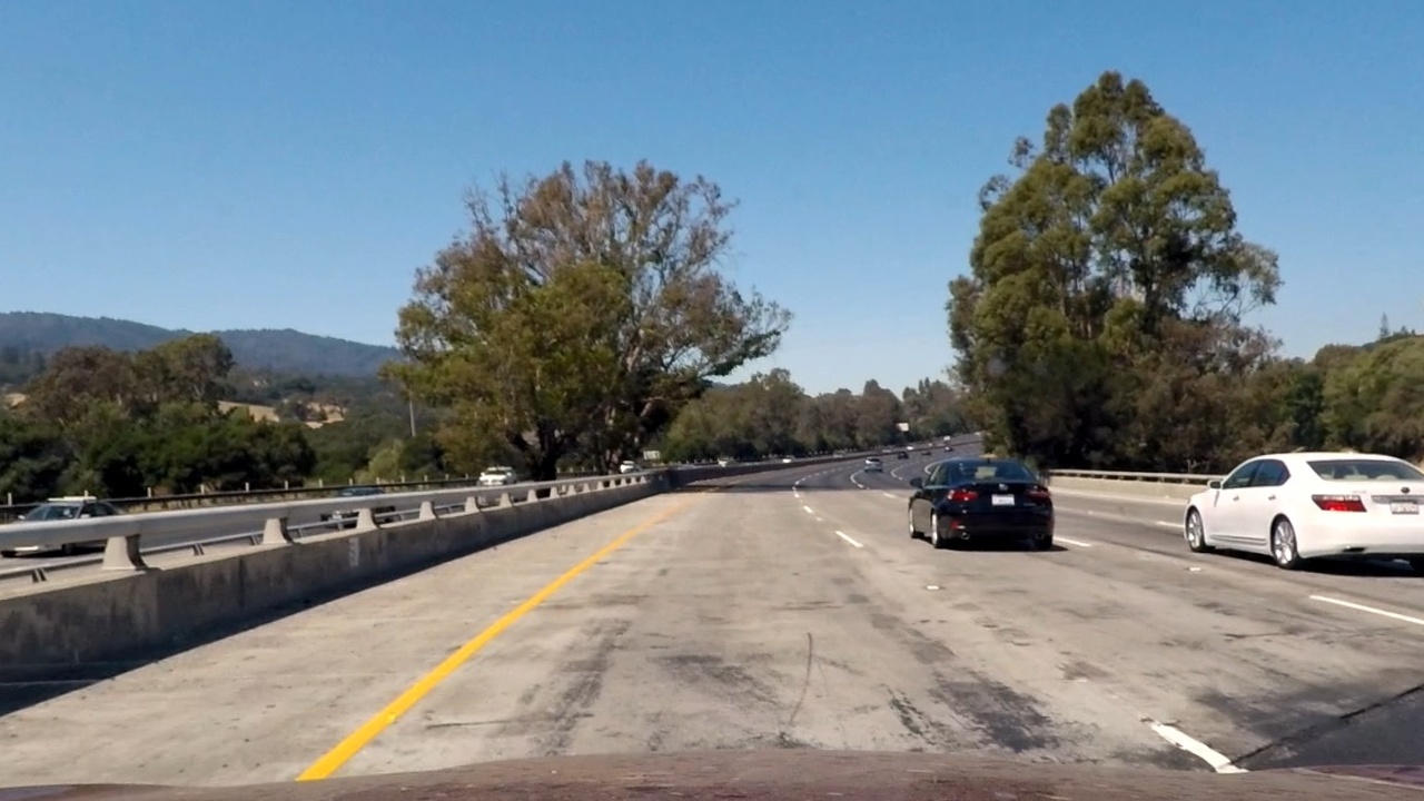
To demonstrate this step, I will describe how I apply the distortion correction to one of the test images like this one:
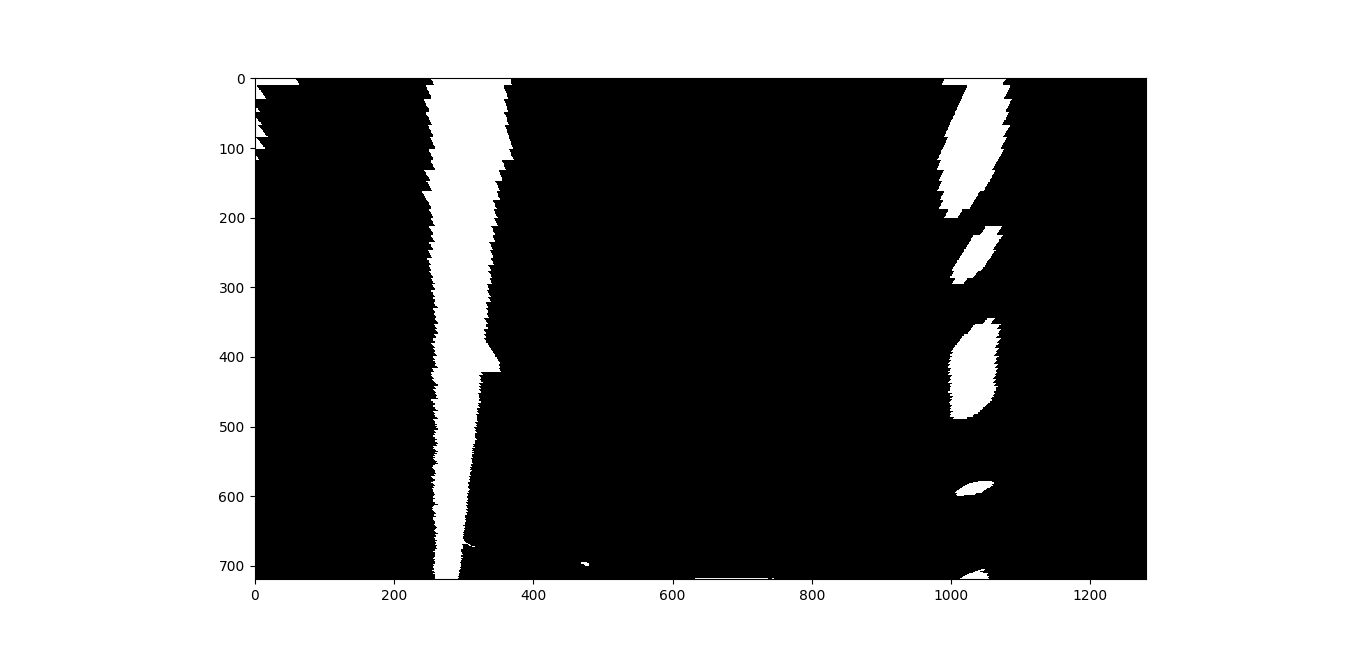
2. Describe how (and identify where in your code) you used color transforms, gradients or other methods to create a thresholded binary image. Provide an example of a binary image result.
I used a combination of color and gradient thresholds to generate a binary image (thresholding steps at lines 10 through 322 in threshold_functions.py). Here's an example of my output for this step.
![alt text][image64]
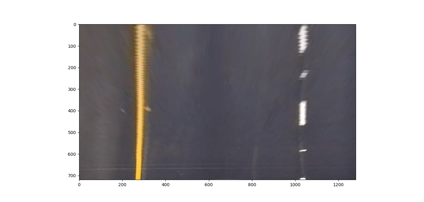
3. Describe how (and identify where in your code) you performed a perspective transform and provide an example of a transformed image.
The code for my perspective transform includes a function called birdview(), which appears in lines 11 through 45 in the file perspective_function.py. The birdview() function takes as inputs an image (img), but source (src) and destination (dst) points are hardcodeed within the function in the following manner:
    src = np.float32([[896., 675.],
                      [384., 675.],
                      [581, 460],
                      [699, 460]])
    dst = np.float32([[896., 720.],
                      [384., 720.],
                      [280., 0.],
                      [1024., 0.]])
This resulted in the following source and destination points:
| Source | Destination |
|---|---|
| 896, 675 | 896, 720 |
| 384, 675 | 384, 720 |
| 581, 460 | 280, 0 |
| 699, 460 | 1024, 0 |
I verified that my perspective transform was working as expected by drawing the src and dst points onto a test image and its warped counterpart to verify that the lines appear parallel in the warped image.
Binary:
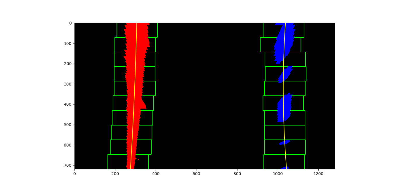
4. Describe how (and identify where in your code) you identified lane-line pixels and fit their positions with a polynomial?
Then I did some other stuff and fit my lane lines with a 2nd order polynomial, which appears in lines 14 through 414 in the file lines_functions.py. its output shows as follows:
I declared a class class Line(): whcih I used for both left and right lanes. The class contains multple variables and sub-functions, to easily exract info for each line, and also to collect info about each line identified. so that it can be used later on incase a line was not detected or not having enough data.
Once I am able to detect the lane points, I use cv2.polyfit() to find a 2nd polunomial function that fits withinn those points.
I also used that stack of detected lines to smooth the output and speedup the process, where If lanes were detected in previous frame, then I use the old data to start looking for lanes at dame loctation where the lane was in the privius frame.
5. Describe how (and identify where in your code) you calculated the radius of curvature of the lane and the position of the vehicle with respect to center.
I did this in lines 98 through 100 in my code in lines_functions.py
I have to property functions within the class Line():, so that its easier to get the curveture for a specific line insted of passing the line data outside to another finction to calculate the curveture.
I have 2 properties, radius of curvature of the line in pixels and radius of curvature of the line in meters:
    @property
    # radius of curvature of the line in some units
    def radius_of_curvature_pixels(self):
        y_eval = 0
        coeffs = self.best_fit_pixels
        return ((1 + (2 * coeffs[0] * y_eval + coeffs[1]) ** 2) ** 1.5) / np.absolute(2 * coeffs[0])

    @property
    # radius of curvature of the line in some units
    def radius_of_curvature_meters(self):
        y_eval = 0
        coeffs = self.last_fit_meter
        return ((1 + (2 * coeffs[0] * y_eval + coeffs[1]) ** 2) ** 1.5) / np.absolute(2 * coeffs[0])
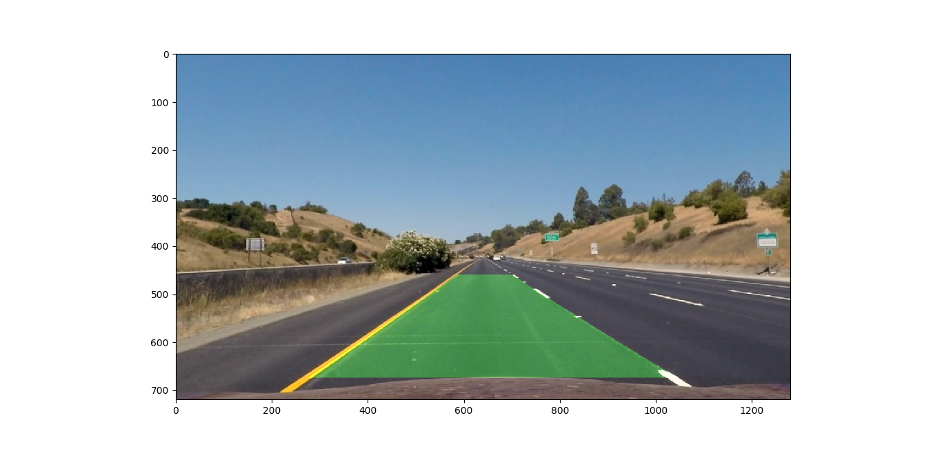
6. Provide an example image of your result plotted back down onto the road such that the lane area is identified clearly.
I implemented this step in lines 375 through 414 in my code in lines_functions.py in the function unwarp_lines(). Here is an example of my result on a test image:
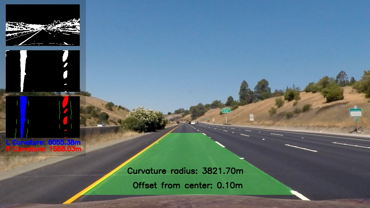
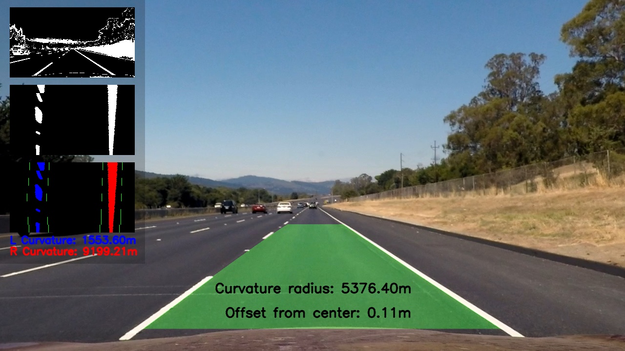
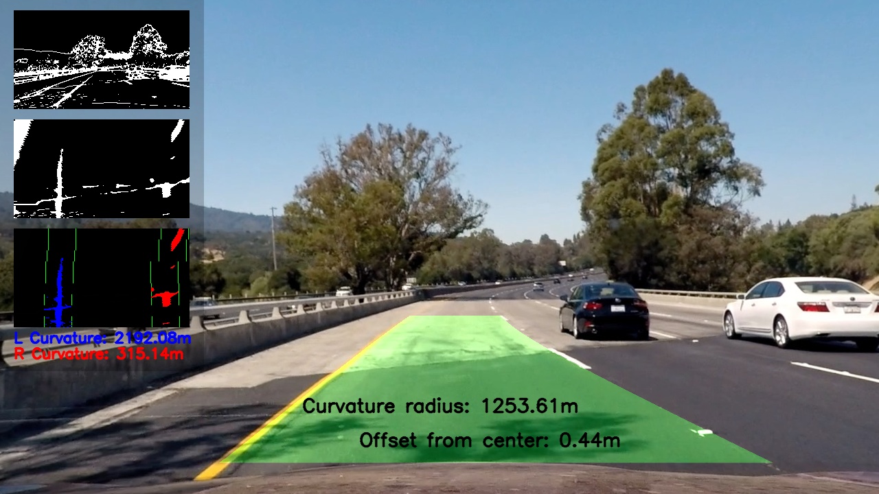
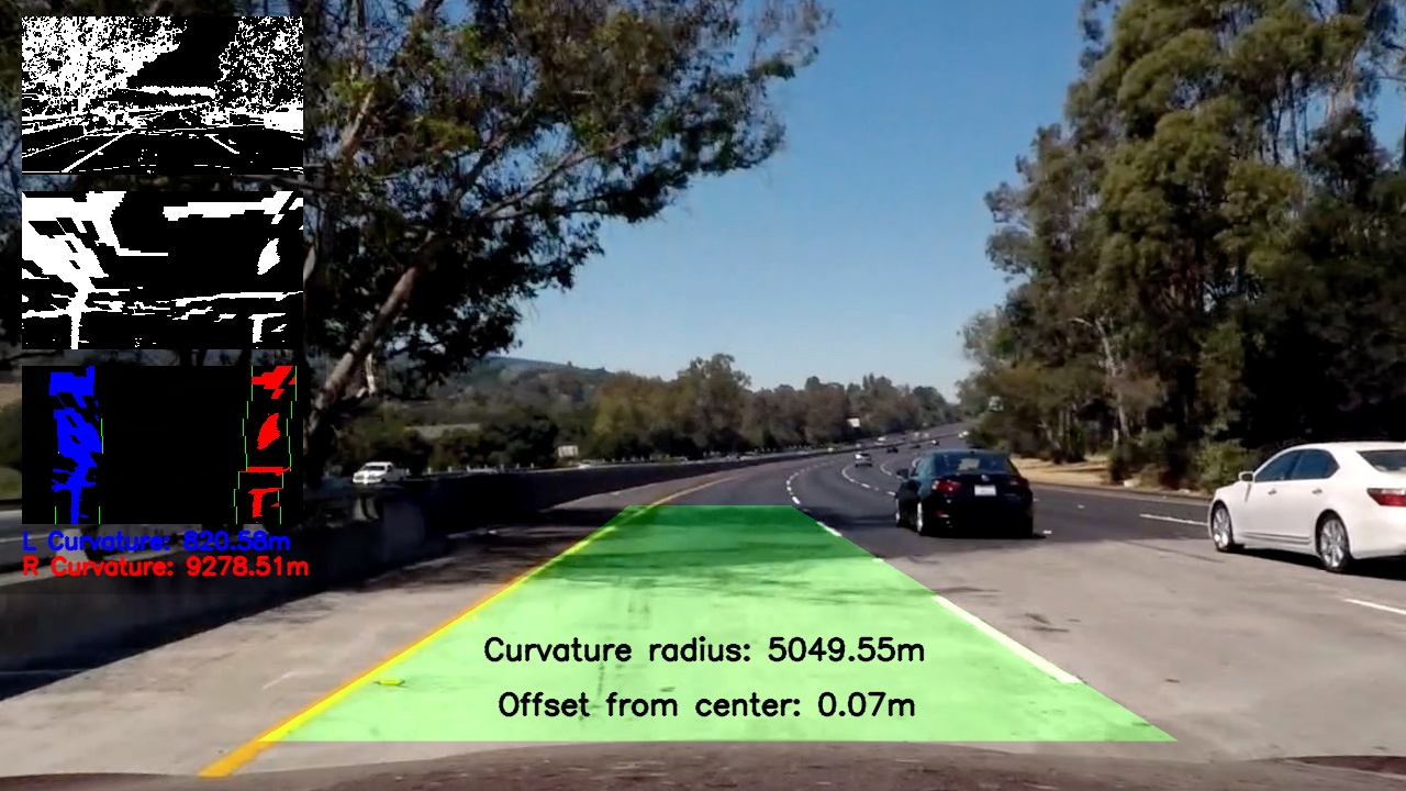
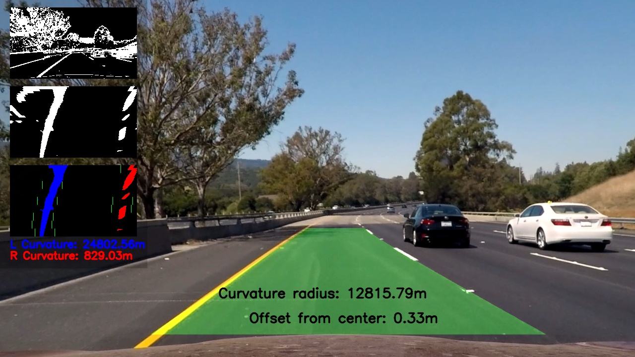
7. After passing the image through all the pipleline steps, I blended some usful images and info to the image like the binary output and detected lanes. In addition I blended the lane curveture and center offset to the image as follows:
1. Provide a link to your final video output. Your pipeline should perform reasonably well on the entire project video (wobbly lines are ok but no catastrophic failures that would cause the car to drive off the road!).
Here's a link to my video result
1. Briefly discuss any problems / issues you faced in your implementation of this project. Where will your pipeline likely fail? What could you do to make it more robust?
-
Finding the source and destination for perspective transformation was hard, and included alot of trial and error. Probably more information about the location and angle of the camera can help more in transfoming the image into the bird view.
-
I had to use diffirent filters to avoid the shaddows effect when I try to detect the lanes, Smoothing the lines by using previous data detected in previous frames helped in speeding the process time and cut-off the jitter from the video.
- My pipline will fail the challange videos, where my thrshold filters need more tuning, probably the use of
TOP HATwould be better for detectiong the shodow area.
-
Avraging of polynomials is good for clean wide angle lanes, But when sharp curveture happens with shaddows or bright area happens we need more robust approch. One thing I can think of , is if we detect one side of the lane and we have high confidance that it is, with the old dta of the missing side we can approximate what the properties of the missing line can be.
-
I need to better understand the filters and there effect on the images, and also dig deeper to the diifferent image filters. Their might be better ones that can help get better results and give more accurate output.


