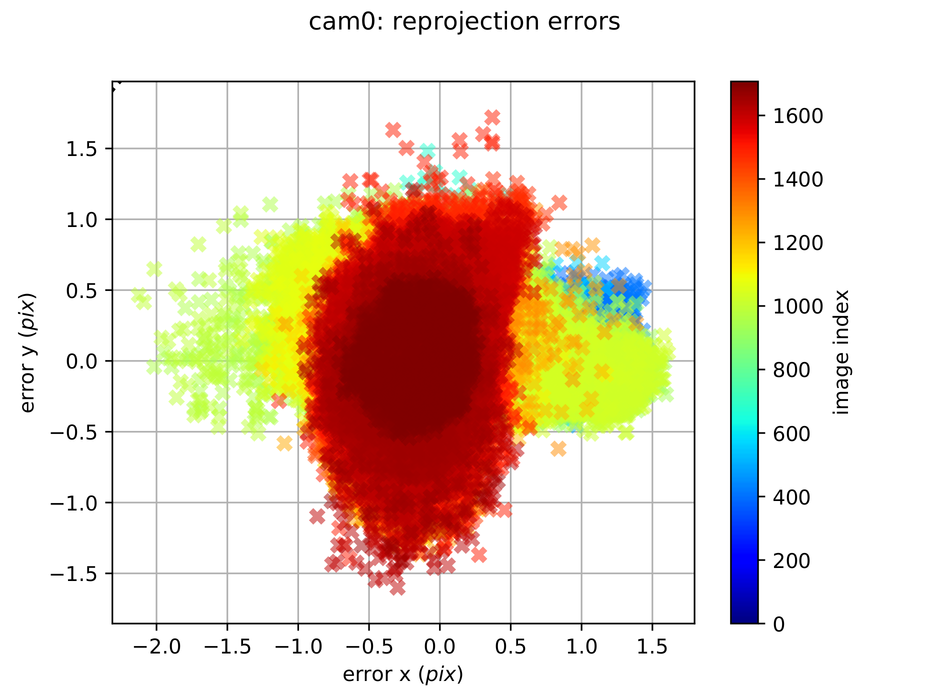
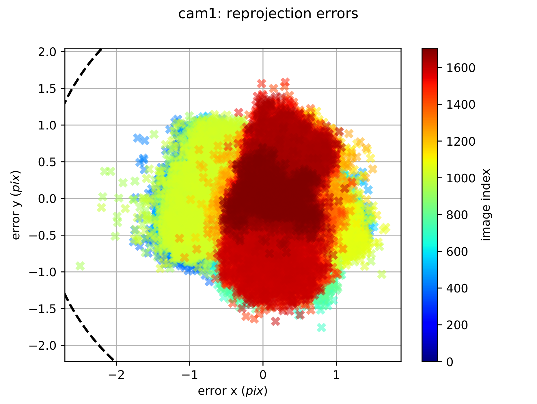
An open-source toolbox for users to have easy access to Hardware Synchronization on multi-sensors. The toolbox has a GUI based on QT (RQT). Users can record a ROS bag or have a new topic reflector (reconstructed timestamp) as they want. Furthermore, the hardware-level IMU data process is also embedded in Microcontroller.
This toolbox, together with the MPL Calibration Toolbox, the MPL Dataset Toolbox, and the k4a Projector, is available as open-source under the terms of the BSD-3-Clause-Clear License. If you use this toolbox in an academic context, please cite the publication as follows:
@Article{gao2022vector,
  author  = {Gao, Ling and Liang, Yuxuan and Yang, Jiaqi and Wu, Shaoxun and Wang, Chenyu and Chen, Jiaben and Kneip, Laurent},
  title   = {{VECtor}: A Versatile Event-Centric Benchmark for Multi-Sensor SLAM},
  journal = {IEEE Robotics and Automation Letters},
  pages   = {8217--8224},
  volume  = {7},
  number  = {3},
  year    = {2022},
  doi     = {10.1109/LRA.2022.3186770}
}Environment(Host): Ubuntu 20.04(ros-noetic)
sudo apt-get install libqt5serialport5-dev
mkdir -p ~/catkin_ws/src && cd ~/catkin_ws/src
git clone git@github.com:sjtuyuxuan/sync_toolbox.git
cd ~/catkin_ws && catkin_make
source ~/catkin_ws/devel/setup.bashFirst, connect the boot loader line and set the PIC-32 to boot loader mode.
Second, find the serial port name (usually is /dev/ttyUSB0)
Third, set the makefile MACRO (more detail in 'http://hades.mech.northwestern.edu/index.php/ME_333_Introduction_to_Mechatronics')
Forth, run the commend
make writeTBD
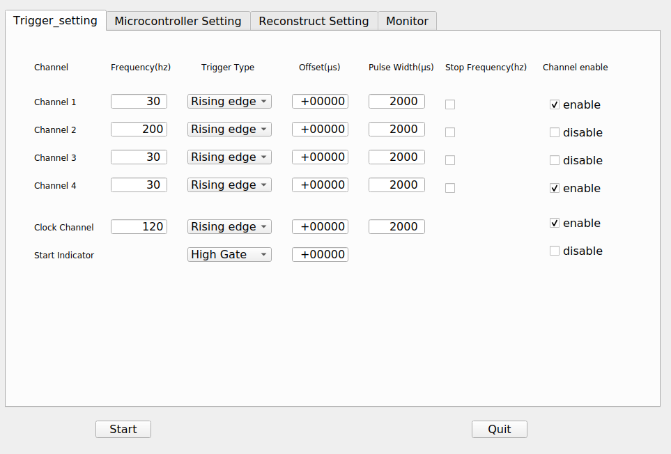
There are 4 general channel + 1 clock channel + 1 start indicate channel.
General sensor trigger channel have three mode raising edge, falling edge, and double edge mode.
Frequency is from 1 - 999 Hz
Offset is in unit of us, which can be positive (later than standard time) or negative.
Pulse width is also in unit of us. Notice that it is disabled when double edge mode is checked.
General channel is started synchronized when the start button is clicked.
Clock channel channel is similar to General channel but start when the microcontroller is set.
The channel is usually used as a clock reference.
Start indicator channel is used together with clock channel to mark the start and end signal to other device.
There is high gate, low gate, and double pulse mode.
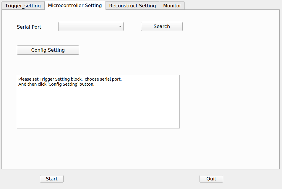
First, click search button and find the correct serial port for microcontroller.
Second, click the config setting button.
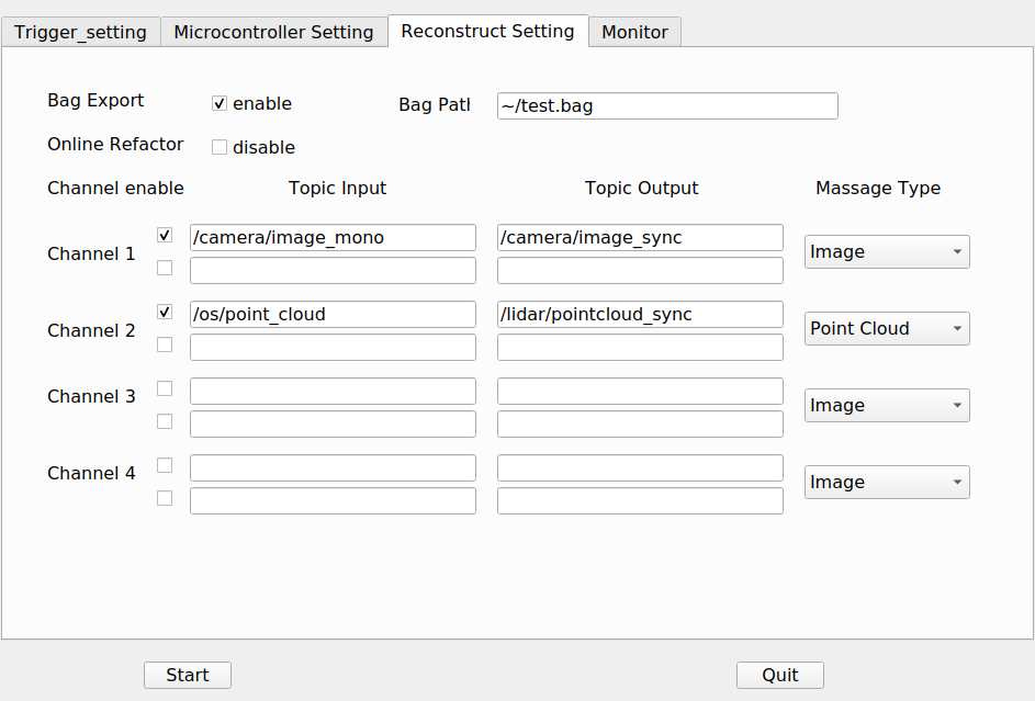
There are two ways to use the timestamps reconstruction: Bag export and online reflector.
Each General channel have two topic could be reconstructed independently (stereo case).
There are four default massage type. Image, Point Cloud, Imu, and PoseStamped.
The massage content will not changed. Only the header will changed.
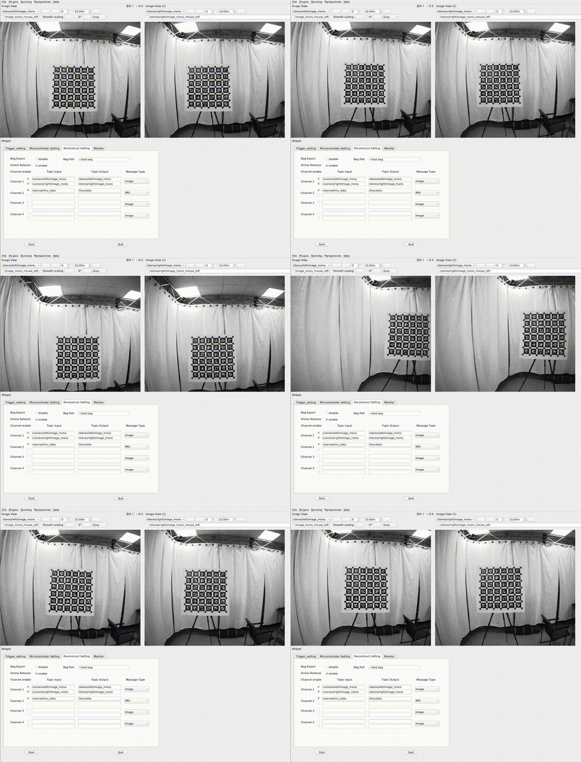
Click the start button and start recording data.
- 2xGrasshopper usb3 camera (1224x1024, 30Hz, global shutter)
- XSense Mti300 IMU (9-axis, 200Hz)
- Motion Capture System
cam0:

T_cam_imu:

\- [0.017248643674008135, -0.9998037138739959, 0.009747718459772736, 0.07733078169916466]

\- [0.012834636469124028, -0.009526963092989282, -0.999872246379971, -0.016637889364465353]

\- [0.9997688514842376, 0.017371548520172697, 0.01266779001636642, -0.14481844113148515]

\- [0.0, 0.0, 0.0, 1.0]

camera_model: pinhole

distortion_coeffs: [-0.31576, 0.104955, 0.00032, -0.000156]

distortion_model: radtan

intrinsics: [886.191073, 886.591633, 610.578911, 514.59271]

resolution: [1224, 1024]

rostopic: /stereo/left/image_mono

**timeshift_cam_imu: 0.005375665182111344**
cam1:
T_cam_imu:
\- [0.014447870885660574, -0.9997787221387724, -0.015289401081614196, -0.09375829054484337]
\- [0.01108843210124949, 0.015450259055501236, -0.9998191517312787, -0.015076213124111792]
\- [0.9998341390952836, 0.014275722527461954, 0.011309201824693582, -0.14050229888646543]
\- [0.0, 0.0, 0.0, 1.0]
camera_model: pinhole
distortion_coeffs: [-0.311523, 0.09641, 0.000623, -0.000375]
distortion_model: radtan
intrinsics: [887.804282, 888.04815, 616.177573, 514.712952]
resolution: [1224, 1024]
rostopic: /stereo/right/image_mono
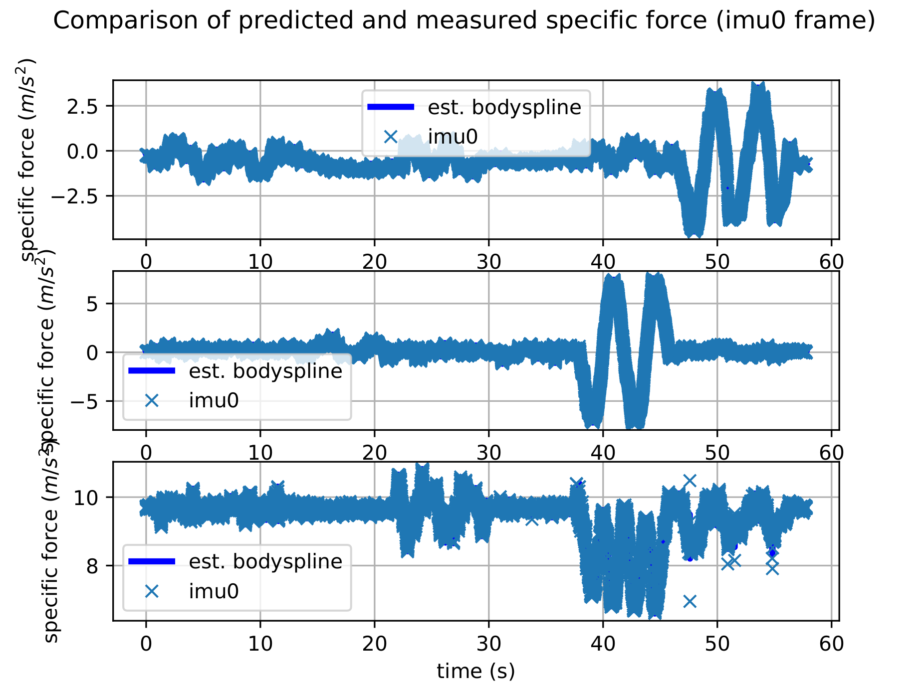
**timeshift_cam_imu: 0.005415704144667583**The timeshift from camera and imu is near 5ms which is in line with our expectations. Because we set start point aligned and the exposure time is 10ms.

