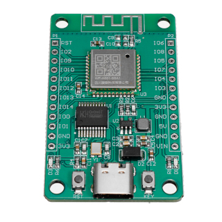
Hi3861 is a 32-bit risc-v microcontroller, made by Huawei/HiSilicon.
- 160 MHz
- 288 kbyte rom
- 352 kbyte ram in total, 280 kbyte ram available for user programs
- 2 mbyte flash
- WiFi
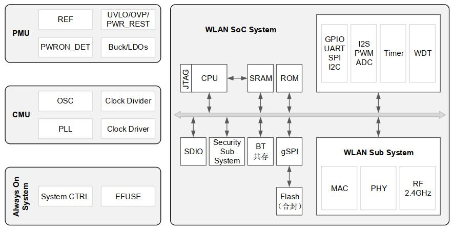
This is a block diagram of the Hi3861 processor. External components are a 40MHz crystal, a 32768 Hz crystal, and a pcb antenna. Flash memory is connected via spi. The HI3861 has 2 Mbyte flash memory.
The HI3861 shares die with the HI3881 wifi video camera. The HI3881 IP camera version does not have spi flash memory. The HI3881 runs software from rom.
This is the memory map of the Hi3861. 保留 = reserved.
- RAM (rx): ORIGIN = 0x000D8000, LENGTH = 280K
- ROM (rx): ORIGIN = 0x003B8000, LENGTH = 288K
- FLASH (rwx): ORIGIN = 0x00400000, LENGTH = 16M
16 Mbyte address space is mapped to spi flash, but the HI3861 spi flash is only 2 Mbyte in size.
| pin | jtag | |
|---|---|---|
| IO00 | JTAG_TDO | |
| IO01 | JTAG_TCK | |
| IO02 | JTAG_TRSTN | |
| IO03 | JTAG_TDI | |
| IO04 | JTAG_TMS | |
| IO06 | JTAG_MODE | |
| IO08 | JTAG_ENABLE | Pull high |
If pin IO8 is low at power-up, pins IO0...IO4 are normal GPIO pins. If pin IO8 is high at power-up, pins IO0...IO4 are used for JTAG.
If JTAG_ENABLE is high at power-up, pins IO03, IO04 are used for JTAG. If JTAG_ENABLE is low at power-up, pins IO03, IO04 are used as console serial port RX, TX pins. Conflict is possible if using usb serial and JTAG at the same time.
| Pin | Default state | Low level | High level |
|---|---|---|---|
| IO2/REFCLK_FREQ_STATUS | Pull down | 40MHz (Default) | 24MHz |
| IO6/JTAG_MODE | Pull down | Normal function mode (Default) | DFT Test mode |
| IO8/JTAG_ENABLE | Pull down | Ordinary IO (Default) | JTAG enable |
 |
 |
|---|---|
| front | back |
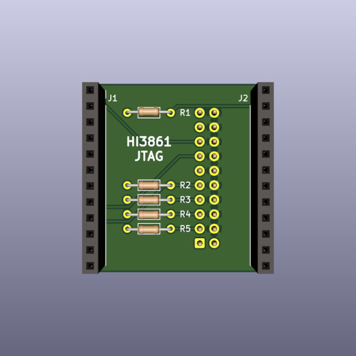
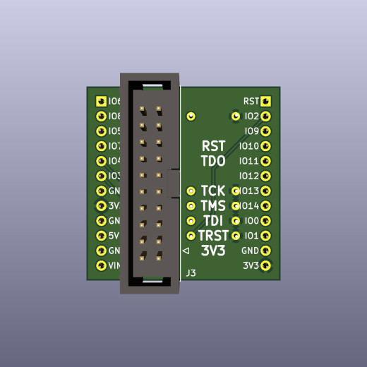
A small circuit is needed to enable the JTAG interface. The adapter board plugs in on the back of the Hi3861 module. This adapter board can be soldered by hand.
The boot process of Hi3861 consists with three parts: romboot, flashboot and kernel (user code, or the OS itself).
- The fixed romboot verifies the flashboot at
FLASH_BASE, copies the flashboot to0x10A000(which is actuallyCPU_RAM_BASE + 200KB) and executes. Since the first 64 bytes in the bootable image is the signature header, the actual entry is0x10A040 - The flashboot then verifies and boots the kernel at
FLASH_BASE + 0xD3C0.
A full build of LiteOS generates several images. Finally a Hi3861_demo_allinone.bin can be imported to the HiBurn tool to flash. Here is a flow chart of the build progress:
Though not documented, the signature header is simple. There is an open source signing tool in Python: sign_bin.py
Tools to flash firmware: hiburn, openocd, jlink.
The tool to download firmware to the HI3861/HI3881 through the serial port is called hiburn. There is a hiburn from Huawei, and there are open source versions. These are different tools that share the same name.
- Hiburn is a Windows tool from Huawei for downloading firmware via the serial port.
- The Zephyr project has an open source alternative for Hi3861.
The protocol to flash Hi3861 is a combination of a private command procotol and Ymodem. Though the client side (HiBurn) is not open source, we can see how the protocol looks from the server side: loaderboot from the LiteOS/OpenHarmony SDK. Just like the flashboot, the entry of the loaderboot is at 0x10A040.
For hiburn to work, LiteOS or OpenHarmony needs to contain the u-boot feature.
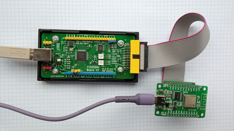
The openocd directory contains configuration files for the open source tool openocd. This is what I use to download firmware to a Hi3861 board. Needs a FT2232 module, and the JTAG adapter above.
To build openocd with risc-v extensions:
sudo apt-get build-dep openocd
git clone https://github.com/riscv/riscv-openocd
cd riscv-openocd
./bootstrap
./configure --prefix=/opt/riscv-openocd
make
make install
To use openocd as gdb server:
/opt/riscv-openocd/bin/openocd -f ./interface/hi-ft2232d-ftdi-jtag.cfg -f ./target/hi3861-jtag.cfg
...
Info : clock speed 500 kHz
Info : JTAG tap: hi3861.cpu tap/device found: 0x0000076d (mfg: 0x3b6 (HiSilicon Technologies), part: 0x0000, ver: 0x0)
Info : [hi3861.cpu] datacount=1 progbufsize=3
Info : Disabling abstract command reads from CSRs.
Info : Examined RISC-V core; found 1 harts
Info :  hart 0: XLEN=32, misa=0x40901104
[hi3861.cpu] Target successfully examined.
Info : starting gdb server for hi3861.cpu on 3333
Info : Listening on port 3333 for gdb connections
load_bin
Info : Listening on port 6666 for tcl connections
Info : Listening on port 4444 for telnet connections
In another terminal:
/opt/riscv-binutils-gdb/bin/riscv-elf-gdb -q
(gdb) target extended-remote :3333
(gdb) file firmware.elf
(gdb) load
FT2232HL is an ic that interfaces between between usb and uart, jtag, swd, spi, or i2c. FT2232 is well supported by OpenOCD. The FT2232 board above has the advantage that the board has the same pinout as a Segger JLink, so you can use the same cable for both OpenOCD and JLink. FT2232HL Board Schematic V3.
The jlink directory contains a script for the Segger JLink debugger. This script can be modified to flash firmware to a Hi3861.
JLink.exe -device RISC-V -Speed 2000 -IF JTAG -jtagconf -1,-1 jlinkBurner.txt
Under linux:
 $ rlfe /opt/jlink/JLinkExe -device RV32 -if JTAG -speed 1000 -jtagconf -1,-1 -AutoConnect 1
Connecting to target via JTAG
ConfigTargetSettings() start
ConfigTargetSettings() end
TotalIRLen = ?, IRPrint = 0x..000000000000000000000000
ConfigTargetSettings() start
ConfigTargetSettings() end
TotalIRLen = 5, IRPrint = 0x01
JTAG chain detection found 1 devices:
 #0 Id: 0x0000076D, IRLen: 05, HiSilicon RV32
Debug architecture:
  RISC-V debug: 0.13
  AddrBits: 7
  DataBits: 32
  IdleClks: 5
Memory access:
  Via system bus: No
  Via ProgBuf: Yes (3 ProgBuf entries)
  Via abstract command (AAM): May be tried as last resort
DataBuf: 1 entries
  autoexec[0] implemented: Yes
Detected: RV32 core
CSR access via abs. commands: No
Temp. halted CPU for NumHWBP detection
HW instruction/data BPs: 4
Support set/clr BPs while running: No
HW data BPs trigger before execution of inst
BG memory access support: No
RISC-V identified.
J-Link>
jlink has a good implementation of the risc-v debug interface, but support to flash Hi3861 processors is not built in. Keep the JTAG cable short - 6cm or less.
Black magic probe is an open source debugger for arm processors. risc-v on bmp is part of the development sources, but not yet of the release. The Hi3861 is recognized, but support for reading and writing Hi3861 flash is missing.
Compile the riscv toolchain from source:
git clone --recursive https://github.com/riscv/riscv-gnu-toolchain
cd riscv-gnu-toolchain/
mkdir build
cd build/
../configure --prefix=/opt/riscv32 --with-arch=rv32im --with-abi=ilp32
make
The riscv32-unknown-elf toolchain works fine. The riscv64-zephyr-elf from Zephyr SDK works fine, too (I prefer it since it runs on my MacBook Pro :p ).
The Hi3861's CPU is actually a RISC-V Privilege CPU with instruction set extension-M plus extension-C and Zicsr. While compiling with the Zephyr GCC, -march=rv32imc should be changed to -march=rv32imc_zicsr.
gdb, the companion debugger for gcc. Build gdb for risc-v from source:
git clone https://github.com/riscv/riscv-binutils-gdb.git
cd riscv-binutils-gdb
patch -p1 < risc-v-gdb.patch
cd ..
mkdir build
cd build
../riscv-binutils-gdb/configure --prefix=/opt/riscv-binutils-gdb/ --target=riscv-elf --program-prefix=riscv-elf-
make all
sudo make install
If you start a 64-bit gdb, and connect to a 32-bit target, it may be necessary to specify architecture first:
(gdb) set architecture riscv:rv32
The Hi3861 is supported by two Huawei operating systems: LiteOS and OpenHarmony. There is also open source for the Zephyr RTOS and the rust language.
The sdk can be compiled with riscv32-unknown-elf-gcc or with hcc_riscv32, a patched gcc 7.3. Compared to standard riscv32-unknown-elf-gcc, the hcc_riscv32 compiler has extensions for faster interrupts and more compact code:
- "compressed load-byte-unsigned" lbu and "store byte" sb instructions. Compiler option
-Wa,-enable-c-lbu-sb - "long load immediate" lli instruction in 6 bytes, saves 2 bytes. Compiler option
-femit-lli - "store multiple, increment after" stmia and "load multiple, increment after" ldmia instructions. Pushes/pops register sets on the stack in a single instruction, fast. Used in trap handler.
- merge multiple load and store instructions into "load multiple" ldm and "store multiple" stm instructions. Compiler option
-fldm-stm-optimize
These extensions to standard risc-v are discussed in Perotti.
xingrz is porting Zephyr RTOS to Hi3861.
Rust application example for hi3861. Install rust from rustup.
git clone https://gitee.com/luojia65/hihope-hi3861-example
cd hihope-hi3861-example
cargo build
Check binary:
$ /opt/riscv-binutils-gdb/bin/riscv-elf-objdump -f target/riscv32imac-unknown-none-elf/debug/hihope-hi3861-example
target/riscv32imac-unknown-none-elf/debug/hihope-hi3861-example:     file format elf32-littleriscv
architecture: riscv:rv32, flags 0x00000112:
EXEC_P, HAS_SYMS, D_PAGED
start address 0x00400000
Flash firmware. With openocd running, type:
/opt/riscv-binutils-gdb/bin/riscv-elf-gdb -q
(gdb) target extended-remote :3333
(gdb) file target/riscv32imac-unknown-none-elf/debug/hihope-hi3861-example
(gdb) load
Loading section .text, size 0x9fa lma 0x400000
Loading section .rodata, size 0x258 lma 0x4009fc
Start address 0x00400000, load size 3154
Transfer rate: 68 KB/sec, 1577 bytes/write.
(gdb) quit
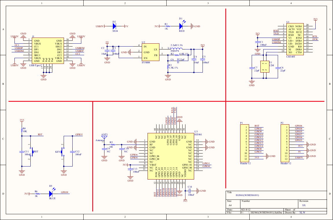
The picture above is the schematic of this board.
Compare the schematic above in normal and in JTAG mode.
In normal mode, Hi3861 pin IO4 is serial port input RXD, and connected to CH340T pin 3 TXD, serial port output.
When pin IO8 JTAG_ENABLE is pulled high, pins IO4..IO8 are used in JTAG mode. In JTAG mode, Hi3861 pin IO4 is JTAG_TMS output. This means there is a conflict: two output pins - Hi3861 pin IO4 and CH340T pin 3 - are connected together.
A possible solution is adding a resistor:
 |
 |
|---|---|
| before | after |
This way when the usb serial port is idle, CH340T pin 3 is high and R7 acts like a 4.7k pull-up resistor, which is what signal JTAG_TMS requires. Tested with JLINK and FT2232HL.
- reference design and documentation
- Tiny-Hi3861. Original on gitee
- genkipi
Modules with in-built pcb antenna are probably easiest to use in your own designs.
- Hi3861V100 product page
- Hi3881 hiburn for linux
- open source hiburn for Hi3861
- Hi3861 on aliexpress
- Installing Liteos on Hi3861 (in Chinese)
- Zephyr RTOS for Hi3861.
- FT2232HL schematic and shop.
xingrz provided the sections about booting, building LiteOS, Zephyr and flashing with the hiburn protocol.
This document may contain errors. If you find errors in this document, please open an issue or a pull request. If this page saved you some time, maybe you want to buy me a cup of tea. Thank you.
