A single-shot camera-projector calibration method that deals with imperfect planarity of the calibration target.
Highlights:
- The proposed method performs camera-projector pair calibration with only a single-shot, making it practically convenient in many applications. It can provide flexible and accurate results even when the board is handheld.
- A bundle adjustment (BA) algorithm is developed to jointly optimize the estimated camera/projector models and feature points in model space.
- Unlike many existing methods, to calibrate the system, we apply points from a Structured Light (SL) pattern rather than from a checkerboard. This strategy boosts not only the number of feature points but also their spatial distribution, and hence improves calibration robustness.
For more info please refer to our paper.
- MATLAB 2017b
- mexOpenCV v3.3.0
- Run
calibrate.mto generate experiment results of the proposed method. - Run
compareCalibrations.mto generate comparison results with real data. The proposed method, a generalized global homography-based method, the proposed w/o bundle adjustment and Moreno & Taubin method are compared. - Run
simulateCalib.mto generate comparison results with synthetic data .

To apply the proposed method to your data, please follow these steps:
- Print a checkerboard pattern and glue it to a white board. Make sure the checkerboard pattern is at the center of the white board and its width/height is around 1/3 of the white board's width/height.
- Place the white board (with checkerboard glued to it) in both camera and projector's FOV.
- Create a folder under directory data to save the images in the following steps. E.g., refer to calibration-11-13-17.
- Generate a structured light pattern and save the pattern image if you have never generated one by:
where
im = ImgProc.genStructuredLight(prjW, prjH);
imwrite(im,'pattern.png');
prjWandprjHis your projector's resolution width and height in pixel. - Capture an image of the white board with the camera and save it as
lightGrid[i].png, whereiis the ith position, e.g.,lightGrid01.pngis the first position. - Display the pattern image in full screen mode on your projector and capture an image. and save it as
colorGrid[i].png, whereiis the ith position, e.g.,colorGrid01.pngis the first position. Make sure the white board is not moved between steps 5 and 6. Note: please place the white board so that the superimposed color grid cell is at least 5 pixels wide in camera's view. - Change the position and orientation of the white board and repeat steps 5 to 7 at least three times.
- Once sufficient positions are captured, create a file named
calib-info.ymland type your camera-projector pair configurations, an example file is given as follows:%YAML:1.0 # Camera image width and height camW: 640 camH: 480 # Projector image width and height prjW: 800 prjH: 600 # Number of squares on checkerboard [x y] format # Note: Number of inner corners is (x-1)*(y-1) boardSize: [12, 15] # Size of checkerboard squares in mm sqSize: 17.1979 # Sets (position indices) to use for calibration sets: [1,2,3,4,5,6,7]
- Edit
dataRootanddataNameincalibrate.mto point to the root of data folder and the folder you just created, then runcalibrate.mto calibrate the camera-projector pair.
-
Reprojection error:
Method Camera Projector Stereo Moreno & Taubin 0.12356 1.5949 1.1311 Global homography 0.12356 5.7868 4.0928 Proposed w/o BA 0.41692 0.71052 0.58252 Proposed 0.34976 0.63517 0.51272 -
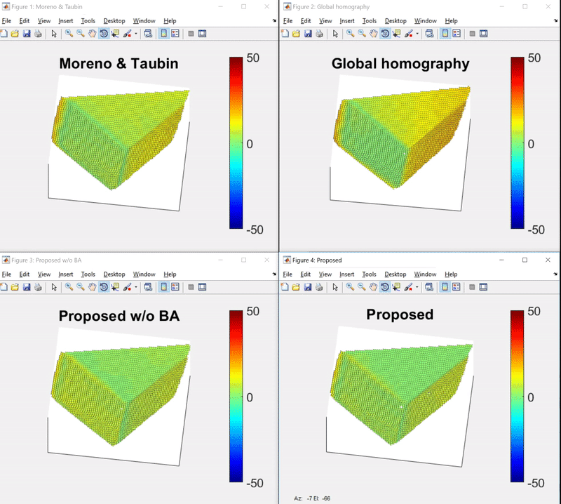
3D alignment error:
After we calibrate the camera-projector pair, we reconstruct a point cloud using 2D structured light point pairs and calibration data. To calculate reconstruction accuracy, we also capture the ground truth point cloud using an Intel RealSense F200 RGBD camera. The point cloud 3D alignment error (Euclidean distance) between the reconstructed point cloud and the ground truth point cloud are given by:
Method Min Max Mean Median Std. Moreno & Taubin 0.088551 55.194 8.4722 7.0756 5.9264 Global homography 0.016244 73.173 11.877 11.94 9.9919 Proposed w/o BA 0.046634 48.834 6.7798 6.8835 4.1002 Proposed 0.057853 50.807 5.5959 4.5881 4.7023 The per-point 3D alignment error can be viewed in pseudocolor:

The project folder is organized as follows:
├─+Calibration                  calibration package directory
├─+ImgProc                      image processing package directory
├─+Reconstruct                  3d reconstruction package directory
├─data                          directory for data
│  ├─calibration-11-13-17       directory for real data, contains checkerboard/structured light images and RealSense reconstructed ply files.
│  │  ├─matlabCorners           extracted checkerboard corners by MATLAB's detectCheckerboardPoints and warped corners by the global homography
│  │  ├─MT                      warped checkerboard points and reconstruction point pairs by Moreno & Taubin's software
│  │  └─results                 calibration results generated by the four methods mention in the paper with real data
│  └─simulation                 directory for simulation (synthetic) data
│      └─results                calibration results generated by the four methods mention in the paper with synthetic data
├─doc                           directory for documentation
└─README.md                     this file
Please cite these papers in your publications if it helps your research:
@inproceedings{huang2018a,
    author = "Huang, Bingyao and Ozdemir, Samed and Wei, Ying and Liao, Chunyuan and Ling, Haibin",
    title = "A Single-shot-per-pose Camera-Projector Calibration System For Imperfect Planar Targets",
    year = "2018",
    booktitle = "Adjunct Proceedings of the IEEE International Symposium for Mixed and Augmented Reality 2018 (To appear)"
}
This software is freely available for non-profit non-commercial use, and may be redistributed under the conditions in license.