
This is the final project for the Udacity Self-Driving Car Engineer Nanodegree. In this project, our team created several ROS nodes to implement core functionality of an autonomous vehicle. For more information about the project, see the project introduction here.

The members of team MunixX:
| Name | Slack handle | GitHub account | Udacity Email |
|---|---|---|---|
| Clemens Habedank (team lead) | @clemens | CleWiDank | clemens.w.habedank@gmail.com |
| Justin Lee | @justinlee | justinlee007 | justin.lee007@gmail.com |
| Aaron Piper | @apiper0770 | apiper0770 | apiper0770@gmail.com |
| Qiong Gui | @guiq | guiqiong | guiqcn@gmail.com |
| Tan Wang | @timn9408 | dayuwater | timmy940408@hotmail.com |
Please use one of the two installation options, either native or docker installation.
-
Be sure that your workstation is running Ubuntu 16.04 Xenial Xerus or Ubuntu 14.04 Trusty Tahir. Ubuntu downloads can be found here.
-
If using a Virtual Machine to install Ubuntu, use the following configuration as minimum:
- 2 CPU
- 2 GB system memory
- 25 GB of free hard drive space
The Udacity provided virtual machine has ROS and Dataspeed DBW already installed, so you can skip the next two steps if you are using this.
-
Follow these instructions to install ROS
- ROS Kinetic if you have Ubuntu 16.04.
- ROS Indigo if you have Ubuntu 14.04.
-
- Use this option to install the SDK on a workstation that already has ROS installed: One Line SDK Install (binary)
-
Download the Udacity Simulator.
Build the docker container
docker build . -t capstoneRun the docker file
docker run -p 4567:4567 -v $PWD:/capstone -v /tmp/log:/root/.ros/ --rm -it capstoneTo set up port forwarding, please refer to the instructions from term 2
- Clone the project repository
git clone https://github.com/udacity/CarND-Capstone.git- Install python dependencies
cd CarND-Capstone
pip install -r requirements.txt- Make and run styx
cd ros
catkin_make
source devel/setup.sh
roslaunch launch/styx.launch- Run the simulator
- Download training bag that was recorded on the Udacity self-driving car.
- Unzip the file
unzip traffic_light_bag_file.zip- Play the bag file
rosbag play -l traffic_light_bag_file/traffic_light_training.bag- Launch your project in site mode
cd CarND-Capstone/ros
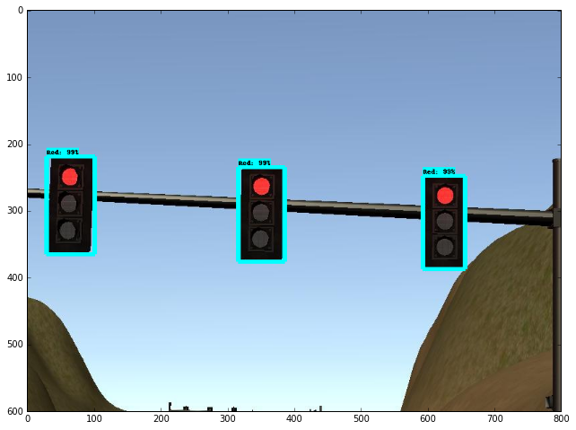
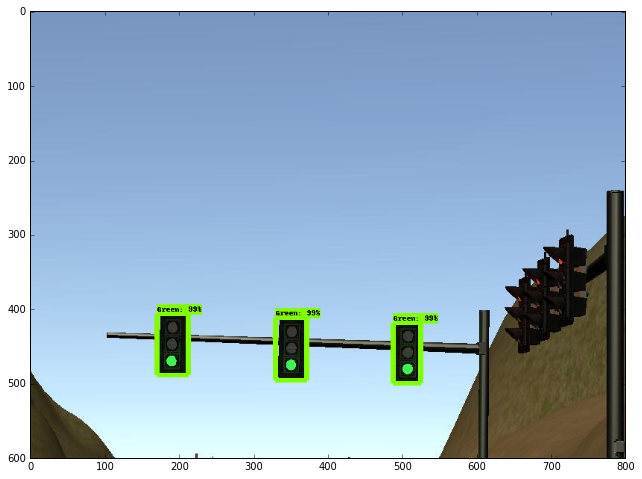
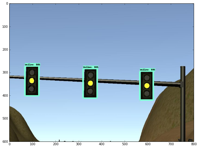
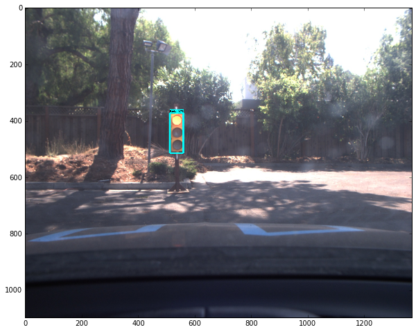
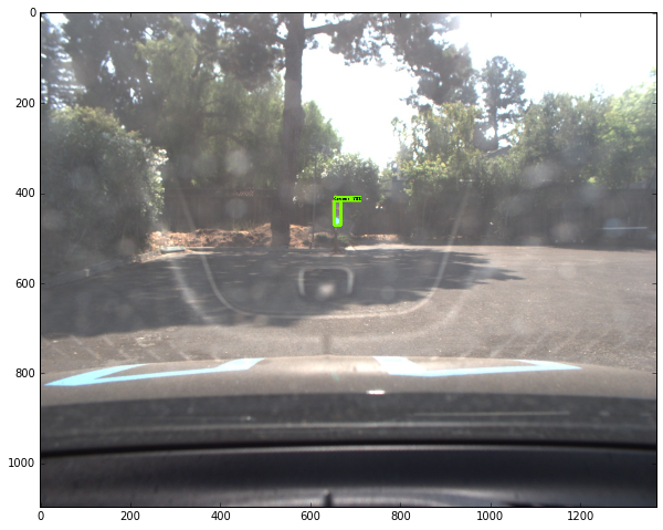
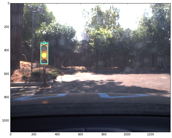
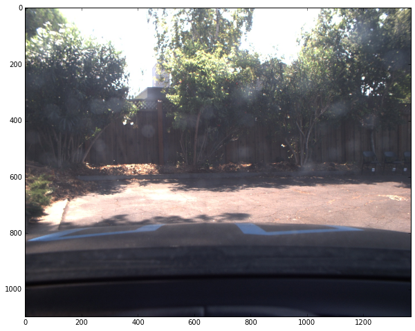
roslaunch launch/site.launch- Confirm that traffic light detection works on real life images
Carla is the custom Lincoln MKZ that Udacity has converted into a self-driving car. It's self-driving system is broken down into four major sub-systems: Sensors, Perception, Planning and Control

Includes everything needed to understand its surroundings and location including cameras, lidar, GPS, radar, and IMU
Abstracts sensor inputs into object detection and localization
- Includes software pipelines for vehicle detection, traffic light detection, obstacle detection, etc
- Techniques in image manipulation include Histogram of Oriented Gradients (HOG) feature extraction, color transforms, spacial binning
- Methods of classification include sliding-window or sub-sampling along with heat maps and bounding boxes for recurring detections
- Answers the question: “Where is our car in a given map with an accuracy of 10cm or less?”
- Based on the notion that GPS is not accurate enough
- Onboard sensors are used to estimate transformation between measurements and a given map
Path planning is broken down into for sub-components: route planning, prediction, behavioral planning, and trajectory planning
The route planning component is responsible for high-level decisions about the path of the vehicle between two points on a map; for example which roads, highways, or freeways to take. This component is similar to the route planning feature found on many smartphones or modern car navigation systems.
The prediction component estimates what actions other objects might take in the future. For example, if another vehicle were identified, the prediction component would estimate its future trajectory.
The behavioral planning component determines what behavior the vehicle should exhibit at any point in time. For example stopping at a traffic light or intersection, changing lanes, accelerating, or making a left turn onto a new street are all maneuvers that may be issued by this component.
Based on the desired immediate behavior, the trajectory planning component will determine which trajectory is best for executing this behavior.
The control component takes trajectory outputs and processes them with a controller algorithm like PID or MPC to adjust the control inputs for smooth operation of the vehicle.
The ROS Architecture consists of different nodes (written in Python or C++) that communicate with each other via ROS messages. The nodes and their communication with each other are depicted in the picture below. The ovally outlined text boxes inside rectangular boxes represent the ROS nodes while the simple rectangular boxes represent the topics that are subscribed or published to. The direction of the arrows clarifies the respective flow of communication.

The most central point in the rqt-graph is the styx_server that links the simulator and ROS by providing information about the car's state and surroundings (car's current position, velocity and images of the front camera) and receiving control input (steering, braking, throttle). The other nodes can be associated with the three central tasks Perception, Planning and Control.
The images get processed within the traffic light classifier by a trained neural network in order to detect traffic lights. The percepted state of a potentially upcoming traffic light is passed to the traffic light detector as well as the car's current pose and a set of base waypoints coming from the waypoint loader. With this frequently incoming information the traffic light detector is able to publish a waypoint close to the next traffic light where the car should stop in case the light is red.
With the subscribed information of the traffic light detector and the the subscriptions to base waypoints, the waypoint updater node is able to plan acceleration / deceleration and publish it to the waypoint follower node. This node publishes to the DBW (Drive by wire) node that satisfies the task of steering the car autonomously. It also takes as input the car's current velocity (coming directly from the car / simulator) and outputs steering, braking and throttle commands.

In this paragraph it will be talked about the node design of those nodes that are built within this project. Those are the waypoint updater(waypoint_updater.py), the traffic light detector (tl_detector.py) and the drive by wire node (dbw_node.py).
The waypoint updater node takes a central role in the planning task because it determines which waypoints the car should follow. The node is structured into different parts: First an import-part, where some python libraries and some message formats are imported. This is followed by the initialization of some constants that are not intended to be changed, e.g. how many waypoints are published and at what rate the publications occur. After this part, the class WaypointUpdater is introduced. The WaypointUpdater is structured into different functions. The first function is the init-function defining the attributes of the class and determining which topics the class subscribes to and which ones it publishes on. The following functions are either general methods or callback functions that are invoked repeatedly by the subscribers in the init-function. Repeatedly called are the base waypoints (output of waypoint loader), the car's pose (simulator / car) and the traffic waypoint (output of tl_detector). The most important general method is the decelerate_waypoints-function which incorporates a square-root shaped deceleration towards a predetermined stopline location in case of red traffic lights. At the end of the node there is the main function that runs the node and logs an error in case ROS is interrupted for any reason.
The structure of the traffic light detector is identical to the Waypoint Updater in the sense that there is an import/initialization section followed by a class with attributes and functions. Finally TL detection subroutine utilizes its main function to compile the code. The init-function of the TLDetector class includes the subscriptions to the current position base waypoints, the given traffic light array with the ground-truth coordinates of the traffic lights, along with the identified color of the traffic light. The color of the traffic light is the output of the traffic light classifier, a neural network that is explained in more detail in the next paragraph. The topic image_color gets updated by the callback image_cb, which itself calls via the process_traffic_lights() function, who in turn utilizes the function get_light_state() that receives the traffic light classification. Eventually, the waypoint to stop at for any upcoming identified red traffic light is published in this subroutine.
The third node written by us is the dbw_node which is responsible for steering the car. It subscribes to a twist controller which outputs throttle, brake and steering values with the help of a PID-controller and Lowpass filter. The dbw node directly publishes throttle, brake and steering commands for the car/simulator, in case dbw_enabled is set to true.
The traffic light classification model is based on the pre-trained on the COCO dataset model "faster_rcnn_resnet101_coco" from Tensorflow detection model zoo. Using the Tensorflow Object Detection API, the simulator data model and real data model were trained.
The models are available in the ros/src/tl_detector/light_classification/train_model directory or here.
Step-by-step Tensorflow Object Detection API tutorial was a good guide of using the Tensorflow object detection API for traffic light classification.
The simulator dataset was from here, and the real dataset was from here.
The classification output has four categories: Red, Green, Yellow and off. To simplify, the final output will be Red or Non-Red, that is only the Red will be classified as TrafficLight.RED, and the other cases will be classified as TrafficLight.GREEN.
After getting the program working, the walkthrough videos were then posted to the Udacity project page. As they had a much more elegant approach to implementing the nodes, there was a re-write effort to conform to the walkthrough approach rather than the teams originally conceived method.
Here is a sample video of the test track running.
One of the hardest tasks for this project was getting the environment setup. Apple products are essentially not supported and any computer without a very powerful GPU is incapable of running the network while the simulator is simulatenously running.
Our team was also puzzled by how the vehicle should interact and maneuver within the test lot in order to complete the project. The test track for our team is straight-forward in execution as there are standard rules of the road that must be followed to successfully traverse the track. There are also, generally speaking, standardized maneuvers to perform on the road that lead to easy vehicle behavior trajectories on the test track. On the other hand the test lot is troublesome and quirky because of the lack of standarized rules of road, and a lack of standardized maneuvers to perform within the test lot.
Overall, this was a challenging and rewarding project, both technically and socially. The use of ROS within a small team, each member of which was located in different part of the world, presented unique opportunities for learning and growth.