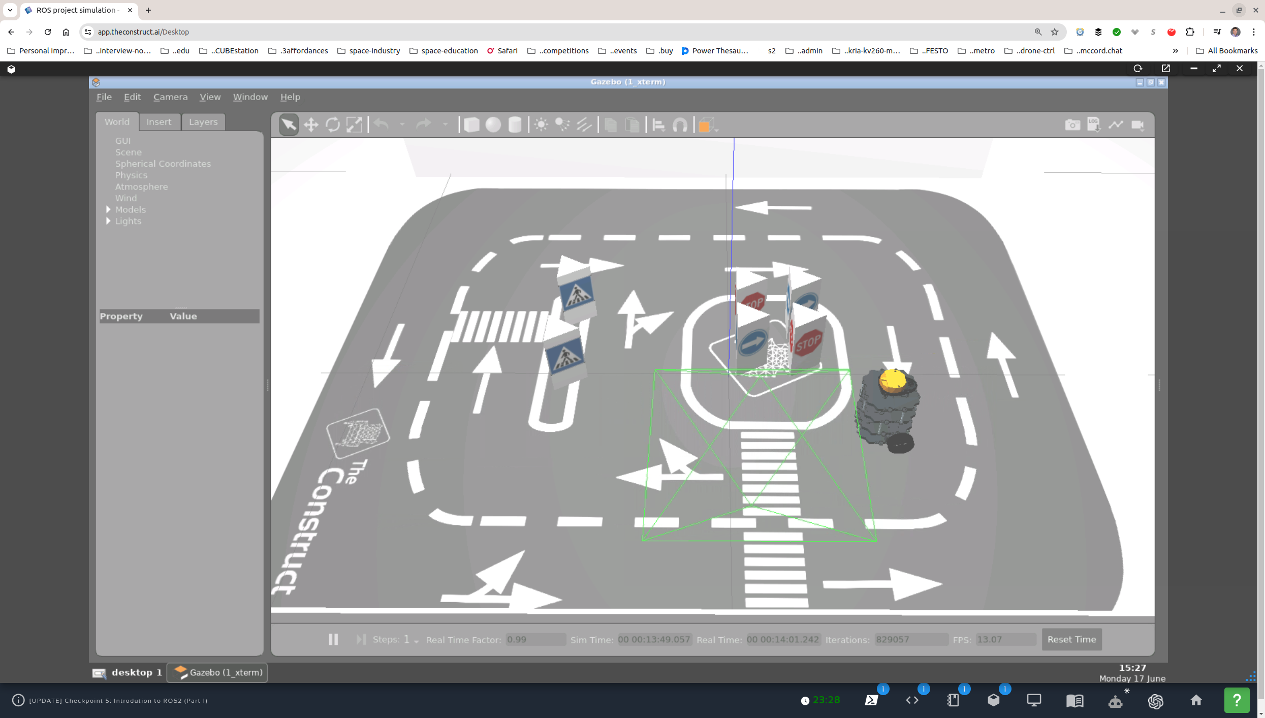
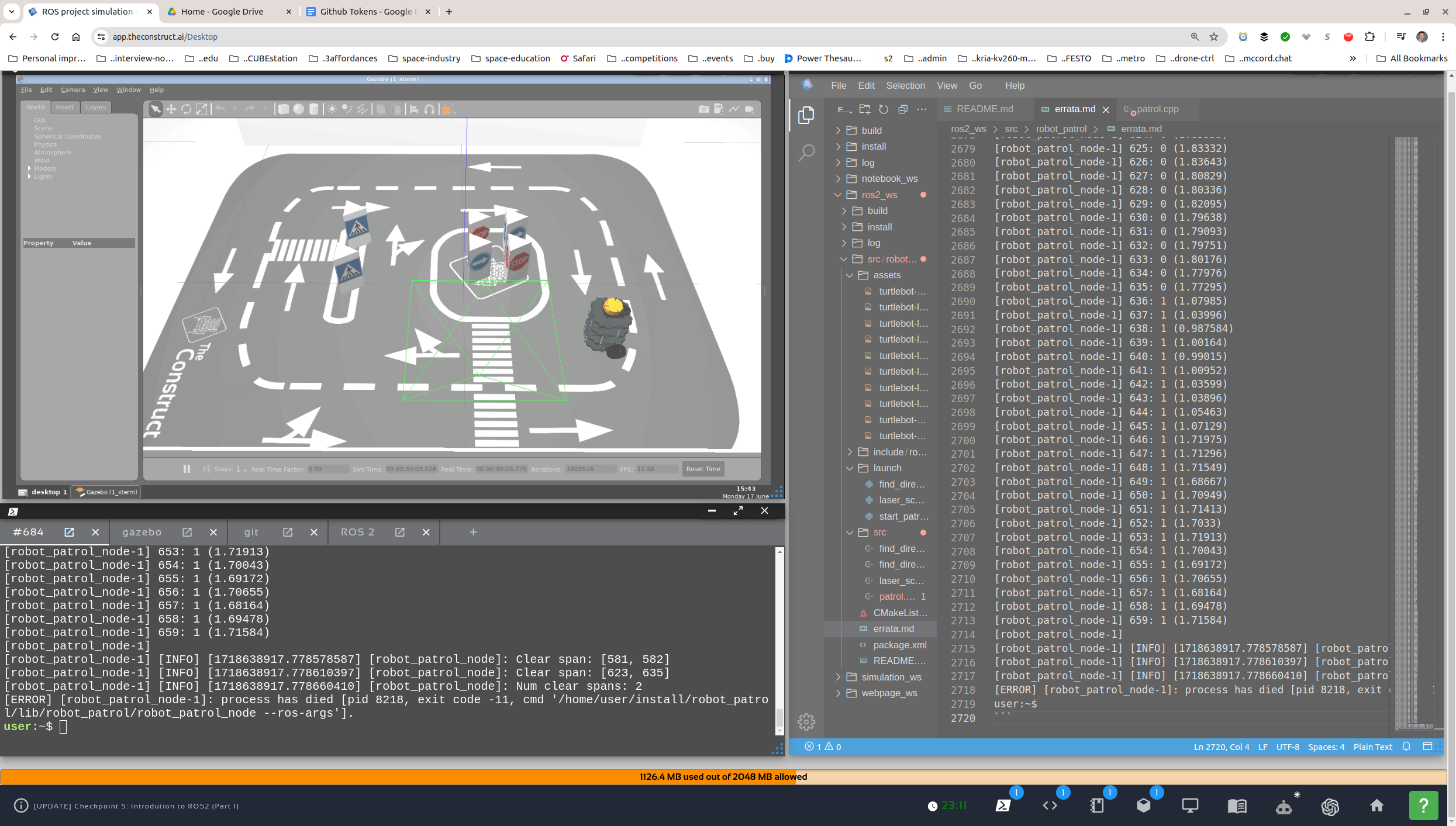
A turtlebot3 patrolling the simulated and real robot pen/polygon. Patrolling means constantly moving and avoiding obstacles.
- Checkpoint 5 (ROS 2 Topics)
- Running:
cd ~/ros2_ws/src git clone https://github.com/ivogeorg/robot_patrol.git git checkout checkpoint-5 colcon build --packages-select robot_patrol ros2 launch turtlebot3_gazebo main_turtlebot3_lab.launch.xml ros2 launch robot_patrol start_patrolling.launch.py- Controlling the log verbosity level:
- In source code (C++):
#include <rclcpp/rclcpp.hpp>

int main(int argc, char ** argv)
{
rclcpp::init(argc, argv);
auto node = std::make_shared<rclcpp::Node>("robot_patrol");

auto logger = rclcpp::get_logger("robot_patrol_node");

// Set the log level to DEBUG
if (rcutils_logging_set_logger_level(
        logger.get_name(), RCUTILS_LOG_SEVERITY_DEBUG) != RCUTILS_RET_OK) {
    // Handle the error (e.g., print an error message or throw an exception)
    RCLCPP_ERROR(logger, "Failed to set logger level for robot_patrol_node.");
} else {
    RCLCPP_INFO(logger, "Successfully set logger level for robot_patrol_node.");
}

rclcpp::spin(node);
rclcpp::shutdown();
return 0;
}
- In source code (C++):
- Controlling the log verbosity level:
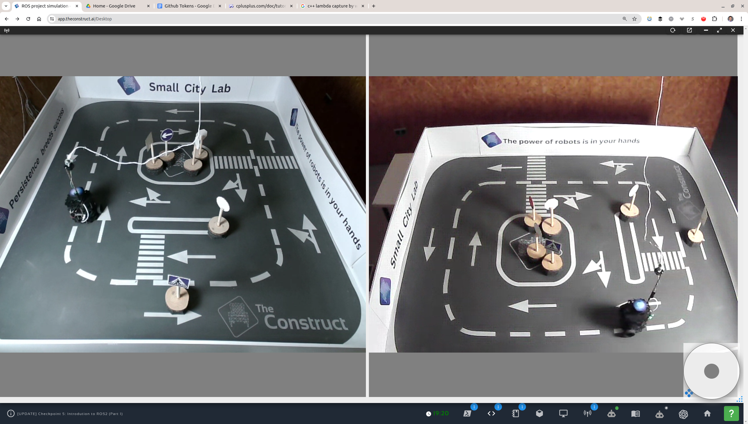
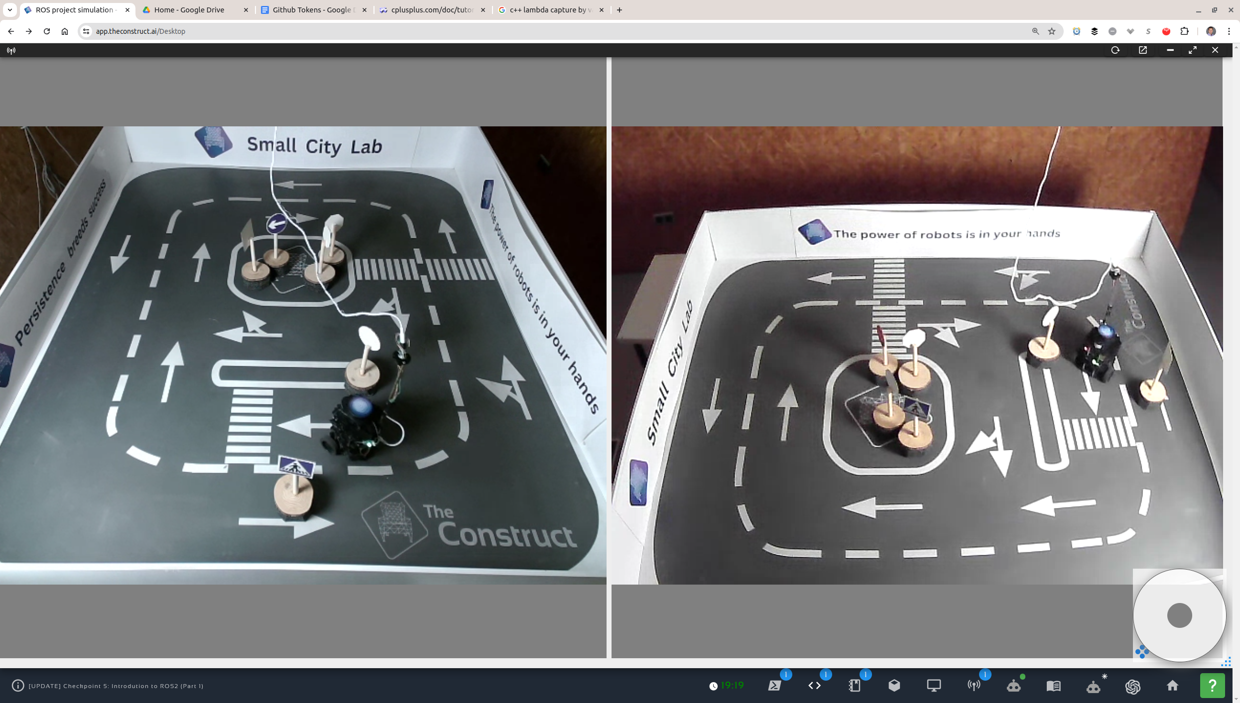
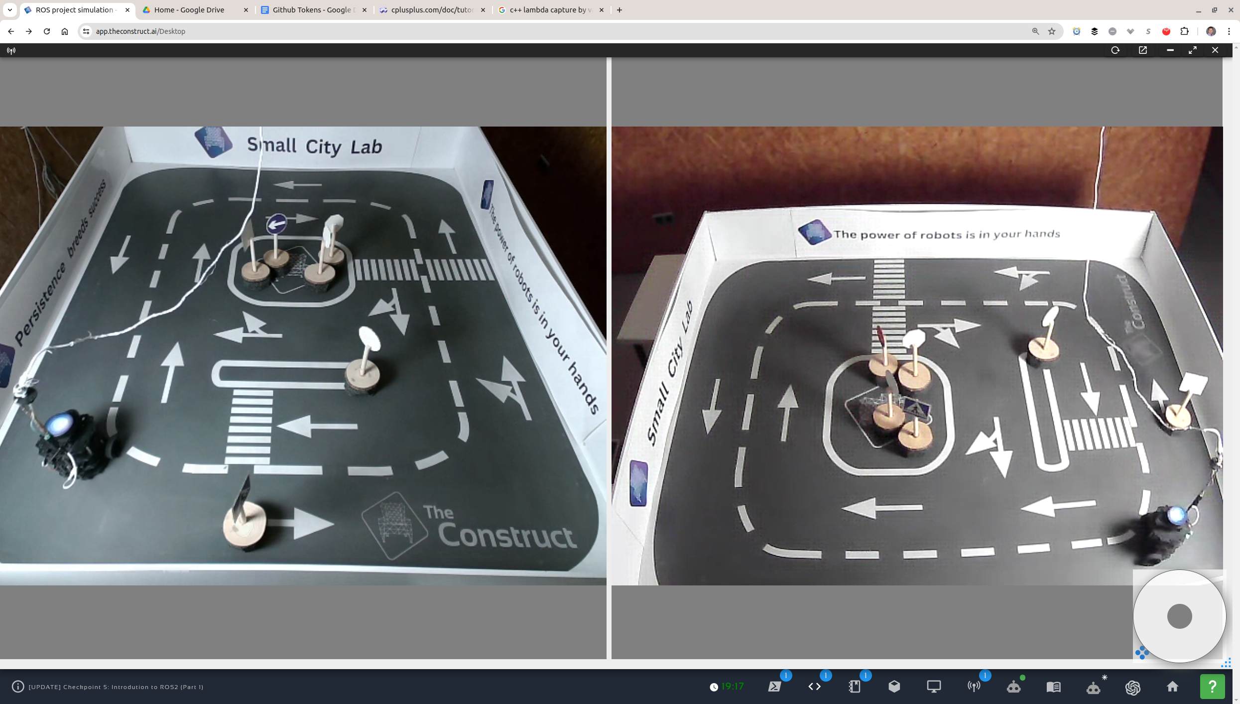
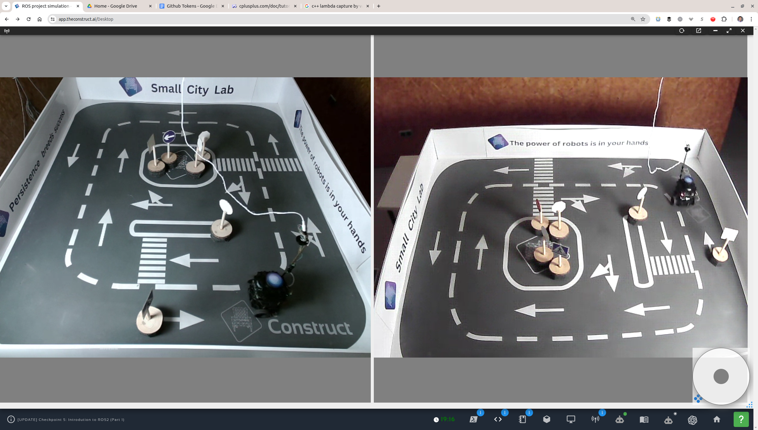
- Screenshots
Turtlebot 3 Lab Live 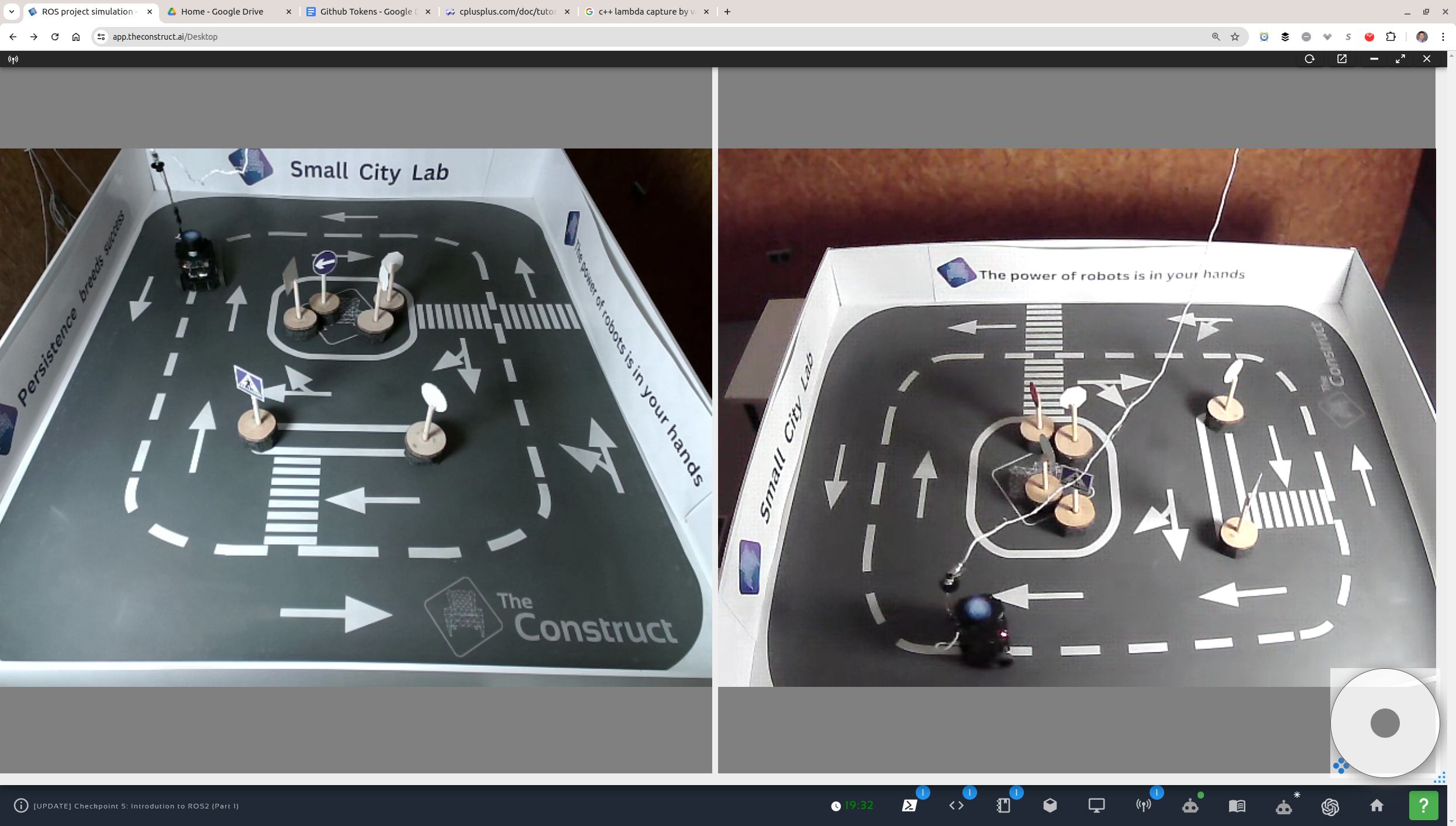
- Implementation notes
- The program uses the first scan message to initialize its nav parameters.
- The robot looks for obstacles in front in a 30-deg arc, centered at the front direction.
- Four different nav algorithms were implemented:
- The simple "wall follower" from the quiz code. This did not meet the requirements for rotating for looking for new direction.
find_direction_heuristic, a heuristic-based safety-criterion algorithm for filtering candidate directions. Directions are sorted on the basis of how close the neiboring directions' directions form an inverse quadratic function, and upon equality, on the size of the range.find_direction_foreground_buffers, a buffer-based robot-clearance algorithm for filtering candidate directions. Forward obstacles are identified against the background of the walls. Clear spans are identified in a 360-deg circular array and safety buffer angles are used to pad each clear span at each end. Clear spans are then filtered by their resulting clearance and the remaining ones are sorted by range size. This last algorithm was motivated primarily by the existence of traffic-sign base obstacles that are both below the LIDAR scan plane and are wider than the widest traffic sign place, creating a hazard of catching a robot wheel on a traffic-sign base.find_direction_arc_sums, an angle arc-based heuristic-clearance algorithm, akin to (2) but simpler. Currently running. Arc ranges are summed and sorted by two sums, one arc and three arcs with the former in the middle. The sorting is by the 3-arc sum first and then by the middle arc. It works fine in the simulator, but still has problems identifying the traffic-sign obstacles in the lab, especially if it does not approach them head on. More robust toinfvalues in the lab scanner.
- All (2),(3), and (4) can be boosted to an extended range for direction search. This is done automatically upon encountering anomalous situations, like being too close to an obstacle or oscillating between two directions without moving.
- If the robot is too close to an obstacle, in particular closer than
range_min, it is able to recognize the situation and back up to farther thanOBSTACLE_FWD_PROXIMITY(0.35 m). - Despite algorithm (3), the robot had a problem seeing one of the signs and pushed it out toward the wall. It did identify all other obstacles and stayed away from them. It also successfully identified oscillation between two directions in the 180-deg span, both with obstacles, and extricated itself by backing up and extending the direction search to the full 360-deg circular array of the scan data.
- Running:
- Checkpoint 6 - Part 1 (ROS 2 Services)
- Running
- Direction service test (in 3 terminal windows):
- Gazebo simulator
source ~/simulation_ws/install/setup.bash ros2 launch turtlebot3_gazebo main_turtlebot3_lab.launch.xml /cmd_velfor moving in circlesros2 topic pub --once /cmd_vel geometry_msgs/msg/Twist "{linear: {x: 0.05, y: 0.0, z: 0.0}, angular: {x: 0.0, y: 0.0, z: 0.3}}"- Direction service
cd ~/ros2_ws source install/setup.bash ros2 launch robot_patrol start_direction_service.launch.py - Service testing
cd ~/ros2_ws
source install/setup.bash
ros2 launch robot_patrol start_test_service.launch.py
- Gazebo simulator
- Patrol with service (Gazebo simulator omitted):
cd ~/ros2_ws
source install/setup.bash
ros2 launch robot_patrol main.launch.py
- Direction service test (in 3 terminal windows):
- Screenshots

- Implementation notes
- For custom messages that are (to be) generated in the same package where they will be used in source code, the following need to be added to the
CMakeLists.txtfile:- Explicit DEPENDENCIES line for the base message(s) used to construct the custom interface (in this case
sensor_msgsforsensor_msgs/LaserScan):rosidl_generate_interfaces(${PROJECT_NAME} "srv/GetDirection.srv" DEPENDENCIES sensor_msgs ) - To link the generated (type support) library to a package executable (where it is used):
add_executable(direction_service_node src/direction_service.cpp)
ament_target_dependencies(direction_service_node rclcpp)

# To link to interfaces defined and generated in the same package:

# Get the typesupport target name
rosidl_get_typesupport_target(typesupport_target ${PROJECT_NAME} "rosidl_typesupport_cpp")

# Link against the generated interface library
# NOTE: No keywords (PRIVATE, PUBLIC) or all keywords (can't mix)
target_link_libraries(direction_service_node ${typesupport_target})
- Explicit DEPENDENCIES line for the base message(s) used to construct the custom interface (in this case
- The vanilla algorithm with fixed velocities depending on the direction service value is not robust. For that reason, the following additions were made:
- Navigational awareness was added to the robot in the form of distance to obstacles in front of it.
- The direction service response is used as a basis and a guideline. On the basis of it, a sector is picked to look for the direction with the farthest range.
- A velocity control vector is used to adjust the linear and angular velocities depending on the proximity to obstacles in front. Details.
- For custom messages that are (to be) generated in the same package where they will be used in source code, the following need to be added to the
- There is a clear disparity between the dynamics of the simulator and that of the lab.
- For the same angular velocity values, the lab robot turns faster and therefore makes a larger arc.
- The angular velocities were tuned per environment, in
parametrize_laser_scanner, as this is the only sure criterion to tell the lab from the simulator. - In particular, the angular velicities were decreased by 0.5 for the lab from the values fine-tuned for the simulator, and also the obstacle detection distances for the lab were decreased by 1.0.
- Running
- Checkpoint 6 - Part 2 (ROS 2 Actions)
- Running (Gazebo omitted)
go_to_poseaction servercd ~/ros2_ws source install/setup.bash ros2 launch robot_patrol start_gotopos_action.launch.py- Send requests from a terminal
ros2 action send_goal -f /go_to_pos robot_control/action/GoToPose "goal_pos:
  x: 0.7
  y: 0.3
  theta: 90.0
"
- Screenshots
Robot at origin Robot at (0.7, 0.3) 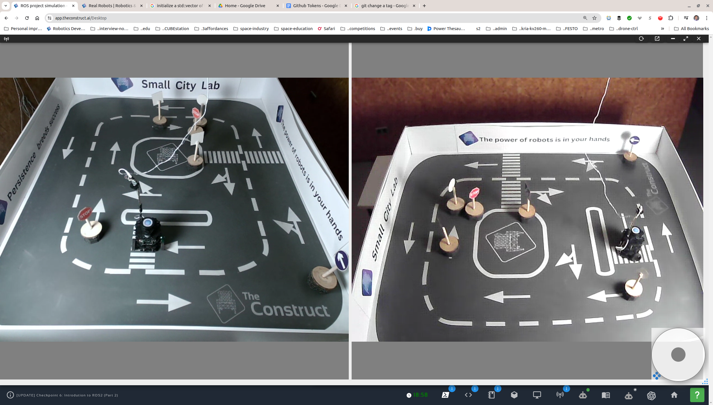
- Implementation notes
- The action server sends feedback twice a second.
- The
thetaparameter is in the world frame and is in degrees in both the request and the feedbacks. - The goal is achieved in three steps:
- Rotate toward the goal.
- Go forward the distance to the goal.
- Rotate to
thetain the world frame.
- Inaccuracies in the rotation cause the robot to go to an approximation to the goal coordinates. Due to these inaccuracies, the second step is tracking distance rather than coordinates. If there is even a small rotation error (by 1-2 degrees), the robot's coordinate-based condition would never trigger to stop it.
- Running (Gazebo omitted)


[laser_scan_subscriber_node]: angle_min = -3.141600
[laser_scan_subscriber_node]: angle_max = 3.141600
[laser_scan_subscriber_node]: angle_increment = 0.009534
[laser_scan_subscriber_node]: range_min = 0.120000
[laser_scan_subscriber_node]: range_max = 30.000000
[laser_scan_subscriber_node]: ranges.size() = 660

[laser_scan_subscriber_node]: ranges[0] = 1.610980
[laser_scan_subscriber_node]: ranges[164] = 1.600037
[laser_scan_subscriber_node]: ranges[329] = 0.226959
[laser_scan_subscriber_node]: ranges[493] = 0.470259
[laser_scan_subscriber_node]: ranges[659] = 1.572943
    /**
        This shows that the turtlebot3 laser scan is parameterized thus:
                 329
              _________
            |||   ^   |||
            |||  fwd  |||
        493   |l     r|   164
              |       |
              |___b___|
                  0 (659)
        These are the indices of the ranges array:
        329 - forward (also approximately 359)
        493 - left
          0 - backward
        164 - right
    */

- The current yaw of the robot is extracted from the odometry message:
yaw_ = yaw_from_quaternion( msg->pose.pose.orientation.x, msg->pose.pose.orientation.y, msg->pose.pose.orientation.z, msg->pose.pose.orientation.w);` - Using the formula, this works fine in the Gazebo simulator:
atan2(2.0f * (w * z + x * y), w * w + x * x - y * y - z * z); - The values are +/- pi radians, equivalent to +/- 180 degrees.
In short, angle zero being "forward along the x-axis" doesn't mean that index zero of the ranges vector coincides. It is actually diametrically opposite.
- In
tutrlebot3_burger.urdf, there is no rotation in the joints betweenbase_footprintandbase_link, nor betweenbase_linkandscan_base. - In
empty_world.launch.py, the robot appears in default pose with the forward direction along the x-axis. The LIDAR is therefore aligned the same way.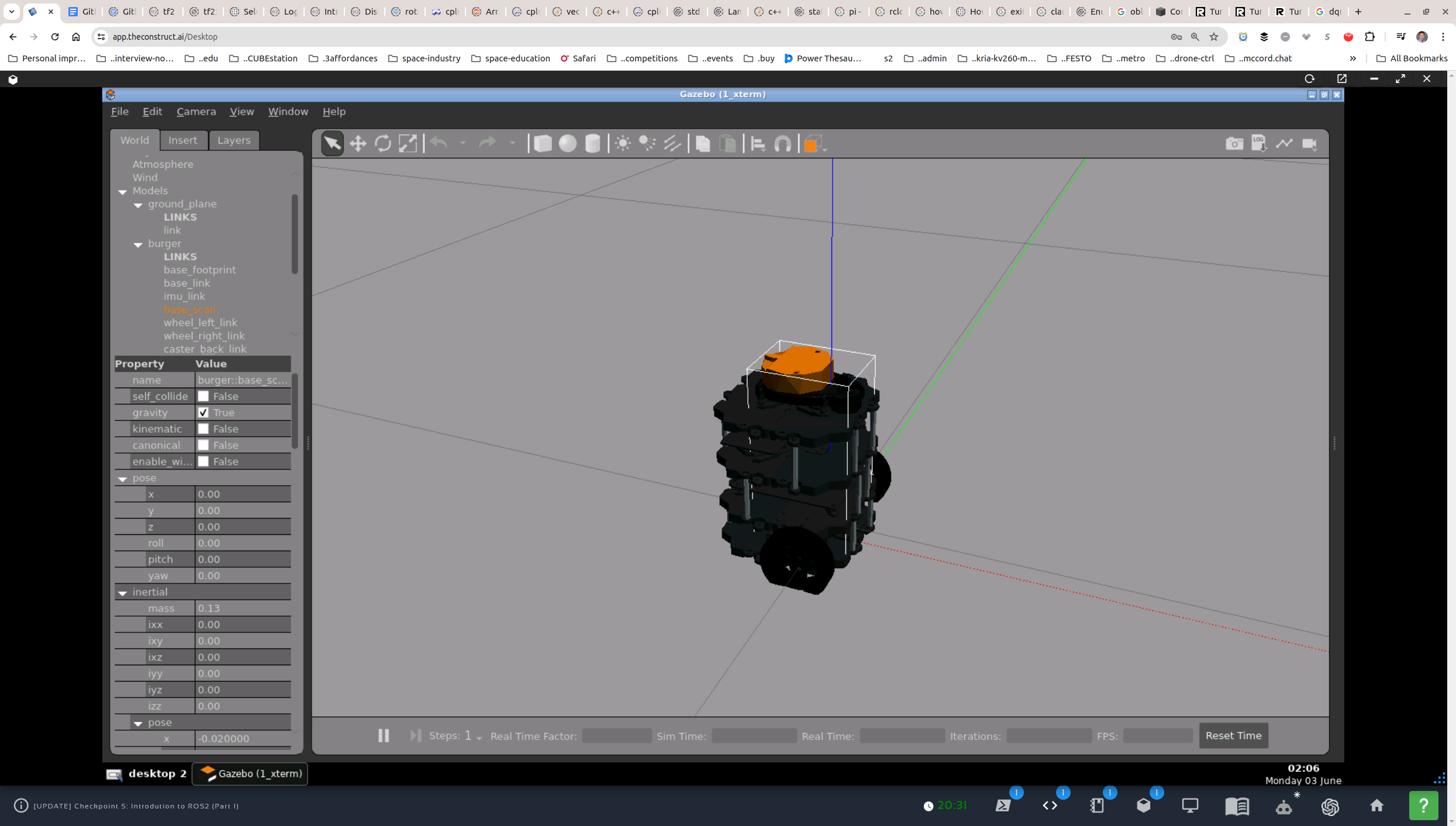
- In the simulator, I positioned the robot in such a way that it was unambiguous which index was 0, and it was the exact opposite of what
ros2 interface show sensor_msgs/msg/LaserScanstates (below). My index 0 is backward (not forward) along the x-axis.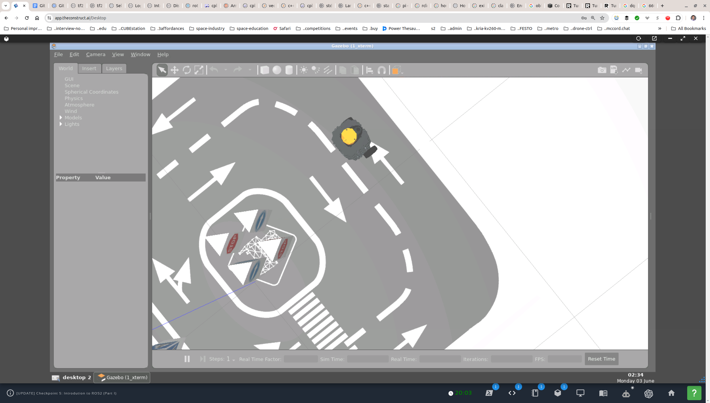 Readings:
angle_min = -3.141600
angle_max = 3.141600
angle_increment = 0.009534
range_min = 0.120000
range_max = 30.000000
ranges.size() = 660

ranges[0] = 0.498451
ranges[164] = 1.056713
ranges[329] = 0.195327
ranges[494] = 0.789187
ranges[659] = 0.485331
ros2 interface show sensor_msgs/msg/LaserScanreads:std_msgs/Header header # timestamp in the header is the acquisition time of builtin_interfaces/Time stamp int32 sec uint32 nanosec string frame_id # the first ray in the scan. # # in frame frame_id, angles are measured around # the positive Z axis (counterclockwise, if Z is up) # with zero angle being forward along the x axis float32 angle_min # start angle of the scan [rad] float32 angle_max # end angle of the scan [rad] float32 angle_increment # angular distance between measurements [rad] float32 time_increment # time between measurements [seconds] - if your scanner # is moving, this will be used in interpolating position # of 3d points float32 scan_time # time between scans [seconds] float32 range_min # minimum range value [m] float32 range_max # maximum range value [m] float32[] ranges # range data [m] # (Note: values < range_min or > range_max should be discarded) float32[] intensities # intensity data [device-specific units]. If your # device does not provide intensities, please leave # the array empty.


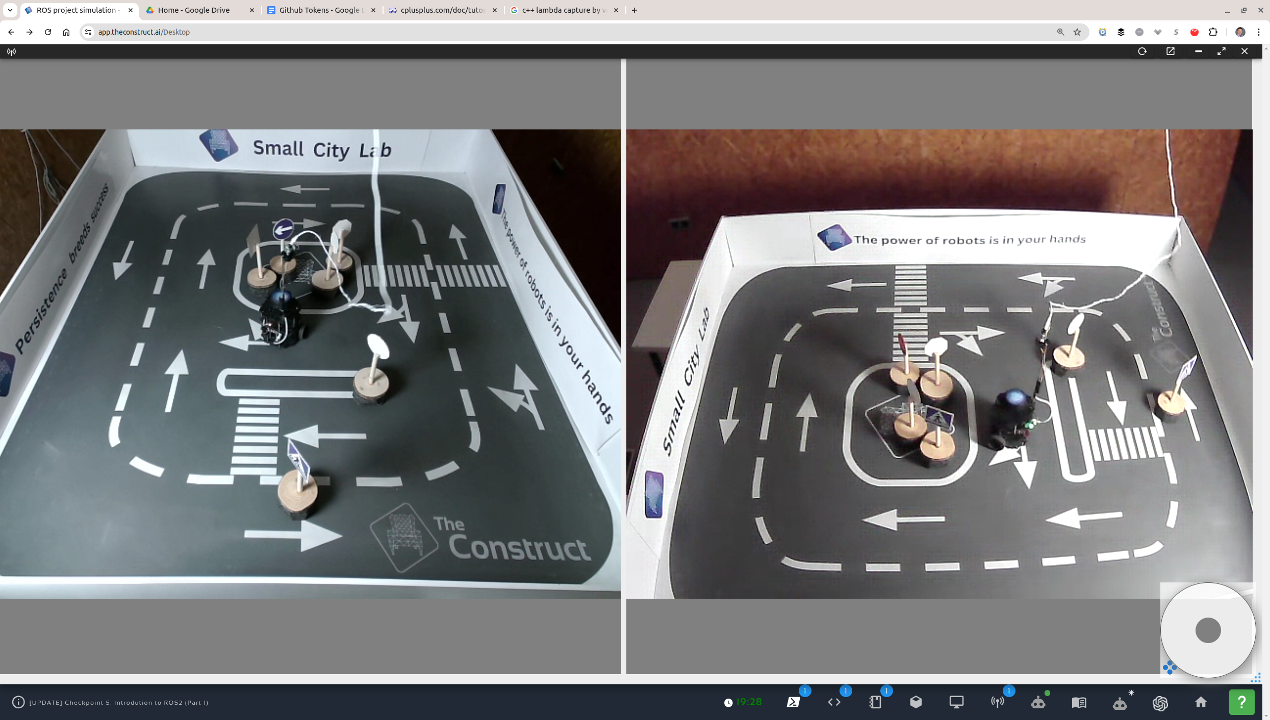
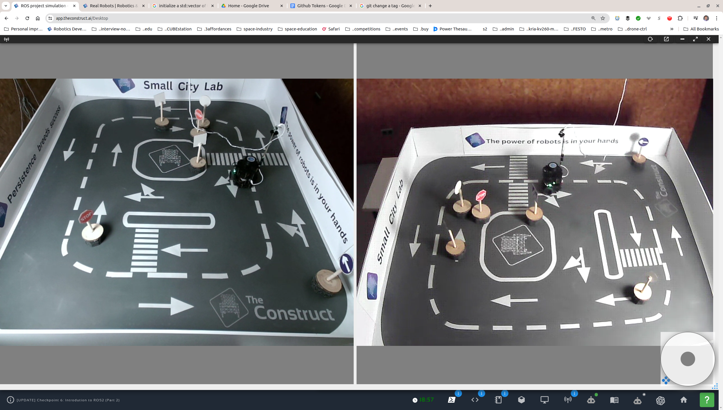
The actual TurtleBot3 lab.
-
The hardest spots for the robot, where it tens to either start oscillating or (if the oscillation is actually only in the code) get stuck, are:
- Corners.
- Corner-like spots with traffic-sign obstacles.
- Finding itself too close (around or under
min_range) to an obstacle.
-
Remediation measures:
- Direction safety (like convex-fitting) (default/fixed).
- Bias (optional):
- Larger angles.
- Larger ranges.
- Randomize (optional):
- Direction (left, right).
- Extend (optional):
- New direction span (from +/- pi to under +/- 2 * pi).
- Back up (move backward) (optional);
-
Detecting problematic cases:
- Oscillation: count calls to
find_safest_directionwith no significantx, ymovement. - Too close and stuck: count
infvalues in the range[FRONT_FROM, FRONT_TO]. - New directions too close to current orientation: within tolerance of current orientation.
- Oscillation: count calls to
-
SOSstate that would relax the requirements and allow the robot to extricate itself when it detects that it is stuck. Some of the parameters to relax:- Angle to look for new directions > +/- pi. Add
extended = falseparameter tofind_safest_direction. Watch for wraparound. May need to normalize at the edges. - Slow backward movement (
cmd_vel_msg_.linear.x = -0.05;) with close 360-degree monitoring of obstacles. - Note that if the robot is somehow stuck too close to an obstacle, it might be closes than
range_minand therefore showinfvalues!
- Angle to look for new directions > +/- pi. Add
-
(advanced) Add buffer space around obstacles to avoid the wheels catching the bases of the traffic signs. See lab camera views above.
- Measure arc-width of the detected obstacles.
- Calculate the if one of the wheels might catch the obstacle.
- Modify the direction of the robot to avoid the obstacle.
- Do this dynamically throughout as obstacle widths will vary depending on the (changing) orientation relative to the robot (point of view).
- This will require the dimensions of the robot.
-
Multithreading protection.
laser_scan_data_orlast_laser_scan_data_.
-
find_direction_buffers- In a circular array, find the first discontinuity, say at
[35, 36]. - Identify its type,
DROPorRISE. - Set
index_zeroto36. - In a circular array loop, mark the obstacles.
- Array of
size. - From
index_zeroto(index_zero - 1 + size) % size. obstacle_markeristrue(or1).- If first discontinuity was
DROP, an obstacle starts at36, so start marking with1, else0. - Flip
obstacle_markerat every discontinuity.
- Array of
- In a circular array loop, identify the clear spans.
- Array of
size. - From
index_zeroto(index_zero - 1 + size) % size. - Identify
span_start_ixandspan_end_ix. Put in astd::pair? - Calculate width of clear span. Note: Circular array! Spans should be monolithic across the discontinuity
[size - 1, 0]. - Define
ROBOT_WIDTH_ANGLEandROBOT_HALF_WIDTH_ANGLEin radians (double). Define for a robot that is half ofSMALLER_DIMENSIONfrom an obstacle it wants to pass on the side and the obstacle is of radius half-robot width around the single detectable point on the axis. So,ROBOT_HALF_WIDTH_ANGLEis:obstacle robot ------- ------- | *..|||..* ||<-- b/n Klein starts is robot width (0.2) ----\-- | | | \ --|-- \ | \ |<------ smaller_dim (1.85) \ | \ | \|- Range to center of obstacle (left *) is
sqrt(robot_width*robot_width + half_smaller_dim*half_smaller_dim). Call itobstacle_ctr_range. ROBOT_WIDTH_ANGLEiscos(smaller_dim / obstacle_ctr_range).>>> angle_increment = 0.009534446522593498 >>> smaller_dim = 1.85 >>> robot_width = 0.2 >>> half_smaller_dim = smaller_dim / 2.0 >>> obstacle_ctr_range = math.sqrt(half_smaller_dim**2 + robot_width**2) >>> robot_width_angle = math.acos (half_smaller_dim / obstacle_ctr_range) >>> buffer_span = robot_width_angle / angle_increment >>> buffer_span 22.333582665213278- Move this and downstream setup into a separate function or add to
parametrize_laser_scanner.
- Range to center of obstacle (left *) is
- Calculate
LEFT_BUFFERandRIGHT_BUFFERin number of indices (int) fromROBOT_WIDTH_ANGLE.LEFT_BUFFER = RIGHT_BUFFER = 22; - Apply
LEFT_BUFFERandRIGHT_BUFFERto the span (std::pair) and calculate new width. - Apply
leftandrightalloweable span, normal (+/- pi rad) orextended(+/- 2 * pi rad).- If standard (
extended = false), intersect spans withleft-right, and calculate new width. - If extended (
extended = true), do not modify further.
- If standard (
- If width is more than
2 * LEFT_BUFFER:- Find
largest_range, the largest range in the (buffered or buffer-reduced) index span. - Append
largest_rangeandlargest_range_indextostd::vector<std::pair<double, int>> clear_spans;.
- Find
- Array of
- Sort
clear_spansby range in descending order. - Set
direction_to the second element of the top/head entry of the sorted vector.
- In a circular array, find the first discontinuity, say at
- Setup
stuck_threshold_(x,y-space) ~0.10 CONSIDER!!!too_many_turns_threshold_~5
- Track
last_state_takes care of all the cases where state logic depends on the previous state, specifically inState::STOPPEDwhen arriving fromState::TURNINGandState::BACK_UP.turns_(after completing a turn)- set after completing a turn in
State::TURNING - unset in
State::STOPPEDwhen starting forward linear
- set after completing a turn in
- Report
is_oscillating_- set in
State::STOPPEDWhat is the purpose? CONSIDER!!! - unset ???
- set in
too_close_to_obstacle_- set in
State::STOPPED - unset ???
- set in
enum class State { STOPPED, FORWARD, FIND_NEW_DIR, TURNING, BACK_UP };
- STOPPED
0. check for anomalies
- check for oscillating, i.e. turning not moving away from an obstacle (i.e. still obstacle in front)
- check if too close in
std::tuple<bool, float>fromobstacle_in_range - if anomalies => BACK_UP, FIND_NEW_DIR (extended=true, bias=ANGLE)
- if no anomalies, no obstacle => FORWARD
- if no anomalies, yes obstacle => FIND_NEW_DIR (extended=false)
- if obstacle, just turned and 6 turns =>
is_oscillating_ = true;,BACK_UP - if no obstacle and
just_backed_up_=> setextended_range_ = true;andFIND_NEW_DIR
- FORWARD
- if obstacle => FIND_NEW_DIR (extended=false)
- FIND_NEW_DIR
- if
extended_range_, do extended - set
extended_range_ = false; - done => TURNING
- if
- TURNING
- done => STOPPED
++turns_;- set
just_turned_ = true;
- BACK_UP
- back up slowly until no obstacle in FRONT spread
- closely monitor obstacles in BACK
too_many_turns_threshold_should be even, so as to back up in a direction that is less likely to be problematic- set
just_backed_up_ = true;=> STOPPED
find_safest_directionbias angle or range (in tuple vector for "safety" sorting)enum class DirSafetyBias { ANGLE, RANGE };ANGLEfavors larger angles,RANGEfavors longer ranges. Bias applied after safety criterion!!!- new function parameter
dir_safety_bias = DirSafetyBias::ANGLE - defaulting on
DirSafetyBias::RANGEmight work better with safety criterion, withDirSafetyBias::ANGLEapplied to help getting unstuck.
direction biasenum class DirPref { RIGHT, LEFT, RIGHT_LEFT, NONE };NONEreturns the index of the safest dirv_indexed_averages[0],LEFT_RIGHTis based on the count of directions to the left and right.- new function parameter
dir_bias = DirPref::NONE
- deep review of the core "safety" criterion and strength of biases
oscillation- ESSENCE:
just_turned_and there is an obstacle (inSTOPPED) - count in
State::TURNINGcalls tofind_safest_direction - check the angle between the two directions CONSIDER!!!
- ESSENCE:
too close to obstacle (possibly underrange_min)- count the
infinobstacle_in_range - a std::tuple<bool, float> return value for
is_obstacleand the ratio ofinf(to all) - check in
State::STOPPEDorState::FORWARDCONSIDER!!! - set
too_close_to_obstacle_
- count the
anomalous states- one
State::SOS- pro: catch-all for anomalous situations, a unified strategy for extrication
- con: potentially too complex for pass-through
State::OSCILLATIONANDState::TOO_CLOSE- pro: easier for pass-through
- con: different strategies might be redunant and/or error-prone
State::BACK_UPis best, logic inState::STOPPED
- one
Buffer angle (indices) for obstacles under the LIDAR plane:- It's important to distinguish between walls (background) and signs (foreground). The idea is to add buffer angles on both sides of the foreground obstacles while leaving the background unchecked. Get ideas from the ros2-nav2 tutorial.
- Loop through
rangesarray and identify abrupt drops and jumps in distance. Going CCW from0toRANGES_SIZE, the first will be a drop and is the right edge, the second is going to be a jump and is the left edge, with the middle being the foreground obstacle. - Add buffer angle to each side, down the indices on the right or the right edge and up the indices to the left of the left edge. In a nested loop, this can be achieved by marking as obstacle the buffer-angle-corresponding indices on both sides of each originally identified point of a foreground obstacle, including the edges. The buffer added may depend on the distance, smaller for farther obstacles and larger for nearer obstacles.
- The resulting picture of obstacles represents the available ranges. Pick the middle of each span of available ranges as the direction candidate and sort first by width then by distance in descending order.
- Pick the top direction.
- Should there be a minimum width to filter by?
- Should this be done in
obstacle_in_rangeor only infind_safest_direction?
Find how to visualize the scanner in the simulator forturtlebot3_gazebo.- Find the launch file
main.... - Find the launch descriptions referenced there.
- Find the files for each package.
- Find the
<visualize>tag in themodel.sdffile for theburgerand/orwafflebot, probably the former (which is the latest model). - Find the URDF or other file with the original
<visualize>tag that made it into the SDF file, and change totrue. Changing the value in themodel.sdffile doesn't seem to be picked up. - Rebuild the project(s). Might try to do it the empty world first, if that's going to be easier somehow.
- Find the launch file
-
A singleF2B_RATIO_THRESHOLDfails in certain cases.[laser_scan_subscriber_node-1] 265: 1.78352 (0) [laser_scan_subscriber_node-1] 266: 1.76106 (0) [laser_scan_subscriber_node-1] 267: 1.77472 (1) <-- caught (off-by-one`) [laser_scan_subscriber_node-1] 268: 0.852214 (1) <-- caught [laser_scan_subscriber_node-1] 269: 0.852501 (1) ... [laser_scan_subscriber_node-1] 277: 0.896473 (1) [laser_scan_subscriber_node-1] 278: 0.884809 (1) <-- missed [laser_scan_subscriber_node-1] 279: 1.64608 (1) <-- missed [laser_scan_subscriber_node-1] 280: 1.62386 (1)- Tune to the space.
- Use window average.
- Switch to difference with a finite value, not a ratio, because the inverse is way too big.
-
A memory access error occurs at certain times.- Check all container random access.
- Check circular array accesses.
-
Clear spans count is off by one.- Check circular array tracking.
- Analyze the algorithm for marking obstacles and clear spans.
-
Obstacle marking is off by one.- Analyze where the DROP and RISE are assigned.
-
Sorting by width is not good, because there is a huge span along the walls (background) the middle index of which will most likely point to the wall (at a very short distance), and may cause oscillation or similar crazy behavior.- Add buffer angles, roughly equal to half the width of the robot (see below), at both ends of the clear spans.
- Eliminate those spans which are reduced to under the width of the robot (see below).
- Note that the width of the robot in terms of degrees is different depending on the range of the obstacle. CONSIDER!!!
- Calculate the max range of each of the spans that are left. With the buffers applied, there is no longer risk of colliding with hidden obstacles (below the scan plane) if moving in the direction of the largest range!
- Sort by the max range in descending order.
- Set
direction_to the top/head of the sorted vector.
-
This algorithm is vulnerable to looking at a cascade (or pyramid) of obstacles.- Dimensions of the world are approximately 2.15 x 1.85 and obstacles are no closer than 0.75 from a wall. This is a good candidate for
F2B_DIFF_THRESHOLD.
- Dimensions of the world are approximately 2.15 x 1.85 and obstacles are no closer than 0.75 from a wall. This is a good candidate for
-
Algorithm missing leading obstacle (that is, first discontinuity is aRISE).[laser_scan_subscriber_node-1] 0: 0.354041 (0) [laser_scan_subscriber_node-1] 1: 0.368825 (0) ... [laser_scan_subscriber_node-1] 33: 0.901688 (0) [laser_scan_subscriber_node-1] 34: 0.896493 (0) [laser_scan_subscriber_node-1] 35: 0.903503 (RISE, 0) [laser_scan_subscriber_node-1] 36: 1.87599 (0)- Find the first discontinuity, say for indices [35, 36].
- Set
index_zero = 36. - Restart circular loop at
index_zerountil(index_zero - 1 + size) % size.- If discontinuity was a
DROP, it's the beginning of an obstacle, so start marking with1. - If discontinuity was a
RISE, it's the end of an obstacle, so start marking with0.
- If discontinuity was a
-
(suspicious) More robust handling ofinf.- Since
infdoes not compare, it is not caught by this algorithm. - After the non-inf a handled
- Since
-
F2B_DIFF_THRESHOLDproblem (see errata.md).- It's happening repeatedly, at the same spot, and the robot continues after restart at the same spot.
- Only two short spans are identified and the large wall span is not!
- It seems to stop BEFORE reaching the 0.35 m stopping distance from a wall! It shouldn't be looking for a new direction there.