Demonstration of using the WPI simulator to run a simple robot.
Simple simulation of a robot using tank drive (left and right motors) controlled by "arcade-style" controls (where the controller translates forward and back stick motion into forward and back robot motion and left-and-right stick motion into turning counterclockwise or clockwise).
note: Directions given for Windows, but should work similarly on other OSs (substitute relevant keys, like command for ctrl).
-
Install the correct version of WPILib for your system from here. Details of the install process are here.
- At the end, you should have a copy of Visual Studio Code set up with the WPILib directories.
-
Clone this Git repository
-
Run Visual Studio Code, and navigate to the directory you cloned (Ctrl-K O to open the directory navigator).
-
Once Visual Studio Code opens, run the simulator by hitting Ctrl-Shift-P and selecting the option "WPILib: Simulate Robot Code on Desktop"
-
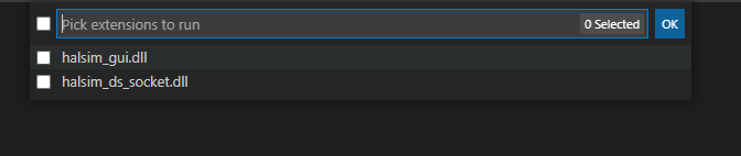
As the simulator boots up, keep an eye out... You should see another dialog pop open at the top of Visual Studio Code to select your simulator. Select "halsim_gui.dll" (note: this is different on different OSes; see documentation for details).
-
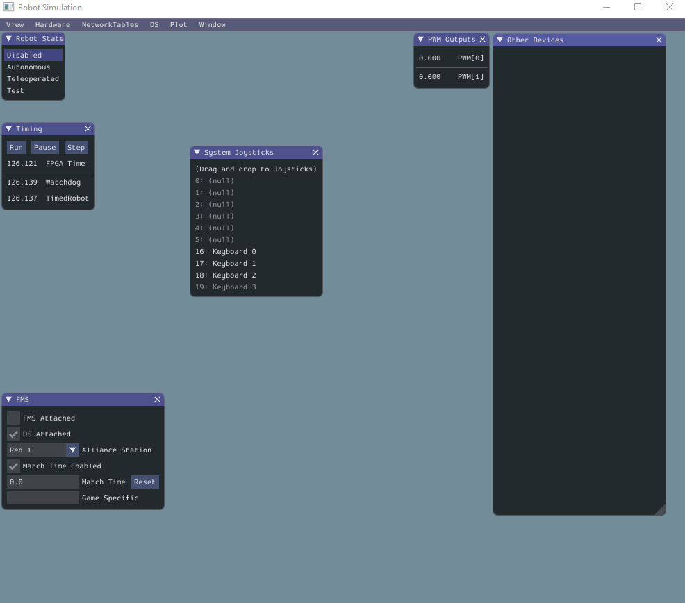
After selecting your simulator, the Robot Simulation window will come up. Here, you can set up your simulator and test-drive the robot!


To bind a joystick to the inputs the robot expects:
-
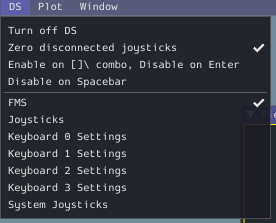
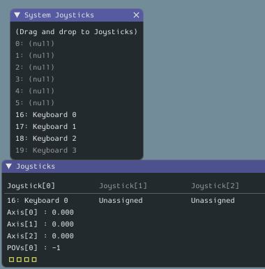
Under the "DS" menu (driver's station), select the "Joysticks" menu option to show the Joystick window. This lists all the things acting like joysticks for the robot. They will all be "Unassigned"
-
Under the same menu, select the "System Joystics" menu option to see a list of all the things plugged into your computer that could act like a joystick.
-
To use a joystick, pick something in "System Joysticks" and click-and-drag it to Joystick[0] in the "Joysticks" window.
-
If you picked a keyboard, you can change the keybindings by choosing "Keyboard (0, 1, 2, or 3) Settings" from the "DS" menu. By default, two joystick axes are bound to WS and AD, giving you WASD ("Doom-style") controls.


To see the robot on the "field":
-
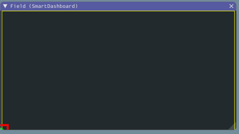
Under the "NetworkTables" menu, select "SmartDashboard > Field".
-
The robot starts in the bottom-left of the field, represented by the green arrow in a red box.

The robot starts disabled, so it won't drive. To drive, select "Teleoperated" from the "Robot State" panel near the top-left.

Once enabled, you should be able to use the joystick to move the robot around the simulated field!
The Romi is unusual in that it operates via the simulator, so WPILib always considers the Romi "simulated" (see https://www.chiefdelphi.com/t/romi-always-reports-robotbase-isreal-false/391820/2 for details). To address this, we can use sensors on board the robot to determine whether it is real or simulated. We set the EXT0 pin to "DIO" (default setting on an out-of-the-box Romi).

By then bridging the EXT0 sensor pin to ground, we create a closed switch that is open in the simulation, so the code can tell if the robot is real.

With this pin bridged, the Romi will use the encoder and gyro values from the robot chassis to drive the Field display instead of the internally-generated simulation.
- It is possible to load an image for both the field and the robot and some field parameters into the display (see docs). Change the image and get some obstacles to drive around!
- The robot's physics model is simple to the point of being unrealistic; robot will stop on a dime when power is cut to the motors and
never skids. It could be fun to replace the logic in
SimpleSimulatedChassiswith something more exciting.
The simulated robot basically works by mapping the commands going to the speed controllers to a simulation that is fed to the
simulator dashboard via NetworkTables. The simulator has these parts (wired together in Robot.java):
Field2d m_field: The field representation. This takes inPose2ddescriptions of the robot position and rotation and ships them to the dashboard via NetworkTables.SimpleSimulatedChassis m_chassis: A little widget that keeps track of imaginary encoder and gyro values for the robot on the field.PoseEstimator m_pose: An estimator for position on the field that extrapolates from wheel encoder changes and the gyro value (simulated or real values).
These are set up in initWithSensors, which is eventually run from simulationPeriodic after a quarter-second delay (giving the Romi a bit of time to detect whether EXT0 is bridged to ground). Another method, simulationPeriodic, gets called frequently. In here, we do three things:
- If we set up a simulated chassis, call
m_chassis.updateSimulationon the chassis, giving it the leftMotor and rightMotor so it knows how the robot's position should be changing. - Update the robot pose estimate via the gyro and encoder values.
- Call
m_field.setRobotPose, which communicates the new pose back to the dashboard.