AutoScribe is a drawing machine capable of making any piece of art that can be drawn with pen on paper. On a PC, it converts scalable vector graphic (SVG) images into a set of points which are sent to the Arduino and drawn.
https://www.youtube.com/watch?v=xKn2pY1tWtM
I was actually first inspired to work on this project because I enjoyed the feeling of handwritten notes, but was tired of hand cramps and sore wrists. If only there was a way to be able to combine the convenience of typing or dictating with the great feeling of pen on paper! Having seen 3D printers, laser cutters, and other CNC machines, I had the idea for a CNC drawing machine. After a quick search I found they already existed (no big suprise), but they were a bit pricy. I had some experience working with software, an Arduino, circuits, and 3D printing, how difficult would it really be to build one of these drawing machines myself? Turns out, it's actually pretty difficult -- especially when you're deadset on writing all the software yourself from scratch -- but that's why I think it's worth documenting my experience building this thing!
Along the way I found some sources which really helped get me off the ground and inspire some of my design choices:
AxiDraw
AxiDraw is a company which sells a range of similar writing and drawing machines. They seem to work extremely well and were a great proof of concept for me to justify the time I put into this project.
Instructables 4xiDraw
For most of the physical design of the machine I refrenced this instructables page titled 4xiDraw. At a glance the design is nearly the same, and I actually used the 3D models from that page in my first iteration of the hardware.
Crazy Engineer’s Drawing Robot
CNC Drawbot is another great refrence for a similar project. The page has a great bill of materials, and does things a bit different from 4xiDraw.
Improvements in this Project
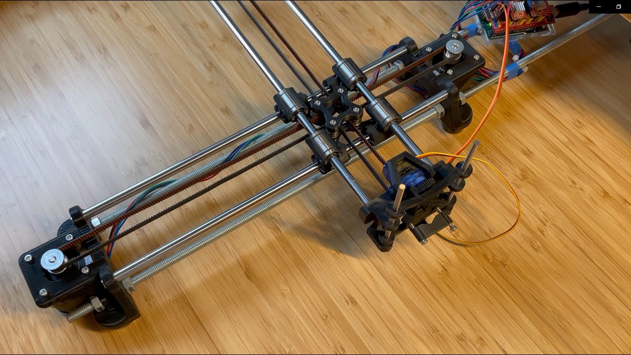
In my opinion, the physical design of the 3D printed parts for this project are quite a bit sleeker than others. I wanted to try to create a design took up minimal desk space and showed off the other pieces of hardware.
There are two main pieces of software for this project: (1) the C/C++ code that runs on the Arduino, and (2) the Python code that runs on a computer to convert SVGs into Ncode, send the Ncode to the Arduino, and actsas a GUI for easily using all the features of the drawing machine.
This is all in the in the Arduino_v2 directory, and check out the README in that directory to read more about the details of how the code works.
This code is mostly in the Frames and Tools directories. Tools contains most of the behind-the-scenes logic for converting SVGs into Ncode, sending Ncode to the Arduino, and some extra files for debugging and validating the results. Frames contains the code for the GUI. The OverSerialTests directory also has some lightweight code for testing the connection between the serial connection between the computer and the Ardiuno without needing to start the entire GUI.
The GUI was written using the tkinter package. To start the GUI run
python ./GUI.py
The GUI has 3 different tabs: Settings, Manual Control, and Drawing.

The settings tab is really just for adjusting the height of the pen, the "Up height" is the angle of the pen's servo motor when the pen is off the paper, and "Down height" is when the pen is on the paper. As the angle increases the pen gets closer to the table.
The user can use the arrow keys to fine tune these angles, and the pen on the machine will move in real time to make this process easier. When both the angles are correct pressing "Save angles" will preserve the current angles when drawing.

The manual control tab is mostly for debugging and playing around. It also uses the same pen height settings from the Settings Tab, so it's useful for checking that the pen height is correct for good ink flow while drawing.
When not manually controlling or drawing, the stepper motors of the machine are unlocked and can be moved by hand. Once "Start manual control" is clicked, the motors will lock, and then the arrow keys can be used to control the motors. Pressing a single key will only move a single motor, (for example: pressing up and right will move both motors, up and down will do nothing). Because of the layout of the machine, when only one motor is moving, the pen will move diagonally with respect to the base.
Holding the space bar will move the pen down to the paper.

The drawing tab is for selecting a .ncode file, vizualizing it, then sending to the Arduino. Clicking "Select File" will open a standard file selection dialog. Once a file is chosen, the path will appear where the "Please select a file" text is, and the "Vizualize" and "Send Ncode" buttons will unlock.
Clicking the "Vizualize" button will create a new window to see what the Ncode should look like once drawn, like this:

Usually the vizualized images will appear more pixelated than you'd expect to see from the drawing machine. The light gray lines show the path the pen will take raised off the paper, and the blue lines show the path on the paper.
Clicking "Send Ncode" will immediately begin streaming commands to the drawing machine, and while drawing pressing "Cancel" will cause the machine to immediately stop.
The models for all the 3D printed pieces are in the Models directory.
| Count | Name | Notes |
|---|---|---|
| 1 | Arduino UNO | |
| 1 | USB cable | this should come with the Arduino |
| 1 | CNC shield | connects the Arduino to the stepper motors |
| 2 | Pololu stepsticks | these go on top of the CNC shield to interface with the stepper motors |
| 2 | nema 17 stepper motors | 3D printer motors for moving the arm |
| 1 | micro servo SG90 | servo for moving the pen up and down |
| 1 | 12V 2A power supply | The USB connection from the computer won't be enough power for the stepper motors. Also, make sure this comes with the right connector to plug into the CNC shield somehow |
| 4 | 8mm smooth steel rods | whatever length you want for the drawing machine, I used 330mm |
| 8 | LM8UU | linear bearings for sliding along the smooth steel rods |
| 2 | 20-tooth GT2 pulleys | go on top of the stepper motors for moving the belts |
| 1 | GT2 belt | length depends on dimensions of your machine, can always cut one that's too long |
| 10 | F623ZZ bearings | ball bearings for where the belt freely spins through the hub and by the pen |
| 2 | M10 threaded rods | these go through the two ends of the base to hold it together (have to be as long as the smooth steel rods) |
| 8 | M10 nuts | two for each end of each rod |
| 8 | M10 washers | one for each M10 nut |
| X | Pack of M3 30mm, 16mm, 6mm screws, nuts, and washers | Need at least 8 of each screw, 12 nuts, and 4 washers |
| 2 | 4mm OD x 100mm length rod | I used steel, 4xiDraw recommends carbon fiber. Pen slides along these. |
All the info for downloading the software and getting started yourself.
Specifications: Developed on Windows 10 using Python version 3.9.1
First clone the repo:
git clone https://github.com/n-ponto/AutoScribe.git
Then install the Python modules:
pip install -r requirements.txt
I recommend not trying to use Anaconda. Why not Anaconda?
Anaconda is a great tool to aid in Python package management.
I recommend not using Anaconda because there are some issues with installing the bezier module within the Anaconda environment. This is only required for the ParseSvg.py script, so if you don't plan to create any of your own images and just rely on the ncode files already provided in this repo, then there's no need to install the bezier module.
In order to upload the C++ code to the Aruino, the easiest way is to use the Arduino IDE. From the Aruino IDE, you'll want to open the main file at Arduino_v2/Arduino_v2.ino. This should open the entire Arduino project (all the files in the Arduino_v2 folder). Then upload the code by clicking the right arrow in the top left corner of the IDE.
Creating an SVG file is the first step in drawing something. All that really matters in this file is the Path objects, because these are what get turned into Ncode. I like using the free software Inkscape for making and working with SVGs. Inkscape has a built-in "Trace Bitmap" function to get a SVG path from a standard raster image. Usually I find that I need to manually touch up the SVG paths a bit after using this tool.
Once you have an SVG of a file you'd like to draw, it needs to be converted to Ncode. To do this, run:
python ParseSvg.py path/to/file.svg
ParseSvg.py can also directly vizualize the ncode or can take a custom save path for the Ncode file. For more info, use:
py ParseSvg.py -h