This repository contains my solutions to the assignments of the Microprocessor and Assembly Laboratory course.
The instructions for the assignments are in the docs/instructions.pdf file. For each assignment solution, there is
sometimes a report.pdf or prepatory_report.pdf that covers the background knowledge needed for that assignment in
Persian.
The assignments use the Arduino MEGA 2560 microcontroller, which is based on Atmel ATmega2560. The board specs are as follows:
| Feature | Specification |
|---|---|
| Microcontroller | ATMega 2560 |
| Operating Voltage | 5 V |
| Input Voltage (suggested) | 7-12 V |
| Input Voltage (limits) | 6-20 V |
| Digital I/O Pins | 54 (15 PWM) |
| Analog Pins | 16 |
| DC Current for 3.3V Pins | 20 mA |
| DC Current for 5V Pins | 50 mA |
| Flash Memory | 256 KB (8KB used by bootloader) |
| SRAM | 8 KB |
| Clock Rate | 16 MHz |
Unlike my Arduino-IoT-Arcade repository, circuits for these labs are
not physically assembled but rather simulated in the Proteus Design suite. Thus, for each lab, their pdsprj Proteus
source code is available in their directory.
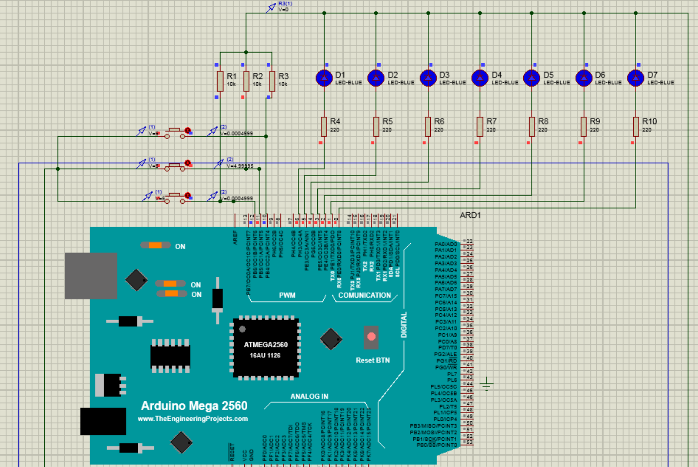
A simple circuit with 3 buttons and some LEDs is created. At first, all LEDs are off. The first button turns on LEDs from right to left. The second button turns them on in reverse order. The last button turns them all off.
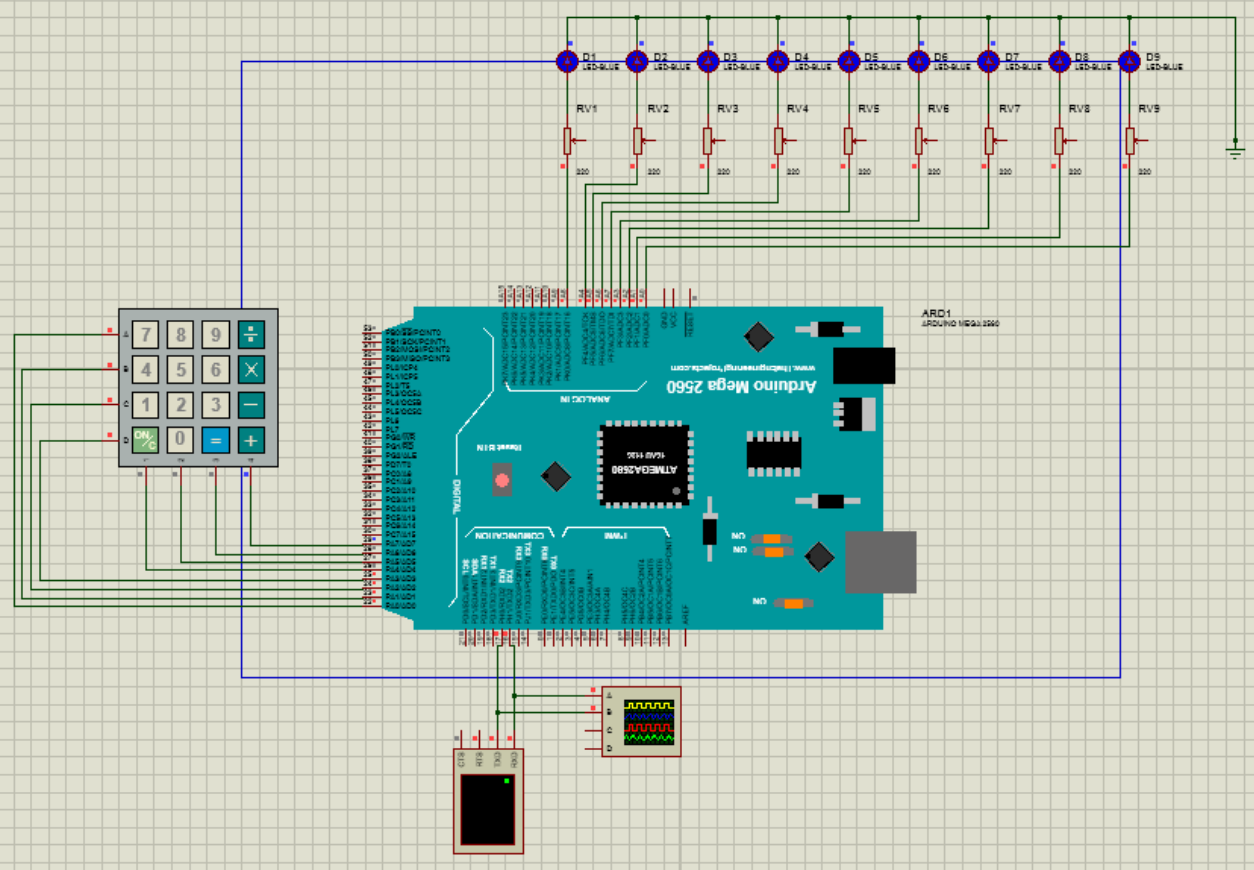
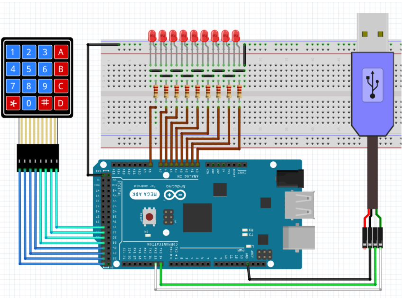
- [Q1_and_2.ino] 9 LEDs and a keypad are connected to the microcontroller. Pressing any digit key leads to turning on its corresponding LED. The pressed key also appears on the virtual terminal. Pressing the 'C' key turns all LEDs off.
- [Q3.ino] This time, the input is received from the virtual terminal, and again, the corresponding LED is turned on.
- An LCD is connected to the microcontroller. A "Hello World" message is printed on the LCD screen. Every second, the message is moved one character to the right, and when it reaches the end of the line, it continues from the next line. This is done repeatedly.
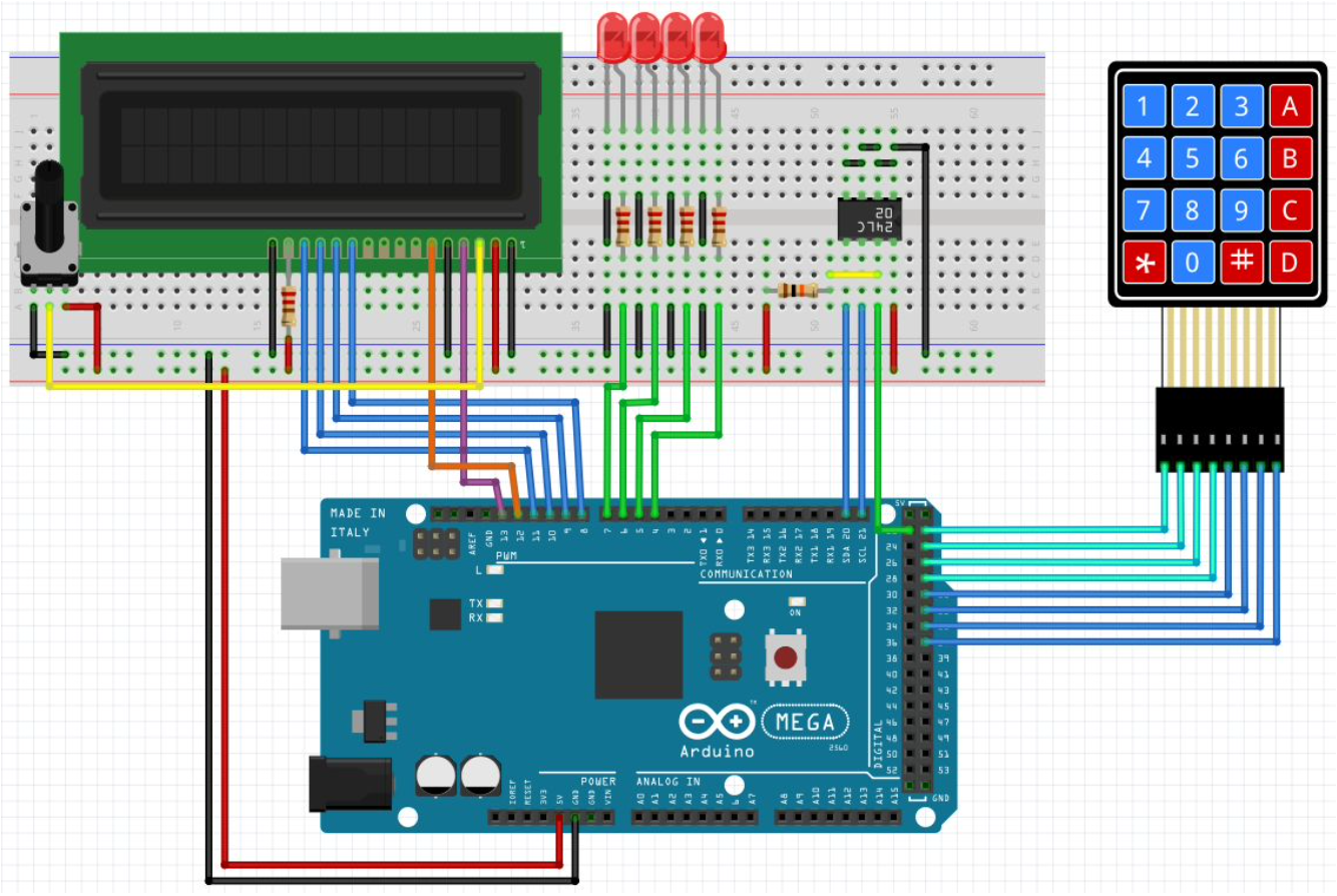
- A keypad is added to the circuit. An input is entered by the user, and it is checked against some predefined password. Depending on whether the input string is correct or wrong, an appropriate message is displayed on the screen.
- A calculator is developed with the previous components. The inputs are received using the keypad, and the outputs are displayed on the LCD.
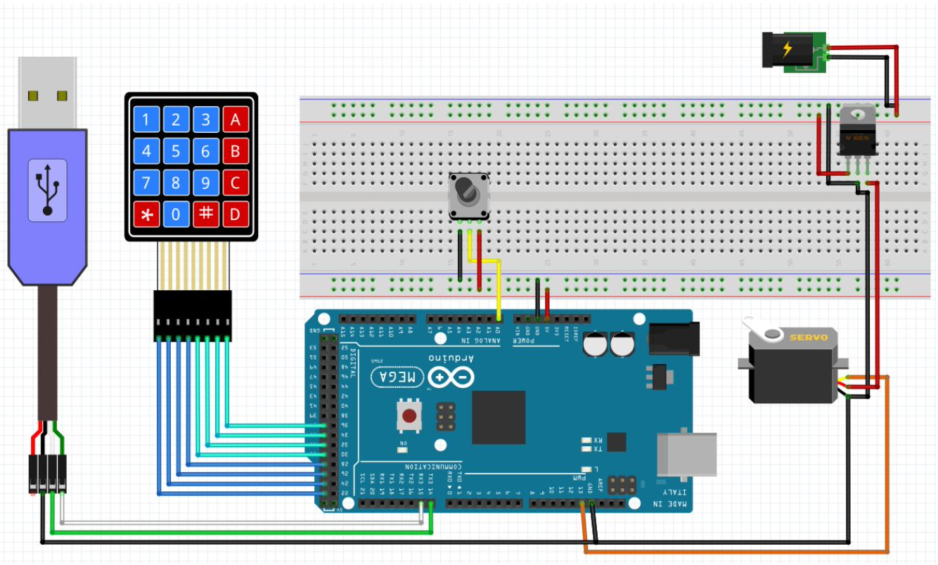
- [Q1.ino] A servo motor is connected to the microcontroller. It continuously rotates from degree 0 to 180 and back.
- [Q2.ino] A keypad is added to the circuit. The user can enter a degree with the keypad, and the servo motor rotates to that degree.
- [Q3.ino] This time, the user specifies their desired degree with the serial monitor.
- [Q4.ino] A potentiometer is connected to the previous circuit. This script changes the degree of the servo motor based on the value of the potentiometer.
- An oscilloscope is connected to the servo motor. The fundamental period and duty cycle of its wave are calculated for different rotation degrees.
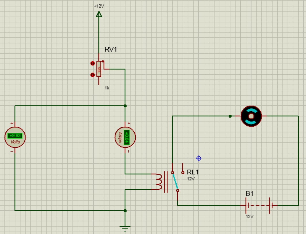
- A motor is set up using a relay. Whenever the motor is off, an LED is turned on, and vice versa.
- [Vending Machine] A vending machine is mimicked using the microcontroller. A certain 7-digit password can be entered using the keypad to unlock the imaginary vending machine, using a servo motor that rotates 90 degrees. A set of servo motors also rotate so that "imaginary" trays are open to put products in them. The LED is turned off in this state. Pushing a button locks the vending machine door again and turns off all LEDs. Users can now enter the ID of a product and retrieve it when its corresponding servo motor rotates to release it. Everything is displayed on the LCD.
- [Safe] A safe is created using the microcontroller. The user can input their password using the keypad, then the imaginary "door" opens using the servo motor, and an LED is turned on, indicating that the door is open. The user can close the door by pressing a button. A timer is set up to close the door after a certain amount of time. This amount of time can be set using the keypad by the user. A buzzer buzzes whenever the door is opening or closing. On the LCD, the correctness of the input password, the status of the door, and the timer for closing the door are displayed.
- A simple washing machine is mimicked using the microcontroller and its EEPROM. The washing machine has 4 steps:
- Pre-wash
- Wash with washing liquid
- Wash with water
- Dry
- The time for each of these steps can be configured by the user. For each setup, there's an LED that indicates the washing machine is in that step.
- The device shows the default mode on an LCD connected to the microcontroller, and the user can change their preferred default mode using a keypad. Their preferences are saved on the EEPROM, so when the power source is disconnected and reconnected again, their preferences are preserved.
- The user can choose a mode for the washing machine to run in that mode and start or stop the washing machine. The time left to finish the current task is displayed on the LCD. The end of all stages is also announced by turning all on LEDs and printing a message on the LCD.
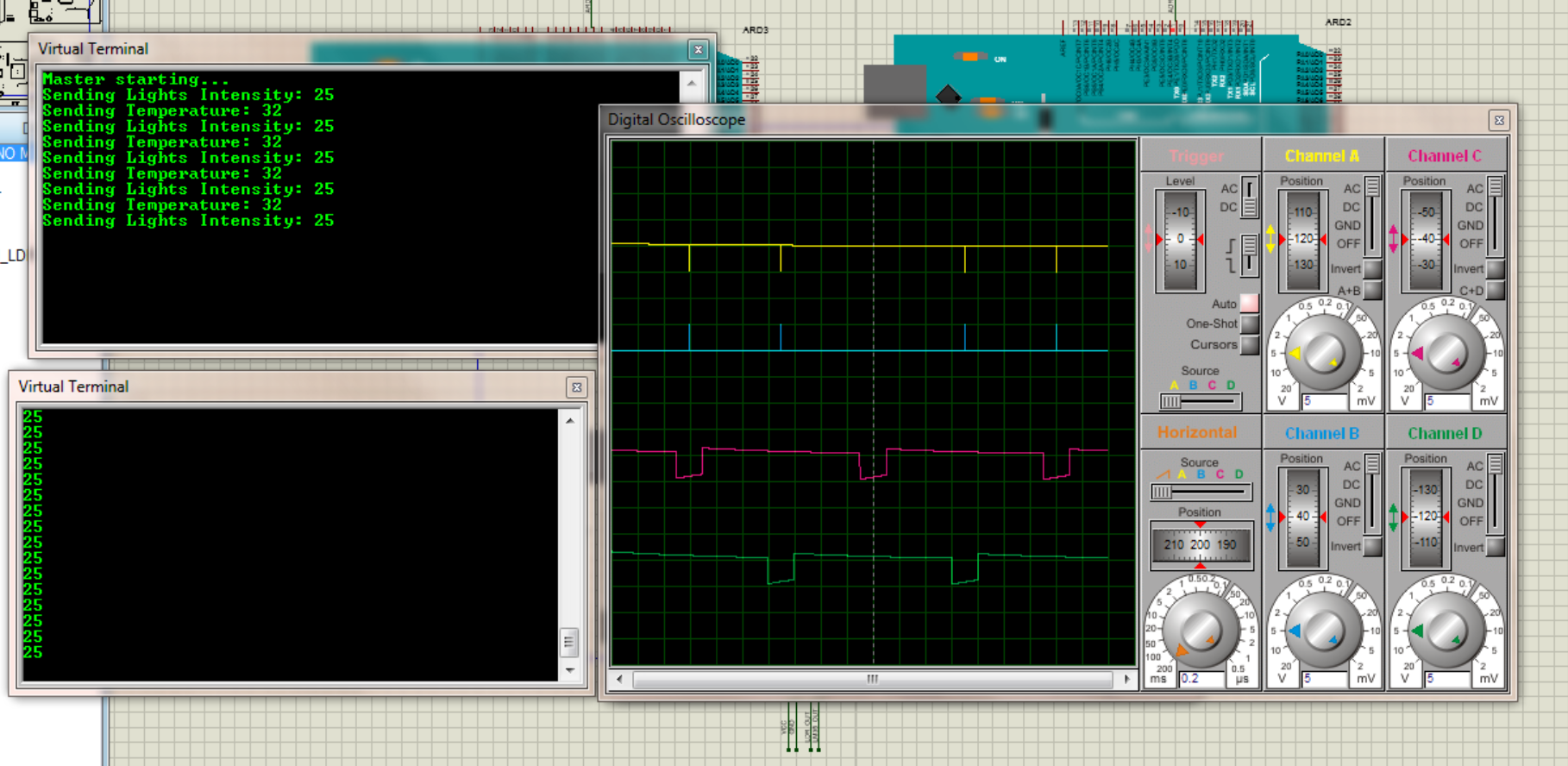
- [Q1.ino] An SPI connection between two Arduino Mega2560 microcontrollers is set up. The master microcontroller sends a "Hello World" message every second to the slave. The output waves for the SCLK, MOSI, and SS pins are visualized in an oscilloscope.
- [Q2.ino] The previous scripts are changed so that the slave, for each received message, returns a "Hi!" message.
- [Q4.ino] An LDR and an LM35 are connected to the microcontrollers to measure the brightness and temperature of the environment. The messages sent and received by microcontrollers are switched from the string to the LDR and LM35 measured values
- [Q1.ino] A button and a speaker are added to the microcontroller. The script plays the Jingle Bells melody using the pitches.h module.
- [Q2.ino] The note frequency in the previous script is tuned.
- [Q3.ino] A potentiometer is added to the circuit. This potentiometer controls the pitch of the melody.
- [Q4.ino] The "Ode to Joy" is played.
- [Q5.ino] The Imperial March is played.
- Course: Microprocessor and Assembly
- University: Amirkabir University of Technology
- Semester: Fall 2020
Let me know if you have any questions.
