- Table of Contents
- Installation
- Package Structure
Install from github:
python3 -m pip install git+https://github.com/gumyr/cq_warehouse.git#egg=cq_warehouse
Note that cq_warehouse requires the development version of cadquery (see Installing CadQuery). Also note that cq_warehouse uses the pydantic package for input validation which requires keyword arguments (e.g. num_teeth=16).
The cq_warehouse package contains the following sub-packages:
- sprocket : a parametric sprocket generator
- chain : a parametric chain generator
- drafting : a set of methods used for documenting cadquery objects
- fastener : a parametric threaded fastener generator
- extensions : a set of enhancements to the core cadquery system
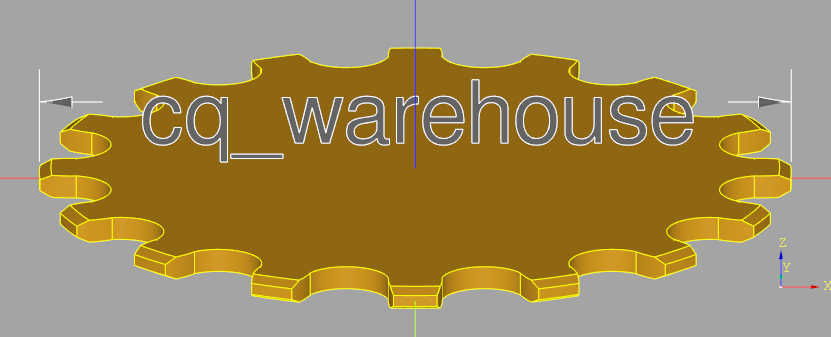
A sprocket can be generated and saved to a STEP file with just four lines
of python code using the Sprocket class:
import cadquery as cq
from cq_warehouse.sprocket import Sprocket

sprocket32 = Sprocket(num_teeth=32)
cq.exporters.export(sprocket32.cq_object,"sprocket.step")
How does this code work?
- The first line imports cadquery CAD system with the alias cq
- The second line imports the Sprocket class from the sprocket sub-package of the cq_warehouse package
- The third line instantiates a 32 tooth sprocket named
sprocket32
- The fourth line uses the cadquery exporter functionality to save the generated sprocket object in STEP format
Note that instead of exporting sprocket32, sprocket32.cq_object is exported as sprocket32 contains much more than just the raw CAD object - it contains all of the parameters used to generate this sprocket - such as the chain pitch - and some derived information that may be useful - such as the chain pitch radius.
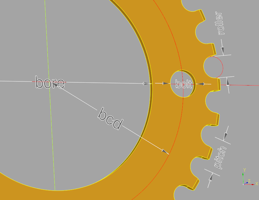
Most of the Sprocket parameters are shown in the following diagram:
The full set of Sprocket input parameters are as follows:
num_teeth(int) : the number of teeth on the perimeter of the sprocket (must be >= 3)chain_pitch(float) : the distance between the centers of two adjacent rollers - default 1/2" - (pitch in the diagram)roller_diameter(float) : the size of the cylindrical rollers within the chain - default 5/16" - (roller in the diagram)clearance(float) : the size of the gap between the chain's rollers and the sprocket's teeth - default 0.0thickness(float) : the thickness of the sprocket - default 0.084"bolt_circle_diameter(float) : the diameter of the mounting bolt hole pattern - default 0.0 - (bcd in the diagram)num_mount_bolts(int) : the number of bolt holes - default 0 - if 0, no bolt holes are added to the sprocketmount_bolt_diameter(float) : the size of the bolt holes use to mount the sprocket - default 0.0 - (bolt in the diagram)bore_diameter(float) : the size of the central hole in the sprocket - default 0.0 - if 0, no bore hole is added to the sprocket (bore in the diagram)
NOTE Default parameters are for standard single sprocket bicycle chains.
The sprocket in the diagram was generated as follows:
MM = 1
chain_ring = Sprocket(
    num_teeth = 32,
    clearance = 0.1*MM,
    bolt_circle_diameter = 104*MM,
    num_mount_bolts = 4,
    mount_bolt_diameter = 10*MM,
    bore_diameter = 80*MM
)
NOTE
Units in cadquery are defined so that 1 represents one millimeter but MM = 1 makes this
explicit.
In addition to all of the input parameters that are stored as instance variables within the Sprocket instance there are four derived instance variables:
pitch_radius(float) : the radius of the circle formed by the center of the chain rollersouter_radius(float) : the size of the sprocket from center to tip of the teethpitch_circumference(float) : the circumference of the sprocket at the pitch radcq_object(cq.Workplane) : the cadquery sprocket object
The Sprocket class defines two static methods that may be of use when designing systems with sprockets: calculation of the pitch radius and pitch circumference as follows:
@staticmethod
def sprocket_pitch_radius(num_teeth:int, chain_pitch:float) -> float:
    """
    Calculate and return the pitch radius of a sprocket with the given number of teeth
    and chain pitch

    Parameters
    ----------
    num_teeth : int
        the number of teeth on the perimeter of the sprocket
    chain_pitch : float
        the distance between two adjacent pins in a single link (default 1/2 INCH)
    """

@staticmethod
def sprocket_circumference(num_teeth:int, chain_pitch:float) -> float:
    """
    Calculate and return the pitch circumference of a sprocket with the given number of
    teeth and chain pitch

    Parameters
    ----------
    num_teeth : int
        the number of teeth on the perimeter of the sprocket
    chain_pitch : float
        the distance between two adjacent pins in a single link (default 1/2 INCH)
"""Normally the tip of a sprocket tooth has a circular section spanning the roller pin sockets
on either side of the tooth tip. In this case, the tip is chamfered to allow the chain to
easily slide over the tooth tip thus reducing the chances of derailing the chain in normal
operation. However, it is valid to generate a sprocket without this flat
section by
increasing the size of the rollers. In this case, the tooth tips will be spiky
and
will not be chamfered.
A chain wrapped around a set of sprockets can be generated with the Chain class by providing
the size and locations of the sprockets, how the chain wraps and optionally the chain parameters.
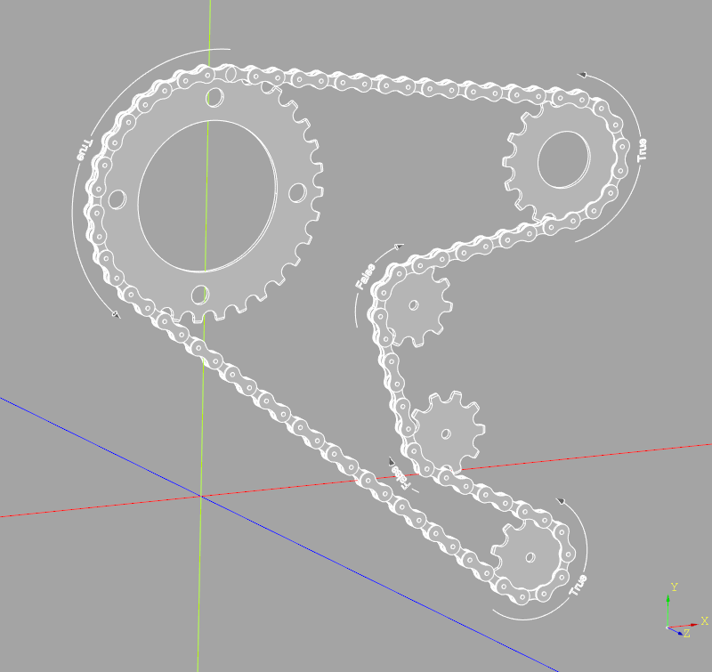
For example, one can create the chain for a bicycle with a rear deraileur as follows:
import cadquery as cq
import cq_warehouse.chain as Chain

derailleur_chain = Chain(
    spkt_teeth=[32, 10, 10, 16],
    positive_chain_wrap=[True, True, False, True],
    spkt_locations=[
        (0, 158.9*MM, 50*MM),
        (+190*MM, 0, 50*MM),
        (+190*MM, 78.9*MM, 50*MM),
        (+205*MM, 158.9*MM, 50*MM)
    ]
)
if "show_object" in locals():
show_object(derailleur_chain.cq_object, name="derailleur_chain")The complete set of input parameters are:
spkt_teeth(list of int) : a list of the number of teeth on each sprocket the chain will wrap aroundspkt_locations(list of cq.Vector or tuple(x,y) or tuple(x,y,z)) : the location of the sprocket centerspositive_chain_wrap(list of bool) : the direction chain wraps around the sprockets, True for counter clock wise viewed from positive Zchain_pitch(float) : the distance between two adjacent pins in a single link - default 1/2"roller_diameter(float) : the size of the cylindrical rollers within the chain - default 5/16"roller_length(float) : the distance between the inner links, i.e. the length of the link rollers - default 3/32"link_plate_thickness(float) : the thickness of the link plates (both inner and outer link plates) - default 1mm
The chain is created on the XY plane (methods to move the chain are described below) with the sprocket centers being described by:
- a two dimensional tuple (x,y)
- a three dimensional tuple (x,y,z) which will result in the chain being created parallel
to the XY plane, offset by
z
- the cadquery Vector class which will displace the chain by Vector.z
To control the path of the chain between the sprockets, the user must indicate the desired
direction for the chain to wrap around the sprocket. This is done with the positive_chain_wrap
parameter which is a list of boolean values - one for each sprocket - indicating a counter
clock wise or positive angle around the z-axis when viewed from the positive side of the XY
plane. The following diagram illustrates the most complex chain path where the chain
traverses wraps from positive to positive, positive to negative, negative to positive and
negative to negative directions (positive_chain_wrap values are shown within the arrows
starting from the largest sprocket):
Note that the chain is perfectly tight as it wraps around the sprockets and does not support any slack. Therefore, as the chain wraps back around to the first link it will either overlap or gap this link - this can be seen in the above figure at the top of the largest sprocket. Adjust the locations of the sprockets to control this value.
In addition to all of the input parameters that are stored as instance variables within the Chain instance there are seven derived instance variables:
pitch_radii(list of float) : the radius of the circle formed by the center of the chain rollers on each sprocketchain_links(float) : the length of the chain in linksnum_rollers(int) : the number of link rollers in the entire chainroller_loc(list of cq.Vector) : the location of each roller in the chainchain_angles(list of tuple(float,float)) : the chain entry and exit angles in degrees for each sprocketspkt_initial_rotation(list of float) : angle in degrees to rotate each sprocket in-order to align the teeth with the gaps in the chaincq_object(cq.Assembly) : the cadquery chain object
The Chain class defines two methods:
- a static method used to generate chain links cadquery objects, and
- an instance method that will build a cadquery assembly for a chain given a set of sprocket cadquery objects. Note that the make_link instance method uses the @cache decorator to greatly improve the rate at links can be generated as a chain is composed of many copies of the links.
def assemble_chain_transmission(self,spkts:list[Union[cq.Solid, cq.Workplane]]) -> cq.Assembly:
    """
    Create the transmission assembly from sprockets for a chain

    Parameters
    ----------
    spkts : list of cq.Solid or cq:Workplane
        the sprocket cadquery objects to combine with the chain to build a transmission
    """

@staticmethod
@cache
def make_link(
        chain_pitch:float = 0.5*INCH,
        link_plate_thickness:float = 1*MM,
        inner:bool = True,
        roller_length:float = (3/32)*INCH,
        roller_diameter:float = (5/16)*INCH
    ) -> cq.Workplane:
    """
    Create either inner or outer link pairs.  Inner links include rollers while
    outer links include fake roller pins.

    Parameters
    ----------
    chain_pitch : float = (1/2)*INCH
        # the distance between the centers of two adjacent rollers
    link_plate_thickness : float = 1*MM
        # the thickness of the plates which compose the chain links
    inner : bool = True
        # inner links include rollers while outer links include roller pins
    roller_length : float = (3/32)*INCH,
        # the spacing between the inner link plates
    roller_diameter : float = (5/16)*INCH
        # the size of the cylindrical rollers within the chain
    """
Once a chain or complete transmission has been generated it can be re-oriented as follows:
two_sprocket_chain = Chain(
    spkt_teeth = [32, 32],
    positive_chain_wrap = [True, True],
    spkt_locations = [ (-5*INCH, 0), (+5*INCH, 0) ]
)
relocated_transmission = two_sprocket_chain.assemble_chain_transmission(
    spkts = [spkt32.cq_object, spkt32.cq_object]
).rotate(axis=(0,1,1),angle=45).translate((20, 20, 20))Two future enhancements are being considered:
- Non-planar chains - If the sprocket centers contain
zvalues, the chain would follow the path of a spline between the sockets to approximate the path of a bicycle chain where the front and read sprockets are not in the same plane. Currently, thezvalues of the first sprocket define thezoffset of the entire chain. - Sprocket Location Slots - Typically on or more of the sprockets in a chain transmission will be adjustable to allow the chain to be tight around the sprockets. This could be implemented by allowing the user to specify a pair of locations defining a slot for a given sprocket indicating that the sprocket location should be selected somewhere along this slot to create a perfectly fitting chain.
A class used to document cadquery designs by providing three methods that create objects that can be included into the design illustrating marked dimension_lines or notes.
For example:
import cadquery as cq
from cq_warehouse.drafting import Draft

# Import an object to be dimensioned
mystery_object = cq.importers.importStep("mystery.step")

# Create drawing instance with appropriate settings
metric_drawing = Draft(decimal_precision=1)

# Create an extension line from corners of the part
length_dimension_line = metric_drawing.extension_line(
    object_edge=mystery_object.faces("<Z").vertices("<Y").vals(),
    offset=10.0,
    tolerance=(+0.2, -0.1),
)

if "show_object" in locals():
    show_object(mystery_object, name="mystery_object")
    show_object(length_dimension_line, name="length_dimension_line")
To illustrate some of the capabilities of the drafting package, a set of dimension lines, extension lines and callouts were applied to a cadquery part with no prior knowledge of any of the dimensions:
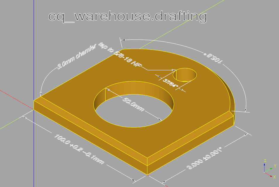 One could define three instances of the Draft class, one for each of the XY, XZ and YZ planes and generate a set of dimensions on each one. By enabling one of these planes at a time and exporting svg images traditional drafting documents can be generated.
When generating dimension lines there are three possibilities depending on the measurement and Draft attributes (described below):
- The label text (possibly including units and tolerances) and arrows fit within the measurement,
- The label text but not the arrows fit within the measurement, or
- Neither the text nor the arrows fit within the measurements. Cases 1 and 2 are shown in the above example. In case 3, the label will be attached to one of the external arrows.
These three possibilities are illustrated below with both linear and arc extension lines:
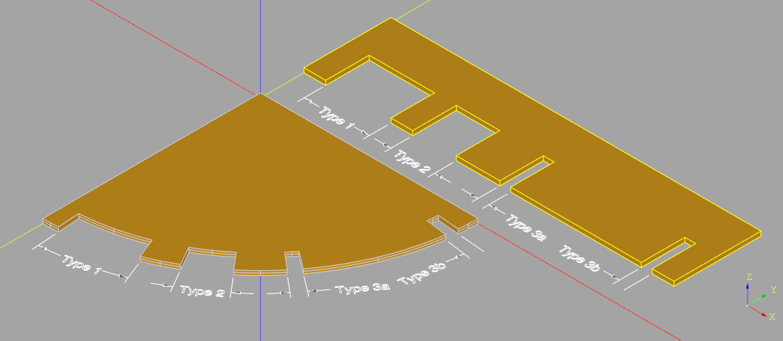 Note that type 3b can only be created by disabling the end arrow - see the arrows parameter below.
The Draft class contains a set of attributes used to describe subsequent dimension_line(s), extension_line(s) or callout(s). The full list is as follows:
font_size(float = 5.0) : the size of the text in dimension lines and calloutscolor(Optional[cq.Color]) : the color of text, extension lines and arrows (defaults to (0.25, 0.25, 0.25))arrow_diameter(float = 1.0) : the maximum diameter of the conical arrows - note that if a dimension line follows the provided path even if it's non-lineararrow_length(float = 3.0) : arrow head lengthlabel_normal(Optional[VectorLike]) : text and extension line plane normal - default to XY planeunits(Literal["metric", "imperial"]) : unit of measurement - default "metric"number_display(Literal["decimal", "fraction"]) : display numbers as decimals or fractions - defaults to "decimal"display_units(bool) : control the display of units with numbers - default to Truedecimal_precision(int = 2) : number of decimal places when displaying numbersfractional_precision(int = 64) : maximum fraction denominator - note it must be a factor of 2
The three public methods that the Draft class defines are described below. Note that both dimension_line ane extension_line support arcs as well as linear measurements - to be exact, the shown measurement is the length of the input path or object edge which could be an arbitrary shape like a spline. If this path or object_edge is part of a circle the size of the arc in degrees may be displayed instead of the length.
Typically used for (but not restricted to) inside dimensions, a dimension line often as arrows on either side of a dimension or label. The full set of input parameters are as follows:
path(PathDescriptor) : a very general type of input used to describe the path the dimension line will follow wherePathDescriptor = Union[ cq.Wire, cq.Edge, list[Union[cq.Vector, cq.Vertex, Tuple[float, float, float]]]- i.e. a list of points or cadquery edge or wire either extracted from a part or created by the user.label(Optional[str]) : a text string which will replace the length (or arc length) that would otherwise be extracted from the provided path. Providing a label is useful when illustrating a parameterized input where the name of an argument is desired not an actual measurement.arrows(Tuple[bool,bool]) : a pair of boolean values controlling the placement of the start and end arrows - both default to True.tolerance(Optional[Union[float,Tuple[float,float]]]) : an optional tolerance value to add to the extracted length value. If a single tolerance value is provided it is shown as ± the provided value while a pair of values are shown as separate + and - values.label_angle(bool) : a flag - defaulting to False - indicating that instead of an extracted length value, the size of the circular arc extracted from the path should be displayed in degrees.
dimension_line returns a cadquery Assembly object.
Typically used for (but not restricted to) outside dimensions, with a pair of lines extending from the edge of a part to a dimension line. The full set of input parameters are as follows:
object_edge(PathDescriptor) : a very general type of input defining the object to be dimensioned. Typically this value would be extracted from the part but is not restricted to this use.offset(float) : a distance to displace the dimension line from the edge of the object.label(Optional[str]) : a text string which will replace the length (or arc length) that would otherwise be extracted from the provided path. Providing a label is useful when illustrating a parameterized input where the name of an argument is desired not an actual measurement.arrows(Tuple[bool,bool]) : a pair of boolean values controlling the placement of the start and end arrows - both default to True.tolerance(Optional[Union[float,Tuple[float,float]]]) : an optional tolerance value to add to the extracted length value. If a single tolerance value is provided it is shown as ± the provided value while a pair of values are shown as separate + and - values.label_angle(bool) : a flag - defaulting to False - indicating that instead of an extracted length value, the size of the circular arc extracted from the path should be displayed in degrees.
extension_line returns a cadquery Assembly object.
A text box with or without a tail pointing to another object used to provide extra information to the reader. The full set of input parameters are as follows:
label(str) : the text to place within the callout - note that including a\nin the text string will split the text over multiple lines.tail(Optional[PathDescriptor]) : an optional tail defined as above - note that if provided the text origin will be the start of the tail.origin(Optional[PointDescriptor]) : a very general definition of anchor point of the text defined asPointDescriptor = Union[cq.Vector, cq.Vertex, Tuple[float, float, float]]justify(Literal["left", "center", "right"]) : text alignment which defaults to "left"
callout returns a cadquery Assembly object.
Many mechanical designs will contain threaded fasteners of some kind, either in a threaded hole or threaded screws or bolts holding two or more parts together. The fastener sub-package provides a set of classes with which raw threads can be created such that they can be integrated into other parts as well as a set of classes that create many different types of nuts, screws or bolts. Here is a list of the classes provided:
- Nut - the base nut class
- HexNut - a derived class providing hexagonal nuts
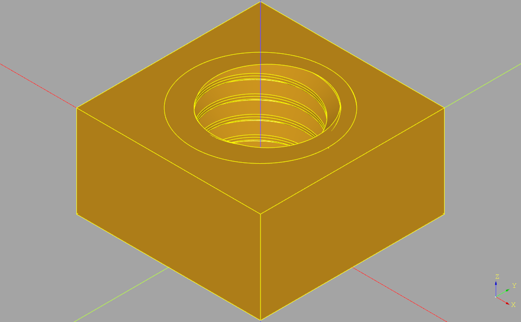
- SquareNut - a derived class providing square nuts
- Screw - the base screw class
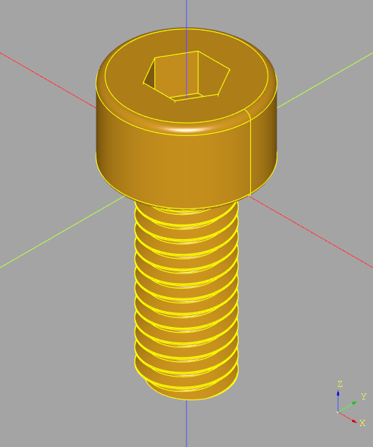
- SocketHeadCapScrew - a derived class providing socket head cap screws
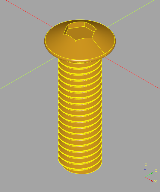
- ButtonHeadCapScrew - a derived class providing button head cap screws
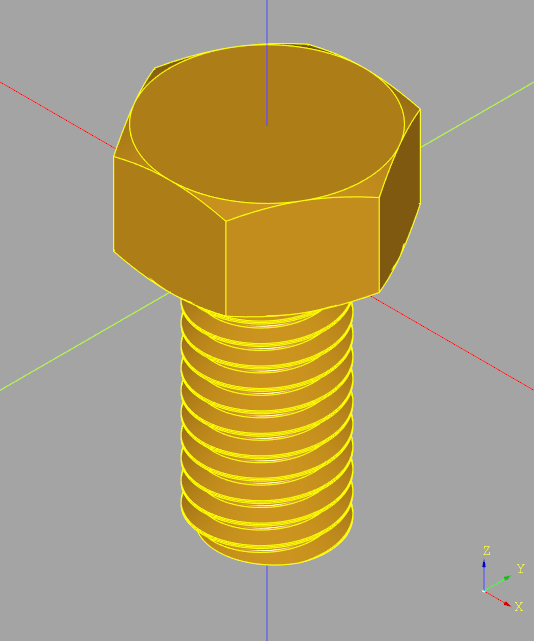
- HexBolt- a derived class providing hexagonal bolts
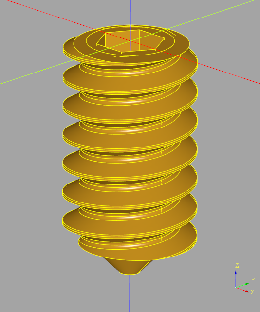
- SetScrew - a derived class providing setscrews
- Thread - the base thread class
- ExternalThread - a derived class providing threads on screws
- InternalThread - a derived class providing threads on nuts
Use of the base classes is only required by those wishing to create new types of nuts or screws. See Extending the fastener sub-package for guidance on how to easily add new sizes or entirely new types of fasteners.
The following example creates a variety of different sized fasteners:
import cadquery as cq
from cq_warehouse.fastener import HexNut, SocketHeadCapScrew, SetScrew
MM = 1
IN = 25.4 * MM

nut = HexNut(size="1/4-20")
setscrew = SetScrew(size="#6-32", length=(1 / 4) * IN)
capscrew = SocketHeadCapScrew(size="M3-0.5", length=10 * MM)
Both metric and imperial sized standard fasteners are directly supported by the fastener sub-package. To display the available standard sizes use the metric_sizes() or imperial_sizes() methods as follows:
print(f"Standard metric hex nut sizes: {HexNut.metric_sizes()}")
print(f"Standard imperial hex nut sizes: {HexNut.imperial_sizes()}")
Threaded parts are complex for CAD systems to create and significantly increase the storage requirements thus making the system slow and difficult to use. To minimize these requirements all of the fastener classes have a simple boolean parameter that when True doesn't create actual threads at all. Such simple parts have the same overall dimensions and such that they can be used to check for fitment without dramatically impacting performance.
CQ-editor
⚠️ Set the Preferences ➡️ 3D Viewer ➡️ Deviation parameter to 0.01 to avoid crashes due to memory over-consumption when working with threads
The classes that generate actual fasteners provide two interfaces:
- An interface for standard sizes with a string
sizeparameter to select a standard metric or imperial sized fastener. Allsizeparameters are composed of the major diameter, a dash separator, and the thread pitch or TPI. Metric sizes start with capital M (e.g. 'M3-0.5') while imperial sizes can be either a number/fraction (e.g. '5/8-18') or a # followed by the gauge (e.g. '#8-32'). Once the fastener has been instantiated a set of instance variables will be created which contain all of the data used in its creation. These values can be used to orient the fastener in an assembly. Note that all standard sizes are parameterized with.csvfiles and are therefore easy to augment. - An interface for custom sizes where each of the dimensions required to create the fastener is provided directly.
All of the fasteners default to right-handed thread but each of them provide a hand sting parameter which can either be "right" or "left".
All of the fastener classes provide a cq_object instance variable which contains the cadquery Solid object.
The following sections describe each of the provided classes.
As the base class of all other nut classes it isn't intended for end users.
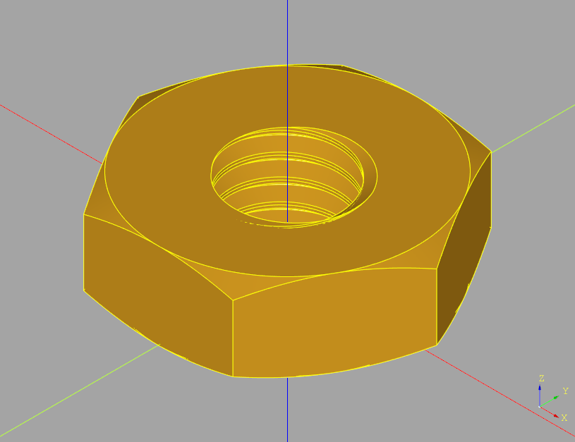
HexNut creates hexagonal nuts of either standard or custom sizes. Standard sizes are described by the 'imperial_hex_parameters.csv' or 'metric_hex_parameters.csv' files. The parameters are:
size(str) : standard sizeshand(Literal["right", "left"] = "right") : thread directionsimple(bool = False) : simplify thread
or
width(float) : width across the flat sectionsthread_diameter(float) : major thread diameterthread_pitch(float) : thread pitch (IN / TPI for imperial)thickness(float) : maximum nut thicknesshand(Literal["right", "left"] = "right") : thread directionsimple(bool = False) : simplify thread
This class exposes instance variables for the detailed input parameters as well as:
cq_object(cq.Solid) : cadquery Solid object
SquareNut creates square nuts of either standard or custom sizes. Standard sizes are described by the 'imperial_hex_parameters.csv' or 'metric_hex_parameters.csv' files as the width across the flat sections is the same as for hex nuts. The parameters are:
size(str) : standard sizeshand(Literal["right", "left"] = "right") : thread directionsimple(bool = False) : simplify thread
or
width(float) : widththread_diameter(float) : major thread diameterthread_pitch(float) : thread pitch (IN / TPI for imperial)thickness(float) : maximum nut thicknesshand(Literal["right", "left"] = "right") : thread directionsimple(bool = False) : simplify thread
This class exposes instance variables for the detailed input parameters as well as:
cq_object(cq.Solid) : cadquery Solid object
As the base class of all other screw and bolt classes it isn't intended for end users.
SocketHeadCapScrew creates socket head cap screws of either standard or custom sizes. Standard sizes are described by the 'imperial_socket_head_cap_screw_parameters.csv' or 'metric_socket_head_cap_screw_parameters.csv' files. The parameters are:
size(str) : standard sizeslength(float) : distance from base of head to tip of threadhand(Literal["right", "left"] = "right") : thread directionsimple(bool = False) : simplify thread
or
length(float) : distance from base of head to tip of threadhead_diameter(float) : maximum head diameterhead_height(float) : maximum head height (+Z direction)thread_diameter(float) : major thread diameterthread_pitch(float) : thread pitch (IN / TPI for imperial)thread_length(float) : length of the threaded sectionsocket_size(float) : distance between flats within the socketsocket_depth(float) : socket depthhand(Literal["right", "left"] = "right") : thread directionsimple(bool = False) : simplify thread
This class exposes instance variables for the detailed input parameters as well as:
cq_object(cq.Solid) : cadquery Solid objecthead(cq.Solid) : the screw head cadquery Solid objectshank(cq.Solid) : the shank cadquery Solid object
ButtonHeadCapScrew creates button head cap screws of either standard or custom sizes. Standard sizes are described by the 'imperial_button_head_cap_screw_parameters.csv' or 'metric_button_head_cap_screw_parameters.csv' files. The parameters are:
size(str) : standard sizeslength(float) : distance from base of head to tip of threadhand(Literal["right", "left"] = "right") : thread directionsimple(bool = False) : simplify thread
or
length(float) : distance from base of head to tip of threadhead_diameter(float) : maximum head diameterhead_height(float) : head height (+Z direction) without socketthread_diameter(float) : major thread diameterthread_pitch(float) : thread pitch (IN / TPI for imperial)thread_length(float) : length of the threaded sectionsocket_size(float) : distance between flats within the socketsocket_depth(float) : socket depthhand(Literal["right", "left"] = "right") : thread directionsimple(bool = False) : simplify thread
This class exposes instance variables for the detailed input parameters as well as:
cq_object(cq.Solid) : cadquery Solid objecthead(cq.Solid) : the screw head cadquery Solid objectshank(cq.Solid) : the shank cadquery Solid object
HexBolt creates hexagonal bolts of either standard or custom sizes. Standard sizes are described by the 'imperial_hex_parameters.csv' or 'metric_hex_parameters.csv' files. The parameters are:
size(str) : standard sizeslength(float) : distance from base of head to tip of threadhand(Literal["right", "left"] = "right") : thread directionsimple(bool = False) : simplify thread
or
length(float) : distance from base of head to tip of threadhead_width(float) : width across the flat sectionshead_height(float) : head height (+Z direction)thread_diameter(float) : major thread diameterthread_pitch(float) : thread pitch (IN / TPI for imperial)thread_length(float) : length of the threaded sectionhand(Literal["right", "left"] = "right") : thread directionsimple(bool = False) : simplify thread
This class exposes instance variables for the detailed input parameters as well as:
cq_object(cq.Solid) : cadquery Solid objecthead(cq.Solid) : the screw head cadquery Solid objectshank(cq.Solid) : the shank cadquery Solid object
SetScrew creates setscrews of either standard or custom sizes. Standard sizes are described by the 'imperial_set_screw_parameters.csv' or 'metric_set_screw_parameters.csv' files. The parameters are:
size(str) : standard sizeslength(float) : distance from base of head to tip of threadhand(Literal["right", "left"] = "right") : thread directionsimple(bool = False) : simplify thread
or
length(float) : distance from base of head to tip of threadthread_diameter(float) : major thread diameterthread_pitch(float) : thread pitch (IN / TPI for imperial)socket_size(float) : distance between flats within the socketsocket_depth(float) : socket depthhand(Literal["right", "left"] = "right") : thread directionsimple(bool = False) : simplify thread
This class exposes instance variables for the detailed input parameters as well as:
cq_object(cq.Solid) : cadquery Solid object
As the base class of the other thread classes it isn't intended for end users. Both external and internal threads are ISO standard by default as shown in the following diagram (from https://en.wikipedia.org/wiki/ISO_metric_screw_thread):
All thread objects are complex and therefore can be difficult for the OCCT core to work with. To aid in this both the internal and external thread objects are created such that they can be combined with the glue option of the union() method, as such:
    ...
    return self.head.union(self.shank, glue=True).val()
Other build techniques, such as using the cut() method to remove an internal thread from an object, often fails or takes an excessive amount of time.
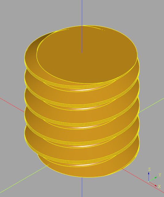
This derived class of Thread creates an external thread object as found on screws and bolts. The parameters are:
major_diameter(float)pitch(float)length(float)hand(Literal["right", "left"] = "right")hollow(bool = False) : hollow out the center of the thread object to optimize inclusion of internal detailthread_angle(Optional[float] = 60.0)simple(bool = False) : simplify thread
This class exposes instance variables for the input parameters as well as:
h_parameter(float) : the value ofhas shown in the thread diagrammin_radius(float) : inside radius of the thread diagramthread_radius(float) : thread radius of the thread diagramcq_object(cq.Solid) : cadquery Solid object
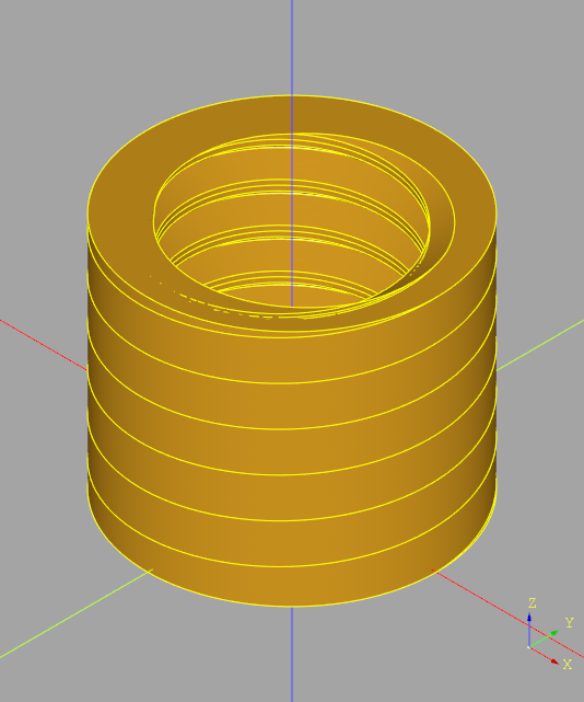
This derived class of Thread creates an internal thread object as found on nuts. This object look like a washer with the thread cut into the inside of the object such that it can be efficiently included into another object by placing it into an appropriately sized hole. The parameters are:
major_diameter(float)pitch(float)length(float)hand(Literal["right", "left"] = "right")thread_angle(Optional[float] = 60.0)simple(bool = False) : simplify thread
This class exposes instance variables for the input parameters as well as:
h_parameter(float) : the value ofhas shown in the thread diagrammin_radius(float) : inside radius of the thread diagramthread_radius(float) : thread radius of the thread diagraminternal_thread_socket_radius(float) : the outer radius of the thread object - (e.g. the size to make the hole for it to fit into)cq_object(cq.Solid) : cadquery Solid object
The fastener sub-package has been designed to be extended in the following two ways:
- Alternate Sizes - As mentioned previously, the data used to guide the creation of fastener objects is derived from
.csvfiles found in the same place as the source code. One can add to set of standard sized fasteners by inserting appropriate data into the tables. - New Fastener Types - The base/derived class structure was designed to allow the creation of new fastener types/classes. In most cases a new screw can be created by creating the new parameter
.csvfile and the new head cadquery object.
This python module provides extensions to the native cadquery code base. Hopefully future generations of cadquery will incorporate this or similar functionality.
Two additional methods are added to the Assembly class which allow easy manipulation of an Assembly like the chain cadquery objects.
Move the current assembly (without making a copy) by the specified translation vector.
Assembly.translate(self, vec: VectorLike)
    :param vec: The translation Vector or 3-tuple of floats
Rotate the current assembly (without making a copy) around the axis of rotation by the specified angle.
Assembly.rotate(self, axis: VectorLike, angle: float):
    :param axis: The axis of rotation (starting at the origin)
    :type axis: a Vector or 3-tuple of floats
    :param angle: the rotation angle, in degrees
:type angle: floatMethods to rotate a Vector about an axis and to convert a 2D point to 3D space.
Rotate a vector by an angle in degrees about x,y or z axis.
Vector.rotateX(self, angle: float) -> cq.Vector
Vector.rotateY(self, angle: float) -> cq.Vector
Vector.rotateZ(self, angle: float) -> cq.Vector
Map a 2D point on the XY plane to 3D space on the given plane at the offset.
Vector.pointToVector(self, plane: str, offset: float = 0.0) -> cq.Vector
    :param plane: A string literal of ["XY", "XZ", "YZ"] representing the plane containing the 2D points
    :type plane: str
    :param offset: The distance from the origin to the provided plane
:type offset: floatTo facilitate placement of drafting objects within a design the cadquery Vertex class has been extended with addition and subtraction methods so control points can be defined as follows:
part.faces(">Z").vertices("<Y and <X").val() + (0, 0, 15 * MM)which creates a new Vertex 15mm above one extracted from a part. One can add or subtract a cadquery Vertex, Vector or tuple of float values to a Vertex with the provided extensions.
Add a Vertex, Vector or tuple of floats to a Vertex
Vertex.__add__(
    self, other: Union[cq.Vertex, cq.Vector, Tuple[float, float, float]]
) -> cq.Vertex:
    :param other: vector to add
    :type other: Vertex, Vector or 3-tuple of float
Subtract a Vertex, Vector or tuple of floats to a Vertex
Vertex.__sub__(
    self, other: Union[cq.Vertex, cq.Vector, Tuple[float, float, float]]
) -> cq.Vertex:
    :param other: vector to add
    :type other: Vertex, Vector or 3-tuple of float
Display a Vertex
Vertex.__str__(self) -> str:Convert a Vertex to a Vector
Vertex.toVector(self) -> cq.Vector: