autoware_lidar_camera_fusion_sample
This package is for
- Example of intrinsic calibration of an RGB camera
- Example of extrinsic calibration between an RGB camera and an LiDAR
based on Autoware.AI.
Gazebo-related files are prepared to try a procedure of each calibration in Gazebo simulation.
Gazebo Environment
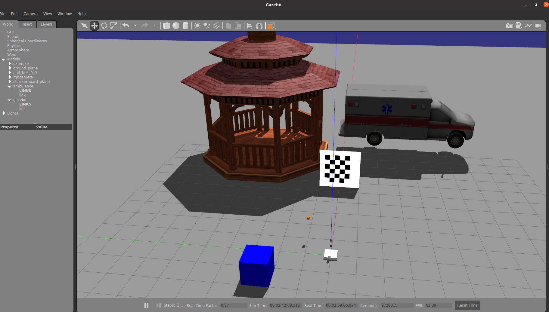
There are in the environment
- Checker board
- RGB camera(Tiny orange box)
- Velodyne(VLP-16, HDL-32).
You may insert other objects in the environment.
If you use Autoware in docker container, you can execute Gazebo simulation in your host.
To execute it, $ roslaunch autoware_lidar_camera_fusion_sample sensors.launch.
Some topics are published from gazebo simulatior and next topics are used in explanation.
- /rgb_camera/image_raw
- /rgb_camera/camera_info_nominal
- /velodyne_points2 (from HDL-32).
/rgb_camera/image_raw is raw image from orange RGB-camera.
And /rgb_camera/camera_info_nominal includes metadata of images from RGB-camera.
However, the metadata should be obtained via intrinsic calibration and published as /rgb_camera/camera_info.
You use /rgb_camera/camera_info_nominal as criteria for results of internal calibration.
Intrinsic calibration of RGB camera
To execute intrinsic calibration of RGB-camera, after executing sensors.launch, use next command.
$ rosrun autoware_camera_lidar_calibrator cameracalibrator.py --square 0.25 --size 5x4 image:=/rgb_camera/image_raw
"0.25" is the size of a edge of a square on the checkerboard, whose unit is meter. "5x4" represents the number of checker crossing. For actual calibration in real envionment, set appropriate values.
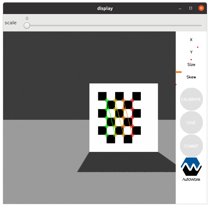
Then you rotate and move the checkerboard in gazebo simulation. As default, 40 valid images are necessary to execute intrinsic calibration. All the images should be different each other for its parameter such as position, size or skew. For efficient capturing, you set a position of the board at first and rotate it. And after you get the several images on the position, move the board and get new images.
Now, you can push a button of "CALIBRATE" which is colored by blue. Results is saved by pushing a button of "SAVE". Try to compare the results and '/rgb_camera/camera_info_nominal'.
The saved file is yaml and possible to load by calibration_publisher package
whose node publishes camera_info topic.
Extrinsic calibration between an RGB camera and a LiDAR
To execute extrinsic calibration, use next command.
$ roslaunch autoware_camera_lidar_calibrator camera_lidar_calibration.launch \
intrinsics_file:=INTRINSIC_FILE_PATH camera_id:=/rgb_camera \
target_frame:=velodyne2 camera_frame:=rgb_camera_link
In these option, "INTRINCSIC_FILE_PATH" is file path of the result of intrinsic calibration. "camera_id" is namespace of camera-related topics. For example, "/rgb_camera/image_raw", "/rgb_camera/camera_info", "/rgb_camera/image_rectified" and so on are used as topics' names. "target_frame" is frame_id of point clouds from LiDAR. And "rgb_camera_link" is frame_id of image from RGB-camera. Please check argument of the launch file.
The launch file executes below nodes with namespace.
- /rgb_camera/calibration_publisher
- /rgb_camera/rectifier
- /rgb_camera/image_view2
- /rgb_camera/autoware_camera_lidar_calibration_node
"calibration_publisher" node publishes "camera_info" topic by loading an intrinsic calibration file. "rectifier" node subscribes "image_raw" and "camera_info" topics and publishes "image_rectified" topic. The "calibration_publisher" node can broadcast TF between LiDAR and RGB-camera, however it is disabled here.
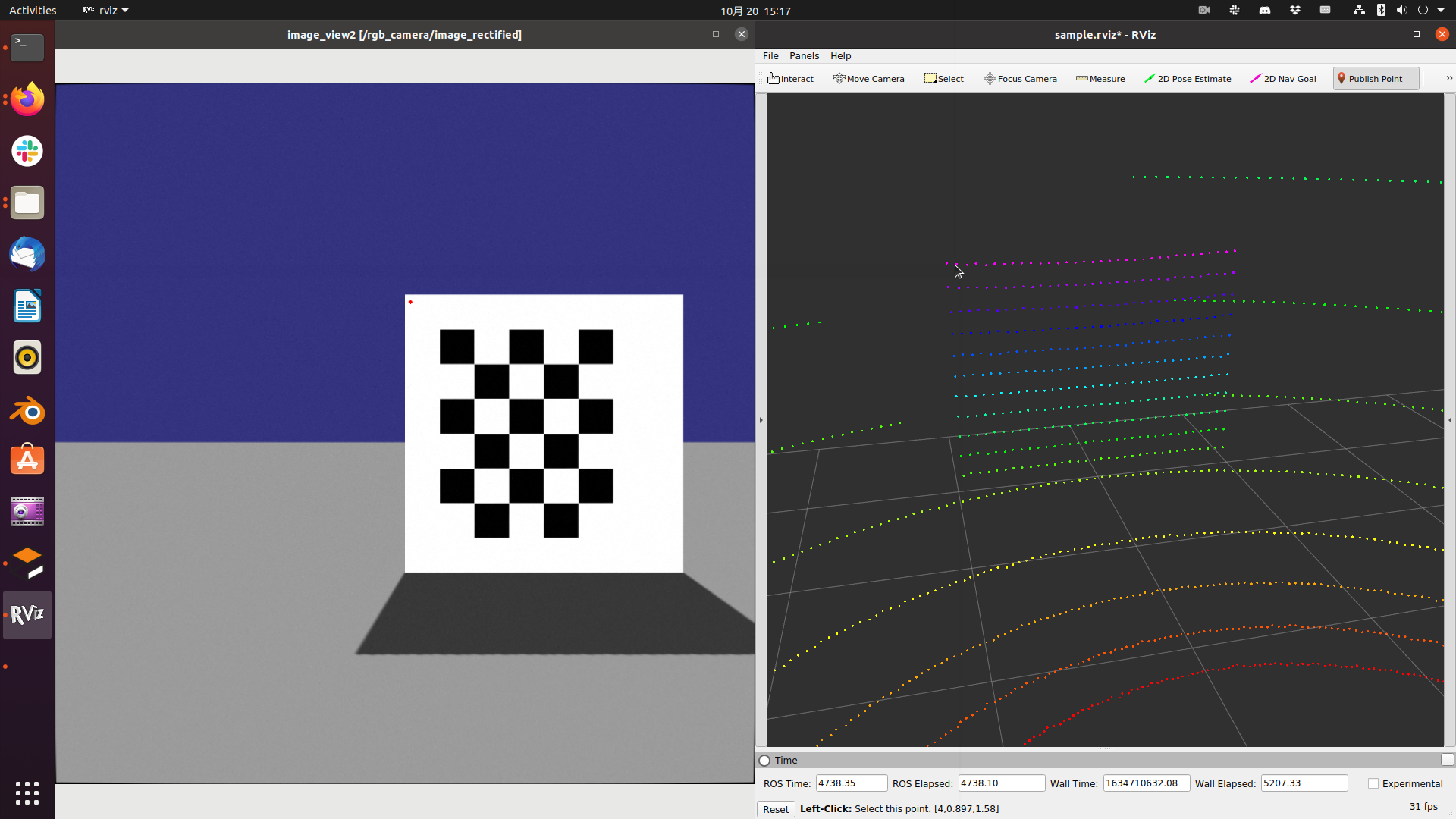
And "image_view2" shows "image_rectified" and make user click on the image. The clicked point is published as "image_rectified/screenpoint" topic.
"autoware_camera_lidar_calibration_node" node subscribes "image_recrified/screenpoint" topic from "image_view2" and "clicked_point" topic from RViz(Publish Point). The node compares points on image and on point clouds, then calculates extrinsic calibration.
Click a point on the checker board on "image_view2" and the same point of point cloud on RViz by using "Publish Point". In RViz, you need to set Global options/Fixed frame to lidar frame_id; "velodyne2". And, Lidar axis should be as follows.
- X axis points to the front of lidar
- Y axis points to the left
- Z axis points upwards
You can read on terminal the output from "autoware_camera_lidar_calibration_node" for example...
......

Number of points: 0:1
[3.98635, 0.897378, 1.5837]

Number of points: 1:1

......
The right number represents clicks on RGB image, and the left number does clicks on point cloud. Nine pairs are necessary to calculate extrinsic calibration, and both numbers should be same. You need to carefully clink on RGB-image and point clouds. After gathering the pairs, extrinsic calibration is executed and the result is saved.
The result's form is same to the one of intrinsic calibration. However, contents of "CameraExtrinsicMat" are filled by Transformation matrix(4x4) from Lidar to Camera. You should check the result is consistent and may fix it.
Calibration_publisher and Pixel-Cloud fusion
To utilize the result of intrinsic and extrinsic calibration, use "calibration_publisher" package.
$ rosrun calibration_publisher calibration_publisher _calibraion_file:=EXTRINSIC_FILE_PATH _camera_frame:=rgb_camera_link _target_frame:=velodyne2 image_topic_src:=/rgb_camera/image_raw _camera_info_topic:=/rgb_camera/camera_info
You can check connection of TF between camera_frame and target_frame in RViz.
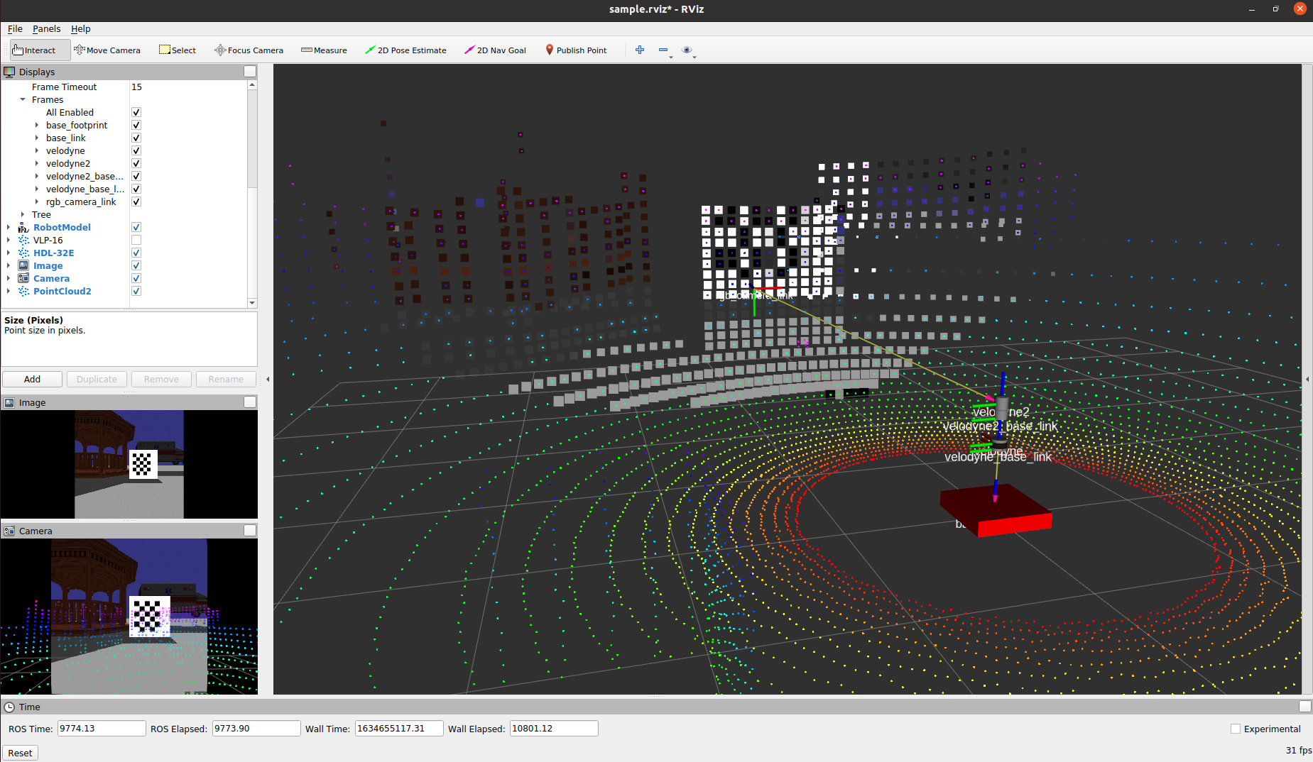
In order to superpose RGB pixel color on points from LiDAR, you can use "pixel_cloud_fusion" package. The "pixel_cloud_fusion" packages requires recrified image, hence "image_processor" package of Autoware is also executed as following.
$ rosrun image_processor image_rectifier _image_src:=/rgb_camera/image_raw _camera_info_src:=/rgb_camera/camera_info /image_rectified:=/rgb_camera/image_rectified
$ roslaunch pixel_cloud_fusion pixel_cloud_fusion.launch points_src:=/velodyne_points2 image_src:=/rgb_camera/image_rectified camera_info_src:=/rgb_camera/camera_info
Below image shows the superposing of pixel on point cloud. The results represents that the external calibration generates slightly different transformation. You may fix the transformation between camera and LiDAR with checking the superpositing.


