- Introduction
- Simulation Environment Settings
- Reproducing Scatter Plots
- Reproducing BER Diagrams
- Binary Phase-Shift Keying Modulation (BPSK)
- Quadrature Phase-Shift Keying Modulation (QPSK)
- Frequency Shift Keying (FSK)
- Quadrature Amplitude Modulation (QAM)
Simulating the performance of different modulation schemes, such as, BPSK, QPSK, FSK, QAM in an Additive White Gaussian Noise, AWGN environment.
- The simulation is done using 2 different parameter sets for the Random Input Generator defined below.
- Set 0: Sample Time = 0.1 s, Samples Per Frame = 100
- Set 1: Sample Time = 1 s, Samples Per Frame = 100
- The noise level is set to 10 dB.
- The simulation period is set to 100.
- Integer Random Generator seed is set to Auto.
- Noise initial random seed is set to 67.
- All scatter plots are produced at a noise level (Eb/No) of 10 dB.
- All BER diagrams use a noise level of [-10, 10] dB.
- The simulation period is set to 100.
To reproduce the scatter plots, kindly do the following:
- Set the simulation parameters as mentioned in the Simulation Environment Settings, it will most likely be already set, except for the Random Input Generator parameter sets.
- Double click the AWGN channel, and set the noise level (Eb/No) to 10 dB.
- Set the simulation time to 100 and click run.
To reproduce the BER diagrams, kindly do the following:
- Set the simulation parameters as mentioned in the Simulation Environment Settings, it will most likely be already set, except for the Random Input Generator parameter sets.
- Double click the AWGN channel, and set the noise level (Eb/No) to variable called
EbNo. - From Matlab's command line, run the BER diagram tool using the command
bertool. - From the
Theoreticaltab in the BER tool window, set the following:- Eb/No range to -10:10.
- Channel type to AWGN.
- The respective Modulation type and order.
- Click
Runto plot the theoretical exact BER diagram. - From the
Monte Carlotab in the BER diagram tool, set the following:- Eb/No range to -10:10.
- Simulink model to the path of the respective file for each modulation scheme.
- Set the BER vairable name to
BER. - Set the simulation limits as desired. Left as default (Number of erros = 100, number of bits = 1e8).
- Click
Runto plot the Monte Carlo BER diagram.
BPSK is a two phase modulation scheme, where the 0’s and 1’s in a binary message are represented by two different phase states in the carrier signal: theta = 0 for binary 1 and theta = 180 for binary 0.
- Random Generator set size = 2
- Phase offset (rad) = 0

-
Parameter Set 0:

-
Parameter Set 1:

-
Parameter Set 0:

-
Parameter Set 1:

-
Simulation 0 (green) is using parameter set 0.
-
Simulation 1 (red) is using parameter set 1.

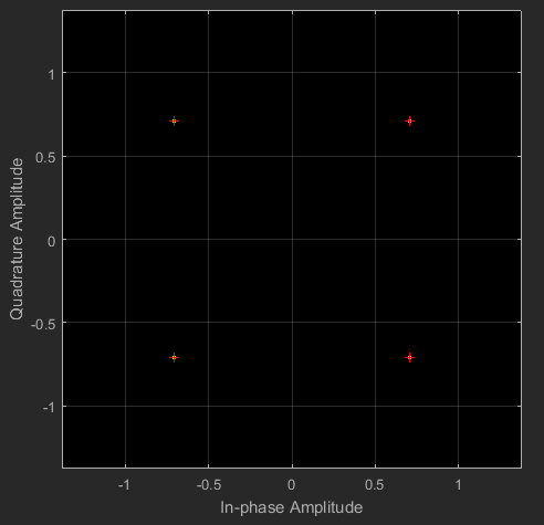
QPSK is a form of Phase Shift Keying in which two bits are modulated at once, selecting one of four possible carrier phase shifts (0, 90, 180, 270). QPSK allows the signal to carry twice as much information as ordinary PSK using the same bandwidth.
- Random Generator set size = 4
- Phase offset (rad) = pi/4

-
Parameter Set 0:

-
Parameter Set 1:

-
Parameter Set 0:

-
Parameter Set 1:

-
Simulation 0 (green) is using parameter set 0.
-
Simulation 1 (red) is using parameter set 1.

FSK is the frequency modulation system in which digital information is transmitted through the discrete frequency change of a carrier wave. The simplest FSK is binary FSK (BFSK).
- Random Generator set size = 2
- M-ary number = 2
- Frequency separation = 6 Hz
- Samples per symbol = 17

-
Parameter Set 0:

-
Parameter Set 1:

-
Parameter Set 0:

-
Parameter Set 1:

-
Simulation 0 (green) is using parameter set 0.
-
Simulation 1 (red) is using parameter set 1.

QAM is a signal in which two carriers shifted in phase by 90 degrees (i.e. sin and cos) are modulated and combined. As a result of their 90 phase difference they are in quadrature and this gives rise to the name. Often one signal is called the In-phase or I signal, and the other is the quadrature or Q signal.
- QAM 16
- QAM 64
- Random Generator set size = 16, 64
- M-ary number = 16, 64
- Normalization method = Average Power
- Phase offset (rad) = 0
- Average power referenced to 1 Ohm = 1 Watts
-
QAM 16

-
QAM 64

- QAM 16:
-
Parameter Set 0

-
Parameter Set 1

-
- QAM 64
-
Parameter Set 0

-
Parameter Set 1

-
- QAM 16:
-
Parameter Set 0

-
Parameter Set 1

-
- QAM 64
-
Parameter Set 0

-
Parameter Set 1

-
-
Simulation 0 (green) is using parameter set 0.
-
Simulation 1 (red) is using parameter set 1.
-
QAM 16

-
QAM 64

-