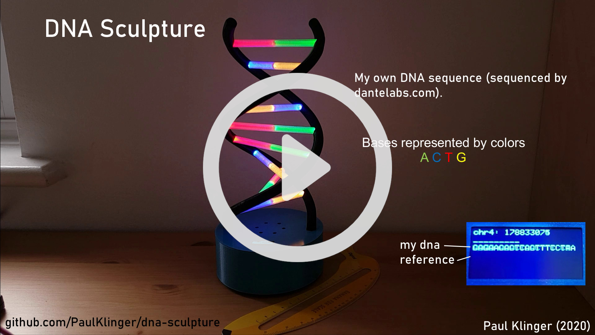
There are some in-progress photos of the build here.
I had my DNA sequenced by dantelabs.com (the 30X whole genome sequencing). They provide fastq, aligned bam, and vcf files, but just to understand some more about the process I redid the alignment with bwa and the variant calling with bcftools. (There are some issues with the called variants, see comments in dna.py, but that doesn't really matter for this project.) I've released all my genome files as creative commons: VCF, BAM (34 GiB!), BAI.
The 3D printed parts were printed on my Prusa MK3S 3d printer.
The helices need quite a lot of support material, so the surface finish wasn't great. I removed the worst of it with some 300 grit sandpaper and then used a heat gun to smooth the surface.
The two parts of the case are held together with three m2 screws that screw into heat-set metal inserts in the top plate. The PCBs are retained with m2 screws into metal inserts in the bottom plate. The helices are friction fit into the top part of the case and secured with an m2 screw that screws into the plastic.
The base pairs between the two helices are printed in transparent PLA and the holes are filled with short pieces of 4mm PMMA side-glow fiberoptic. I glued a bit of aluminium foil to the end of the fiberoptic (where the two pieces meet in the middle) so the colors of the complementary bases don't mix. The base pairs are just friction fit into the helices, and the LEDs are sort-of retained by the little tabs at the end of the bases, although most of them broke off during assembly.
The electronics are very simple, just a raspberry pi zero w, 18 WS2812B RGB LEDS in two strings of nine, a momentary button (for turning it on/off) and a diode (necessary for the button due to overlapping pin functions, see below). The LEDS are connected with some 30 AWG wire, soldered directly to them. I assembled the LEDs already inside the two helices, adding one and then pulling the cables through to the next hole. That's absolutely horrible work, I'm pretty amazed it works at all. When putting the connecting transparent parts in they put pressure on the LEDs and it's quite likely that some of the connection fail and you have to fix it in place... Theoretically the WS2812B require an external capacitor (except for the new v5 version) but that would make assembly even more horrible. Thankfully it works fine without them. The second PCB just contains a micro usb connector and a big capacitor, I used the same PCB as for my satellite tracker.
The default I2C baudrate of the raspberry pi zero w is quite low, which limits the display to ~2 fps. Adding
dtparam=i2c_arm=on
dtparam=i2c1=on
dtparam=i2c1_baudrate=800000
to boot.config fixes this.
Getting both a single button for startup/shutdown and I2C (for the display) to work is a bit harder than it should be. When the RPi is shut down ("halt" state) it can only be woken up by connecting pin 3 (BCM numbering) to ground (or disconnecting and reconnecting power). But pin 3 is also the clock pin for the standard I2C port (i2c-1). Theoretically there's a second I2C, i2c-0 on pins 0/1 but I didn't manage to increase the baudrate for that. (Theoretically this should be possible using "dtparam=i2c_vc=on" to enable it and "dtparam=i2c_vc_baudrate=800000" to set the baudrate, but for me it stayed at the default (low) speed.)
The solution I found is by Christian U. on stackexchange (thanks!). He suggests connecting a diode from pin 3 to another GPIO (pin 4 in my case) and the button between pin 4 and ground. That way when the Pi is off it can be turned on by pushing the button (as current can flow from pin 3 to pin 4) but when the I2C peripheral pulls the clock line low this doesn't affect pin 4. When the button is pressed pin 4 is pulled low which triggers the shutdown (I'm using the gpiozero library for button handling). Pushing the button also pulls pin 3 low, so this messes up the I2C interface, but as the device is shutting down anyway this doesn't matter.
To make sure that the Pi wakes up when the button is pressed the forward voltage of the diode must be small enough. I tried a red LED but that didn't work, so I'm using an SS24 power diode now (the only other kind of diode I had at hand).
The code here is not very nice, and it's pretty slow, mostly because of the display library. But it's just fast enough for ~10 updates per second, which is about the limit of what is nice to look at anyway.
The file dna.service is the systemd service configuration used to start main.py on startup (mostly as a syntax reminder to myself).
