![]()
"IoT Made Easy!"
Devices: | PIC32CXBZ2 | WBZ45x |
Features: | CAN | BLE |
THE SOFTWARE ARE PROVIDED "AS IS" AND GIVE A PATH FOR SELF-SUPPORT AND SELF-MAINTENANCE. This repository contains example code intended to help accelerate client product development.
For additional Microchip repos, see: https://github.com/Microchip-MPLAB-Harmony
Checkout the Technical support portal to access our knowledge base, community forums or submit support ticket requests.
- Introduction
- Bill of materials
- Hardware Setup
- Software Setup
- Harmony MCC Configuration
- Board Programming
- Run the demo
This application serves as an illustration of how to extend a CAN network wirelessly using BLE.
 The CAN-BLE Central Device connects to the CAN-BLE Peripheral Device and establishes a BLE link using Microchip's proprietary Transparent UART Profile for data transfer.
The Microchip CAN Bus Analyzer tool is used in this example to simulate transmitting and receiving CAN messages from a CAN network. Alternatively, the CAN-BLE peripheral device can be connected to a mobile application to visualize the CAN messages on a mobile phone.
| TOOLS | QUANTITY |
|---|---|
| PIC32CX-BZ2 and WBZ451 Curiosity Development Board | 2 |
| MCP251863 CLICK | 2 |
| CAN BUS ANALYZER TOOL | 2 |
| DB9 Connector | 2 |
| WBZ451 | MCP251863 CLICK | Description | WBZ451 | MCP251863 CLICK | Description | |
|---|---|---|---|---|---|---|
| AN | 1(STB) | StandBy Control | PWM | NC | NC | |
| RST | 13(IN1) | RX Interrupt | INT | NC | NC | |
| CS | 3(CS) | CHIP SELECT | RX | NC | NC | |
| SCK | 4(SCK) | SPI CLOCK | TX | NC | NC | |
| MISO | 5(MISO) | SERIAL DATA OUTPUT | SCL | NC | NC | |
| MOSI | 6(MOSI) | SERIAL DATA INPUT | SDA | NC | NC | |
| 3.3V | 7(3.3V) | POWER SUPPLY | 5V | 5V | 5V POWER SUPPLY | |
| GND | 8 (GND) | GROUND | GND | GND | GROUND |

-
- Version: 6.05
- XC32 Compiler v4.10
- MPLAB® Code Configurator v5.2.1
- PIC32CX-BZ_DFP v1.0.107
- MCC Harmony
- csp version: v3.14.0
- core version: v3.11.1
- CMSIS-FreeRTOS: v10.4.6
- wireless_pic32cxbz_wbz: v1.1.0
- dev_packs: v3.14.0
- wolfssl version: v4.7.0
- crypto version: v3.7.6
- wireless_ble: v1.0.0
-
[Microchip CAN BUS Analyzer V2.3] (https://ww1.microchip.com/downloads/en/DeviceDoc/Microchip%20CAN%20BUS%20Analyzer%20v2.3%20Installer.zip)
-
Any Serial Terminal application like TERA TERM terminal application
-
CAN-BLE Central Device
Refer the documentation available in 01_wbz451_mcp251863_CAN_BLE_Central
-
CAN-BLE Peripheral Device
Refer the documentation available in 02_wbz451_mcp251863_CAN_BLE_Peripheral
- The Precompiled hex file is given in the hex folder. Follow the steps provided in the link to program the precompiled hex file using MPLABX IPE to program the pre-compiled hex image.
The application folder can be found by navigating to the following path:
- CAN-BLE Central Device
- "01_wbz451_mcp251863_CAN_BLE_Central\firmware\bleCan_Central.X"
- CAN-BLE Peripheral Device
- "02_wbz451_mcp251863_CAN_BLE_Peripheral\firmware\bleCan_Peripheral.X"
Follow the steps provided in the link to Build and program the application.
- Program a WBZ451 Curiosity board with bleCan_Central application and other with WBZ451 Curiosity board with bleCan_Peripheralapplication.
- Connect MCP251863 CLICK to Mikroe Header in WBZ451 Curiosity board as per the Hardware Setup
- Connect CAN BUS ANALYZER TOOL to MCP251863 CLICK board using a DB9 Connector as shown in the figure.

- The transmission and receipt of CAN messages from a CAN network are recreated using the Microchip CAN Bus Analyzer tool.
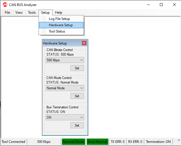
- Open Microchip CAN Bus Analyzer tool, in 'Setup --> Hardware Setup', Configure the CAN Bitrate Control, CAN Mode Control and Bus Termination Control as shown below figure.
- Open Rolling Trace window from 'Tools --> Rolling Trace' to view the transmitted and received data.
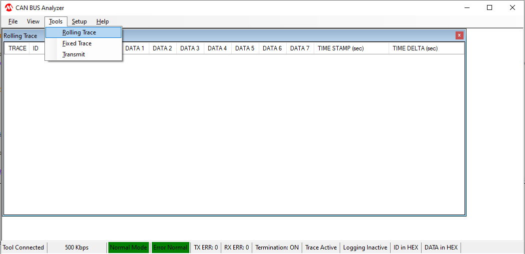
- Open Transmit Window from 'Tools --> Transmit' to transmit data from CAN Bus Analyzer Tool.
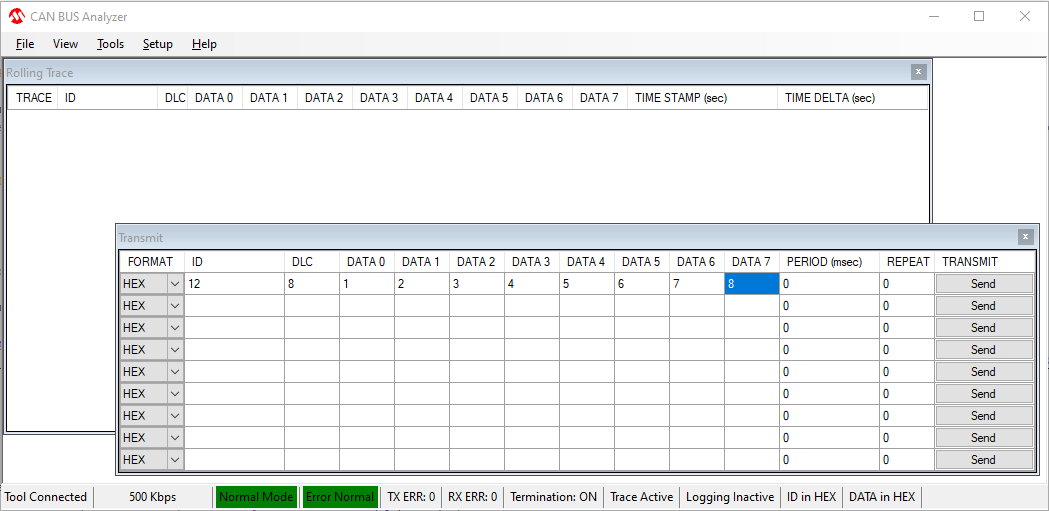
- Configure the Transmit window as shown in the below figure.
- Similarly Open another instance of Microchip CAN Bus Analyzer tool and configure the tool as mentioned in above steps
- Click on Send Button in Transmit window to send the data from CAN
- Observe the data is being received on other instance of CAN Analyzer
- The below video shows the working of the CAN-BLE bridge.


- Program a WBZ451 Curiosity board with bleCan_Peripheralapplication.
- Connect MCP251863 CLICK to Mikroe Header in WBZ451 Curiosity board as per the Hardware Setup
- Connect CAN BUS ANALYZER TOOL to MCP251863 CLICK board using a DB9 Connector as shown in the figure.
- Open Microchip MBD Application on Mobile phone and click on BLE Smart to scan for the available devices.

- The MBD App will scan for the available devices and the scan result will be shown as below. Select "CAN BLE Bridge Device" from the scan list.

- Click on the Connect button to establish a BLE Connection with the device.

- Once BLE Connection is established and service discovery is completed, Transparent UART Service is discovered and shown as Microchip Data Service as shown below.

- To view the CAN messages transmitted via BLE, select the Transparent UART TX Characteristic (UUID ending with 9616) as shown below.

- In the Characteristics page, enable notify/indicate as shown below.

- Open CAN Bus Analyzer Tool and set Transmit window as shown below and click on the send button.

- The MBD App will show the received messages as shown below.

- The below video shows the working of the CAN-BLE bridge using MBD application.
