Parallel cryo electron tomography (PACE-tomo) is a set of SerialEM scripts written in Python that allows for the collection of an arbitrary number of tilt series in parallel via beam image shift. Please refer to the publication for more details.

PACE-tomo has been tested on a JEOL JEM-F200 and a Thermo Fisher Scientific Krios G3i and G4 transmission electron microscope using the dedicated computer for the Gatan K2 or K3 direct electron detector. The open-source microscope control software SerialEM should be installed and calibrated.
PACE-tomo does not require the installation of any stand-alone software. However, it does require SerialEM 4.1 or higher capable of running Python scripts.
You can run the following lines of code in a SerialEM script window to test if Python is configured correctly:
#!Python
import serialem as sem
sem.OKBox("Python works!")
If you get an error message, please consult the SerialEM website on how to setup Python for SerialEM.
Additionally, you require the numpy, scipy and matplotlib modules for Python. Depending on your Python installation the following commands in the Windows Command Prompt should take care of it (you will need network connection):
pip install numpy
pip install scipy
pip install matplotlib
To check if SerialEM has access to the modules, run this script inside a SerialEM script window:
#!Python
import serialem as sem
import numpy as np
from scipy import optimize
import matplotlib.pyplot as plt
sem.OKBox("All necessary modules are installed!")
To use PACE-tomo just copy the content of PACEtomo.py and PACEtomo_selectTargets.py as well as any auxiliary scripts you want to use in an empty SerialEM script slot each.
For optimal results, load the sample such that the lamellae are oriented with the milling direction perpendicular to the tilt axis (schematic for a Krios autoloader). Set up SerialEM low dose mode like you would for conventional tilt series acquisition. Make sure buffer O is outside the range of Roll Buffers (Buffer controls window). Offsets for Focus and Trial areas can be set to 0 to preserve specimen area. Make sure to set the appropriate tilt axis offset (more details below). It is recommended to do a coma-free alignment and a coma vs image shift calibration to minimise beam tilt for large image shifts (you might need a carbon film to get nice power spectra for CTF fitting). However, in most cases beam tilt will not be resolution limiting.
Before you run a PACE-tomo acquisition, you must define the targets using the PACEtomo_selectTargets script.
Caution: To avoid problems with the SerialEM working directory, please choose the folder in which you save your frames during acquisition before running the selectTargets script.
Inside the script, there are several settings you can adjust before you start. If you set guidance to True, message boxes will guide you through the target selection procedure. Once you are familiar enough with the steps, you can set guidance to False which should streamline the setup.
When picking targets in close proximity, it is useful to keep the illuminated area in mind as the stage is tilting. Set drawBeam to True to show an approximation of the exposure on your sample around selected targets. You can set a fixed beamDiameter or set it to 0 to use the IlluminatedArea value on Thermo Fisher microscopes. You can also adjust the simulated stretching of the beam for a tilted sample using the maxTilt value.
In general, there are 3 ways to define targets:
-
Manually: Selecting targets by dragging the image and centring features of interest.
- By default the script will use View mode to find targets. If you set useSearch to True, it will use Search mode instead.
- Set targetByShift and targetPattern to False.
- If you want to choose your targets freely, just proceed with the next step. Alternatively, you can use a group of points as template for target selection:
- Use Add Points in the Navigator to select points on a montage or a low magnification image.
- Select the first point of the group and run the script as described below.
- Move the stage to your first target (tracking target), which should have enough contrast to be tracked confidently.
- In the SerialEM UI in the Image Alignments & Focus window, uncheck Move stage for big mouse shifts.
- Run the script from the script window.
- Choose the folder where all files related to PACE-tomo including the final tilt series are saved. This should be the same folder for all PACE-tomo acquisition areas if you plan to run them in batch via Acquire at items!
- Choose a rootname for the current acquisition area. All files related with this acquisition area will be named accordingly.
- The script will guide you step-by-step through the following process via message boxes:
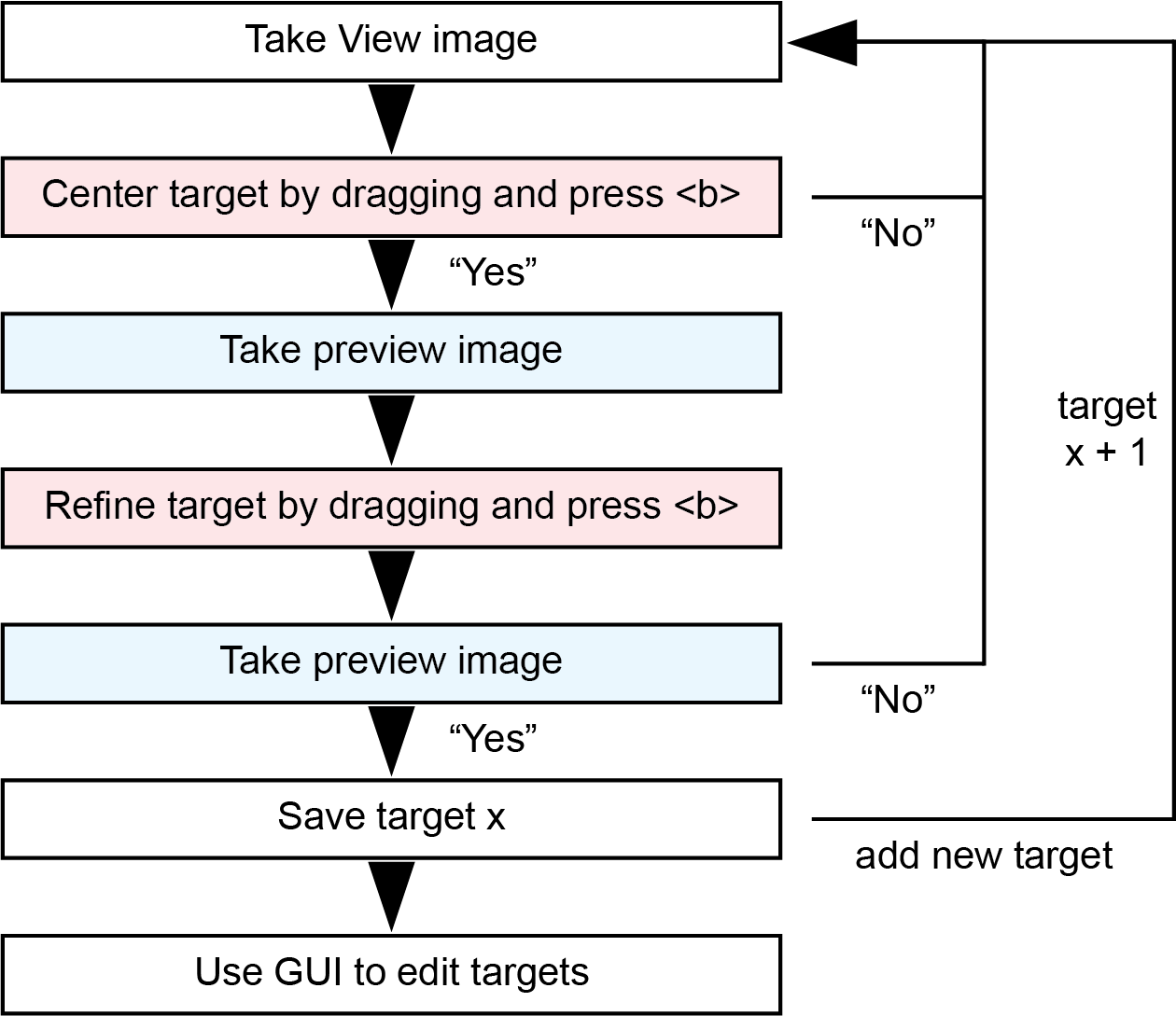
- When dragging the image, make sure not to hit the "Shift" key as this will trigger stage movement.
- When you do not add any more targets, the script will open a GUI window with an overview over all selected targets.
-
Fixed shifts: Selecting targets by specifying relative image shifts in specimen coordinates.
- The overall process is like 1., but instead of dragging to centre a target, you supply shifts in µm for X and Y that are applied from the current position to reach the next target. This is useful for (semi-)ordered patterns of targets.
- Set targetByShift to True. Set targetPattern to False.
- Move the stage to your first target (tracking target).
- Run the script from the script window.
- The script will guide you through the process.
-
Pattern: Selecting a target pattern that can be applied to arbitrary stage positions.
- A target pattern is useful for the collection on regular holey support films and can be easily transferred to other stage positions.
- Set targetPattern to True.
- If you have a hole reference saved in buffer P and want to refine the grid vectors automatically according to hole positions, set alignToP to True.
- Set size to the appropriate value n for your desired pattern (2n+1)x(2n+1), e.g. 2 for a 5x5 pattern.
- The procedure to determine the specimen shift between holes is integrated in the script:
- Before running the script, roughly centre your central hole.
- The script will align the hole using the reference in buffer P.
- You will be asked to drag with the right mouse button to centre the neighbouring hole of the grid.
- The script will then automatically find the vectors of the grid using the reference in buffer P.
- The script will determine the coordinates of all targets and open the GUI for target editing.

All targets are saved in the navigator and a rootname_tgts.txt file is created. Target 1 is set to Acquire and the name of the rootname_tgts.txt file is saved in its Note entry.
Once target selection is completed a GUI will open showing a schematic of your targets and some additional information. This GUI will also open if you select a navigator item with an already associated target file and run the target selection script. It allows you to view, edit, add targets and specify settings for acquisition.

The main components are a list of all targets with associated file names, image shifts and skip flag, and a plot of all targets with the origin at the tracking target.
You can select targets by left clicking them in the list or in the plot. Right clicking targets in the plot toggles their skip flag. While you cannot delete targets, setting skip to True ensures they will be ignored during acquisition.
Make Track can be used to make the selected target the tracking target instead. This requires some realignment and hence, additional Preview exposures on the new tracking target. Use with caution!
Load Map prompts you to enter a navigator label and will load the associated map in SerialEM. This is useful when you want to load a montage to get an overview over your target area.
Add Targets will realign to your tracking target and re-enter the target selection loop.
Save Views will take a View image at every target position and save it as a map. It will also save a JPG snapshot of the map with all navigator items marked. This might be useful to revisit the wider context of a tomogram after reconstruction. In the future, these view images containing centred targets could be potentially used to train a neural network for automated picking of target regions.
Reorder will read the current order of targets displayed in the list. You can change the order by dragging and dropping.
Copy to Acq is only accessible when targetPattern was used for target selection. It will copy the target file for all points in the navigator that have been set to acquire (excluding points already associated with a target file).
Save will save all changes to the target file. Reset will reset changes made since the GUI was opened (except changes to the tracking area).
Settings can be saved in the targets file and overwrite values given in the PACEtomo.py script.
Another feature of the GUI is the Measure geometry procedure. This automates the estimation of pretilt and rotation on your sample similar to the PACEtomo_measureGeometry.py script. Basically, it measures the defocus at >3 points on the sample and fits a plane to estimate values for pretilt and rotation. You can select these points directly on the plot using the middle mouse button. Make sure to avoid targets to prevent additional exposures of areas of interest. Ideally, five or more points should be spread evenly across the sample area while dark spots, ice chunks and holes are avoided. You can reset the point selection using the Reset geo pts button and once you selected your points you can press Measure geometry. The estimated pretilt and rotation will be filled into the associated text fields, but you still have to save them to the targets file.
For targetPattern selections geo points are automatically suggested. However, geometry values might not be applicable if you plan to use the pattern on different stage positions. For that purpose, the PACEtomo.py script has an automated routine using the suggested points to measure the geometry at every stage position before starting the acquisition (more details below).
In the bottom left you can find the controls for the plot. These are purely visual and some of them cause problems with the beam diameter visualization.
On the right, you can find Toggle beam to show or hide the beam diameter visualization, and buttons to swap or mirror the axes to make the plot fit your SerialEM view.
If you made any changes, please don't forget to click Save. Once you are done you can close the window and a message box will tell you the number of selected targets.
Caution: Only target 1 of each PACE-tomo acquisition area should be set to Acquire!
PACE-tomo runs a dose-symmetric tilt scheme with groups of 2 tilt images per branch in all cases. Before starting the PACE-tomo collection, please check the settings inside the PACEtomo.py script. Most settings are self-explanatory, but here is a more detailed description for some of them:
- The startTilt in degrees is usually 0 or, in case of a lamella, the compensating tilt for the pretilt (in case of a pretilt of -10 degrees, a startTilt of 10 degrees can be used). The startTilt has to be divisible by the tilt step.
- The tilt range is given by the absolute minTilt, maxTilt and step values in degree. The tilt series branches do not have to be symmetrical.
- If a defocus range is given, PACE-tomo will use different target defoci (separated by stepDefocus) for each target. If you want to use the same target defocus, keep minDefocus and maxDefocus the same.
- If your tilt axis offset is not appropriately set, there will be a pseudo-linear defocus slope throughout your tilt series. You can run PACE-tomo on a carbon film, estimate the defocus by CTF fitting and plot the change in µm per degree. Set this value as focusSlope to compensate in subsequent acquisitions. Alternatively, refine the tilt axis offset to minimise the slope. When using SerialEM’s fine eucentricity routine to obtain a tilt axis offset, a significant focus slope remains. You can use the PACEtomo_measureOffset.py script to get a PACE-tomo optimised estimate for the tilt axis offset.
- You can set delays to be applied after adjusting the image shift and after tilting. On modern state-of-the-art microscopes and resolutions typical of subtomogram averaging, such delays should not be necessary.
- zeroExpTime can be a custom exposure time in seconds for the first tilt image. This can be useful for hybrid processing approaches. When set to 0 the same exposure time will be used for all tilt angles.
- trackExpTime allows for a custom exposure time used only for the tracking tilt series. When set to 0 the same exposure time will be used for all tilt series.
- trackDefocus allows for a custom defocus value used only for the tracking tilt series. When set to 0 the same defocus range will be used for all tilt series.
Geometry settings:
- The pretilt of the lamella (if applicable) is determined during the focused ion beam milling process and is usually between 8-12 degrees. The sign is important and depends on the orientation in which the grid was loaded into the microscope. For example, in case of a FIB milling angle of 10 degrees: If the lamella appears thinner/brighter at +10 degrees stage tilt angle, the pretilt value should be -10 degrees and vice versa. (It is recommended to load lamella containing grids consistently in the same orientation.) You can use the PACEtomo_measureGeometry.py script to get an estimate of your lamella (or holey support) geometry.
- Lamellae should be oriented with the milling direction perpendicular to the tilt axis during sample loading. In this case the rotation should be 0 degrees. If there is a residual rotation you can estimate and enter it for the initial estimation of the eucentric offset. Again, the sign depends on the orientation of the lamella in the microscope.
Holey support settings:
- If you want to use PACE-tomo on a regular target pattern (e.g., holey support film), set tgtPattern to True. Additionally, set alignToP to True if you saved a hole template to buffer P to use for target alignment.
- If refineVec is set to True, PACE-tomo uses the template in buffer P to refine the grid vectors of the target pattern at the current position. The grid of holes can vary slightly from grid square to grid square, which can become problematic for large target patterns (7x7 or larger).
- measureGeo set to True will cause the script to automatically determine five points between the targets to measure the defocus and estimate the pretilt and rotation values of the sample support similar to the PACEtomo_measureGeometry.py script. This can be useful for bent sample supports exhibiting varying geometries from grid square to grid square. It should be avoided if the pattern is tight and additional exposures within the grid would overlap with target positions.
Session settings:
- beamTiltComp should be set to True if you did the coma vs image shift calibration.
- By setting addAF to True you can add additional autofocus routines on target 1 at every branch switch of the dose-symmetric tilt series. This should help keeping the defocus spread low at the cost of overexposing the tracking tilt series.
- previewAli can be set to True if you want to align every target to its saved Preview image. This helps to keep your target centred if your startTilt is not 0. If your field of view is large and your feature of choice does not have to be centred precisely, previewAli can be set to False to reduce the initial dose on your targets. previewAli can also be used for a “targetPattern” if the grid is not very regular and vectors alone are not precise enough. In this case you should also have alignToP set to True.
- If geoRefine is set to True, PACE-tomo will try to refine the sample geometry model after the first Record image of every target was taken. It will use the defoci determined by CTF estimation to fit a plane or paraboloid and overwrite the previously determined geometry estimation. This is useful for large target patterns (7x7 or larger) on bent or wavy support film. More settings for geoRefine are mentioned below.
Advanced settings:
- CTF estimation is done for every Record image and the defocus is written to the .mdoc file. CTFfind is integrated in SerialEM and is used when doCtfFind is set to True. It is fast, but not very reliable especially at higher tilt angles. IMOD's ctfplotter is more robust and now also integrated in SerialEM. You can use it by setting doCtfPlotter to True. Currently, CTF estimation is only used for geoRefine.
- If you use geoRefine, fitLimit is the resolution cut-off beyond which CTF estimates will not be considered for the geometry refinement routine. parabolTh is the minimum threshold of available CTF estimates to fit a paraboloid instead of a plane.
- SerialEM has a hard limit on applying image shifts, which is 15 µm by default. imageShiftLimit will overwrite this SerialEM property. The maximum amount of image shift is system dependent and the limit for Thermo Scientific TEM systems is always somewhere below 25 µm.
- The number of dataPoints used for the calculation of the eucentric offset of each target was kept at 4 throughout all experiments. Changes could be beneficial to performance.
- The alignLimit should keep the cross-correlation alignment in check in cases of low contrast. On good stages the alignment error should never be worse than 0.5 µm.
- If you set minCounts greater than 0, a branch of a target can be terminated independently if the image mean counts were below the threshold. The counts are considered per second of exposure and the ReportExposure command in SerialEM 4.0+ is used to obtain the exposure time.
- ignoreFirstNegShift usually improves the alignment of the first tilt images from the negative branch and should generally be set to True.
- slowTilt should only be set to True if you need additional tilt backlash corrections for the positive tilt branch, which should not be necessary for good stages.
- taOffsetPos and taOffsetNeg allow you to apply additional tilt axis offsets for positive and negative branches, respectively (as used for the side-entry holder dataset in the manuscript). These offsets are applied on top of the global offset set in SerialEM and are only used for the internal calculations.
Any numerical setting in the script can be overwritten by settings in the target file (rootname_tgts.txt). This allows for varying settings during batch acquisition of several PACE-tomo areas. To overwrite a setting add a line like _set varName = numericalValue at the beginning or end of the targets file.
You can run the PACE-tomo acquisition script either by selecting the entry of target 1 in the Navigator (its Note entry contains rootname_tgts.txt) and pressing Run in the script window or you can run it in batch via the Acquire at Items... dialogue.
In case you want to run PACE-tomo on a regular grid targetPattern, you can set all desired tracking stage positions to Acquire in the navigator and run the PACEtomo_selectTargets.py script on the original navigator item. Within the GUI, you can click Copy to Acq to copy the target file to all marked points. Alternatively, you can copy the targets file manually and edit the Note entry of all target positions to contain the target file name.
All files are created in the folder you specified during target selection. Target images have the suffix tgt_xxx and collected tilt series have been saved with the suffix ts_xxx and their accompanying .mdoc file. Additionally, a rootname_tgts_runXX.txt is created containing all information to restart an acquisition after it was aborted or crashed. The .log file is saved for every PACE-tomo run independently.
In case a PACE-tomo run crashes or is aborted, you can attempt to recover and resume the acquisition. Run the PACEtomo.py script on the same navigator item and if a run file is present, it will ask you if you want to recover the run. Recovery will likely not track as accurately as a continuous run for the first few images. Especially if time passed or the stage was moved between crash and recovery attempt.
If you feel confident in the recovery capabilities, you can stop an acquisition, run the PACEtomo_selectTargets.py, use the GUI to set targets to be skipped or even change the tilt angle range, and resume the acquisition.
SerialEM usually estimates the tilt axis offset using y-displacements measured during the fine eucentricity routine, which yields suboptimal results for PACE-tomo. This script will estimate the tilt axis offset optimized for movement along the z-axis during tilting (Thanks to Wim Hagen for the suggestion!). It will use SerialEM's autofocus routine to measure the z-height at 3 positions (on tilt axis and ± the given offset) throughout a limited tilt series (given by increment and maxTilt). The results should be within 0.1-0.2 µm of the optimal position for PACE-tomo and you can adjust it depending on the focus slope you observe during a PACE-tomo run.
- How to use:
- You can use the default values or adjust the maxTilt and tilt increment for more or less datapoints used in the estimation.
- Make sure that there are no dark images or holes where the script runs the autofocus routine.
- It will show you 3 tilt axis offsets for the different positions and an average tilt axis offset. The results are relative to the offset already set in SerialEM.
- Set the tilt axis offset in SerialEM (-> Tasks -> Eucentricity -> Set Tilt Axis Offset).
- Make sure "Center image shift on tilt axis" is checked in the "Image Alignment & Focus" window.
- Run the script again to see if there is a remaining offset.
This script uses a group of navigator points, measures the z-height using the autofocus routine at these points and estimates pretilt and rotation values for the sample assuming all points are on a plane. These values should give you an idea about the general geometry of your sample, but don't account for sample deformations. The more points you select, the better the fit should get (5-9 data points should be sufficient).
- How to use:
- Use Add Points in the Navigator to select points (at least 3) on a montage or a low magnification image. Caution: Make sure not to expose areas you want to image later!
- The first point will be used as the stage position so it should be somewhat centred.
- Make sure to not surpass the beam shift limits of the microscope (usually within 20 μm).
- Select the first point of the group and run the script.


- The rootname_tgts.txt was not found: Run the PACEtomo_selectTargets.py script again to the point where you select the folder, then cancel it.
- Image shift limits exceeded after start tilt images were collected: Double check if you want to collect targets with such high image shifts. If yes, change the imageShiftLimit setting in the PACE-tomo acquisition script accordingly.
- The script just stops without a message. This can happen on microscopes without automated Dewar refill function. Try to set checkDewar to False.
- "Cannot open the selected File": Make sure no other program is accessing the tilt series files during collection. (For example, a program automatically transfering the data. This can sometimes cause SerialEM to have trouble opening some files.)
- Images show edges of holes despite vector refinement with hole reference: If the defocus offset for the view mag is large, the image shift calibrations between mags might not be valid anymore. Try lowering the defocus offset or recalibrate the image shifts for large defocus offsets.
- to be continued...
Please also check the beta folder for the latest updates!
- This update introduces the option to resume a PACEtomo run, allowing for abortion of a subset of targets and change of maximum tilt angles after a run was started. It also automates some functions to improve setup on holey support films.
- Changes:
- Saving of essential values into a run file throughout acquisition enables recovery of the run. Presence of a run file is automatically detected, but a recovery attempt has to be confirmed by the user. This run file is also loaded when the target selection script is run on a nav item with a run file. The GUI can be used to edit targets and settings before resuming the run.
- Automatic pattern vector refinement and sample geometry measurement is now available for targetPattern. This allows for copying of the target file to other stage positions without worrying about slightly rotated or distorted hole patterns and tilted support films. These effects are exacerbated for large patterns (7x7 and greater).
- Added trackExpTime and trackDefocus to use deviating exposure time and/or defocus only for the tracking target.
- Allowed for continuation of single tilt series branch after one is completed. minTilt and maxTilt are now absolute values and not relative to startTilt anymore.
- IMOD's ctfplotter can now be used for CTF estimation, which is more reliable (but slower) than CTFfind.
- Fixed crash caused by occasional CTFfind failure.
- Removed timestamps from end of file names on targetPattern runs.
- Minor text fixes.
- Big update to streamline target selection and flexibly edit targets.
- Changes:
- Keybreak: Instead of a fixed delay time before the next image is taken, the script waits for a key input to move on.
- Guidance: You can turn off most repetitive message boxes making target selection more streamlined. This relies on timed key presses for interaction.
- GUI: New GUI displays target information and allows editing of target files.
- Integrated semi-automatic determination of sample geometry (pretilt and rotation).
- Integrated procedure to determine vectors of target pattern on holey carbon supports.
- Integrated function to copy target pattern file to other navigator points. This will make a copy of the targets file for every stage position instead of reading from the same file as done previously (which removes the necessity for timestamps at the end of file names).
- Using new SerialEM navigator commands to create polygons instead of parsing and overwriting the navigator file.
- Bug fixes.
- Minor text fixes.
- Changes:
- Allows list of offsets to have more data points for fitting the tilt axis offset.
- Outputs total tilt axis offset instead of tilt axis offset relative to currently set value.
- Asks to apply measured offset directly.
- Minor text fixes.
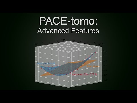
- This update includes a new optional geoRefine procedure to refine the geometrical sample model. GeoRefine uses the defocus estimated by SerialEM's CTFfind at every position's start tilt angle record image. Using these defoci it fits a plane or a paraboloid and overwrites the user given plane. Results are very much dependent on the reliability of the CTF fit and overall are probably only worth it for large collection areas (7x7 holes or more, see figure of 9x9 fit below) yielding nice FFTs. This feature was not extensively tested yet! Please use at your own discretion! Feedback and bug reports are appreciated!

- Usage: Set geoRefine to True. PACE-tomo will fit the CTF after the first Record images are taken and only use values that show a fit better than the fitLimit value. If 3 points or more remain it will fit a plane, if parabolTh (default: 9) or more values remain, it will fit a paraboloid.
- Other changes:
- Added progress bar and remaining time estimate.
- Added zeroExpTime setting to set deviating exposure time for the start tilt image.
- Added checkDewar and doCtfFind options to turn them off in case they cause problems.
- Minor text fixes.
- Small update to the target selection script, which still needs some more testing.
- Changes:
- Draws beam at tilted stage (ellipse) around targets during manual selection using the beamDiameter and the maxTilt settings. If the beamDiameter is set to 0 the script will attempt to read it from the microscope illuminated area value, which is only available on Thermo Scientific microscopes like the Krios. WARNING: To draw the beam diameter this script will add a polygon item to the navigator file and reload the navigator. Be careful and maybe make a backup of the navigator file to be safe!
- New warning when you select a target close to the SerialEM image shift limit (default: 15 microns).
- Added independent abort of a target's tilt series branches in case of image shift approaching the limit or optionally in case of dark images (minCounts setting).
- Numerical settings in the script can now be overwritten by settings in the target file. This allows for varying settings during batch acquisition of several PACE-tomo areas.
- Added option to apply additional tilt axis offsets for positive and negative branches as used for the side-entry holder dataset in the manuscript (taOffsetPos and taOffsetNeg settings). These offsets are applied on top of the global offset set in SerialEM and are only used for the internal calculations.
- Additional consideration of the rotation value should improve performance especially when estimating the geometry of a support film.
- Changed alignment buffer from M to O to allow for more Roll buffers.
- Minor text fixes.
- Added option to use SerialEM's Low Dose Search instead of View to allow for a different field of view during target selection. Search is not used for a targetPattern setup and the map for realignment of target 1 is still taken in View mode.
- Added option to run target selection on a group of points.
- Minor text fixes.