Two alphanumeric LCDs and 2 LED bars to show and manage some in-flight parameters for FS2020. In this project you can play with some Arduino programming code but you don't need any development effort on the PC side.

About the radio stack and due to the large number of planes with very different functionalities (for example, some planes have the standby frequency for the ADF and others don't), it could be necessary to customize the program to obtain some function on different aircrafts of your choice.
This project is a bit more complicated than my first pfoject (a simple Switch/LED Panel that you can find here: https://github.com/IWILZ/FS2020-Switch-Panel) but anyway i will give you every useful informations to let you build and customize your own panel.
Again i started with these main goals in my mind:
- i wanted to build it using one of my Arduino(s) i had in my drawer
- i wanted to write some code for it so i didn't chose any "high-level" developing HW/SW platform (like Mobiflight for example). They are very powerful, but i like to write my own code and solder some wires from scratch to obtain a smart solution customized on my needs
- i wanted to realize a simple, flexible and cheap panel
Like the Switch/LED Panel, you can use an Arduino board of any type (i used a Nano but the only limit is the number of I/O pins) plus some cheap other stuff like an encoder, a couple of LCDs and few LEDs and buttons (for the component list see at the end if this document).
This panel manages and shows the following parameters:
- display NAV1 & NAV2 Active frequencies
- display NAV1 & NAV2 Standby frequencies
- edit and switch NAV1 & NAV2 Standby frequencies
- display and edit radial setting of NAV1 & NAV2 (OBS)
- display and edit ADF frequency and its HDG
- when a NAVx starts to receive a valid signal, the program automatically displays its CDI on 2 LED bars (with priority to NAV1).
- on a second LCD the program displays Indicated Air Speed, Altitude (QNH), Height (QFE), HDG and Vertical Speed
I made my panel to be placed above my PC monitor so i can see all the parameters in the most comfortable way.
All the Radio frequencies and courses are shown and edited on the first 16x2 char LCD. Some plane parameter like Speed(s), Altitude, HDG, etc, are shown on a second LCD and the CDI is shown using 2 LED bars + a single 3mm green central LED. To edit each frequency and course i used an encoder + 1 button.

In the following picture you can see 3 components:
- the LCD panel (with Arduino and some buttons and LEDs)
- a program (FS2020TA.exe) that manages the bidirectional communications with FS (you will find a link to this program later in this document)
- the Flight Simulator itself.

The panel reads values and send commands to FS using the FS2020TA.exe (made by Seahawk240) as a sort of communication "repeater". The Arduino board communicates with the PC and FS2020TA.exe (that uses a SimConnect.dll) using a standard USB port. The communication protocol is very simple and will be explaned later.
What you need is:
- an ordinary Arduino board (not necessarily a Nano)
- two LCDs 16x2 chars (with serial interface)
- two led bars
- one encoder with push button
- a couple of buttons or spring switches
- some LEDs and their resistors
- a couple of small breadboards just to solder LEDs and buttons on them
- a soldering iron
- some small section wires to connect switches, LEDs, LCDs and bars to the Arduino board

For the front panel i used a piece of a carbon fiber plate but you can use also a wood plate or anything else from about 1.5 to 3mm thick.
Due to the small power consumption, the panel will be simply powered by the 5Vcc from the USB of your PC but if you add some more LEDs or devices, check the power consumption to avoid damaging your PC's USB board.
Before to start is better to spend few words about LEDs and buttons connections.
Each Arduino pin can be configured as Input or Output by the program and this is very flexible. Obviously each LED connection has to be an Output (any output pin produces a 5Vcc when at high level) and each button/switch as Input but in this last case the program have to declare it as "INPUT_PULLUP" pin to avoid random readings.
In the following picture you can see how to connect a generic LED and a generic button/switch. Each button should be "normally opened" so it will "close the circuit" to the ground only when pressed: so we could say that it's "active LOW".

To avoid a damage of the micro controller itself NEVER CONNECT A LED DIRECTLY to the Arduino, but use a resistor to limit the current flowing into it. The resistor value depends on the LED brand and colour (normally red ones needs a lower value resistor than green ones) but you could start with a value of 1KOhm and then change it to find the right value/brightness for your LED. If you have a tester you can also measure the current flowing into the LED considering that the maximum current on a output PIN of the Arduino cannot exceed 20mA. If you cannot measure the current, just look at your LED's light and don't exceed with its brightness.
In this project the encoder allow us to edit frequencies and courses just rotating its shaft so it is quite a sort of "fast button" that changes its state very quickly when is turned right or left. Furthermore, our encoder must have also a button that is activated by pressing the rotation shaft. For these reasons an encoder is a bit more complex than a simple button as you can see in the following picture but this is not a problem because the program uses the BasicEncoder library to manage it.

For this panel i've used also 2 LED bars (+ 1 green central LED) to realize a CDI (Course Deviation Indicator) when in range with a VOR station. Each bar has 10 individually driven LEDs. Eight of them are green, one is yellow and the last is red. Using these bars i can see how much deviation (left or right) is from the radial set via the OBS on a specific VOR station. The simple Grove_LED_Bar library is used to manage the bars.
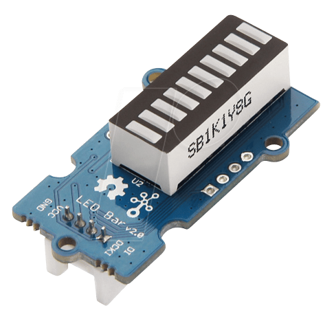
By the way, on my panel i've also added a 3mm green led just between the LED bars to show when the aircraft is centered on the VOR station radial and 2 more LEDs over the BARs to show which VOR station (NAV1 or NAV2) the CDI indication refers to.
Yes LCDs are a bit more complex, but these 2x16 chars devices are widely used in a lot of projects so they are cheap and well known. They are available in 2 versions: with and without a serial interface and in this project we need the first version because they need only 2 PINs (in addition to power supply) to be connected to an Arduino board.
The serial interface version of the LCD comes with a second small additional board that must be soldered under the bigger one. This board allows to communicate with other devices using a serial protocol on pins SDA and SCL next to GND and VCC.

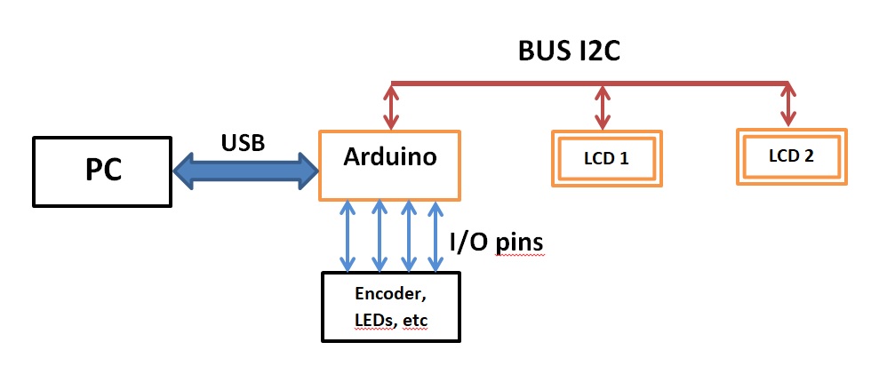
The name of the serial bus is I2C and Arduino uses it to communicate with both LCDs but obviously each of them must be uniquely identified and this is achieved by assigning them a different address soldering a tin drop between A0, A1, or A2 pads.
In my case the I2C adapters came with the predefined 0x27 address (with all pads unsoldered) and i've used the first as flight parameters LCD. Then i soldered the pad A0 on the second giving it the address 0x26 for the radio stack but when you buy your LCDs, please check how you can change the address because different brands could have different procedures and/or address ranges.
Also on the Arduino side you have to check on which pins you have to connect the I2C bus because they depends on the specific Arduino board. On the Arduino Nano for example the I2C bus must be connect on A4 and A5 pins.
I2C is a bi-directional BUS but in this project data flow only from the microcontroller to each LCD. If you are interested to get more information about I2C bus you can read here: https://en.wikipedia.org/wiki/I%C2%B2C
The following figure shows the complete bus architecture of the project. The communications from Arduino to both LCDs are done using the LiquidCrystal_I2C library.
FS2020TA.exe acts as a software "bridge" on the PC to make a bi-directional communication between the Arduino board and FS2020. The program is free, was developed by Matthias Schaaf and can be dwonloaded from: https://github.com/Seahawk240/Microsoft-FS2020-To-Arduino
The program (wich uses SimConnect.dll) is very simple and strong and the communication is made by Arduino using standard Serial functions. To get informations from FS you have to edit a sort of list within FS2020TA and then you will use Serial.readStringUntil() into the Arduino sketch. In the same way to send commands you simply have to use Serial.print().
You can also find a video description here: https://www.youtube.com/watch?v=EVqY8KhdZI8 and for more informations, please read the official documentation from Matthias Schaaf.
About FS2020 variables, you can also find some useful info here: https://docs.flightsimulator.com/html/index.htm#t=Programming_Tools%2FSimVars%2FSimulation_Variables.htm
The communications is made simply sending and receiving strings over the USB connection of the PC.
Every parameter is received as a string using "Serial.readStringUntil()" and the format is "@ID/index=value$" where '@', '/', '=' and '$' are markers to identify the 3 field "ID", "index" and "value".
- ID = idientifies each parameter
- index = idientifies different objects having the same parameter. For example when ID=502 (NAV_ACTIVE_FREQUENCY), index=1 is for the frequency of NAV1 and index=2 is the same for NAV2. When there is only 1 object to identify, index=-1 (for example for the Altitude)
- value = is the value itself and can be interpreted as an integer, float, string, degree, boolean, etc depending of the kind of parameter
Of course depending on the "ID" value, the program has to manage "value" converting it from a string to a number if necessary.
In this project all we need are the following IDs:
/*************************************************************
             Parameter IDs from FS2020
 *************************************************************/
#define ID_ADF_HDG      9       // ADF CARD (degrees HDG ADF)
#define ID_ADF_ACT_FREQ 7       // ADF ACTIVE FREQUENCY
#define ID_NAV_ACT_FREQ 502     // NAV 1 & 2 ACTIVE FREQ
#define ID_NAV_SBY_FREQ 526     // NAV 1 & 2 STANDBY FREQ
#define ID_NAV_OBS      519     // OBS 1 & 2 (degrees)
#define ID_HEADING      413     // HEADING INDICATOR
#define ID_AIRSPEED     37      // AIRSPEED INDICATED
#define ID_ALTITUDE     431     // INDICATED ALTITUDE
#define ID_QFE          557     // PLANE ALT ABOVE GROUND
#define ID_VARIOMETER   763     // VERTICAL SPEED
#define ID_NAV_CDI      505     // NAV CDI value of VORx/NAVx (range -127...+127) (index 1/2)
#define ID_NAV_HAS_NAV  516     // (Bool) NAVx active (index 1/2)
#define ID_NAV_CODES    506     // Binary mask for NAVx state (index 1/2)
FS2020TA.exe sends continuously the above list of parameters ending each one with a '\n' (for example "@37/-1=123$\n" means that we are flying at 123Knots).
Inside the main loop() of the sketch, the program calls GetParamFromFS2020() function that simply reads the next string until '\n' and stores "ID", "index" and "value" into 3 global variables. After that the program manage this parameter switching on/off a corresponding LED.
To send a command to FS you have just to send a string using Serial.print() and this is the list of all the commands we need:
/*************************************************************
                    Commands to FS2020
 *************************************************************/
#define NAV1_INC_MHZ  "@568/$"  // NAV1_RADIO_WHOLE_INC
#define NAV2_INC_MHZ  "@577/$"  // NAV2_RADIO_WHOLE_INC
#define NAV1_DEC_MHZ  "@567/$"  // NAV1_RADIO_WHOLE_DEC
#define NAV2_DEC_MHZ  "@576/$"  // NAV2_RADIO_WHOLE_DEC
#define NAV1_INC_KHZ  "@564/$"  // NAV1_RADIO_FRACT_INC_CARRY
#define NAV2_INC_KHZ  "@573/$"  // NAV2_RADIO_FRACT_INC_CARRY
#define NAV1_DEC_KHZ  "@562/$"  // NAV1_RADIO_FRACT_DEC_CARRY
#define NAV2_DEC_KHZ  "@571/$"  // NAV2_RADIO_FRACT_DEC_CARRY
#define NAV1_SWAP     "@566/$"  // NAV1_RADIO_SWAP
#define NAV2_SWAP     "@575/$"  // NAV2_RADIO_SWAP
#define OBI1_INC      "@972/$"  // VOR1_OBI_INC
#define OBI1_DEC      "@971/$"  // VOR1_OBI_DEC
#define OBI2_INC      "@975/$"  // VOR2_OBI_INC
#define OBI2_DEC      "@974/$"  // VOR2_OBI_DEC
#define ADF_100_INC   "@8/$"    // ADF_100_INC
#define ADF_100_DEC   "@7/$"    // ADF_100_DEC
#define ADF_1_INC     "@19/$"   // ADF1_WHOLE_INC
#define ADF_1_DEC     "@18/$"   // ADF1_WHOLE_DEC
#define ADF_HDG_INC   "@10/$"   // ADF_CARD_INC
#define ADF_HDG_DEC   "@9/$"    // ADF_CARD_DEC
#define ADF_FRACT_INC_CARRY   "@14/$"   // Inc, ADF 1 freq. by 0.1 KHz, with carry
#define ADF_FRACT_DEC_CARRY   "@13/$"   // Dec, ADF 1 freq. by 0.1 KHz, with carry
Due to the total number of different parameters that the program must receive (also considering that about half of those values are double) and that FS2020TA.exe cyclically sends all parameters one after the other, after some tests i realized that waiting for a specific parameter was a too slow solution.
So i chose a different strategy. At each "main loop", the GetParamFromFS2020() function stores the next parameter it receives (without expecting a specific one) into it's dedicated position inside the FromFSArray[NUM_FS_PARAM] array, ready to be used later by the program and this solution proved to be much more efficient.
For this purpose, the program uses the following array of struct so that GetParamFromFS2020() just fills the right "value" fields:
struct t_FromFS {
  int id;
  int index;
  String value;
};

#define NUM_FS_PARAM    19
t_FromFS FromFSArray[NUM_FS_PARAM] = {
  {ID_ADF_HDG,        -1, "0"},   // 0
  {ID_ADF_ACT_FREQ,    1, "0.0"}, // 1
  {ID_NAV_ACT_FREQ,    1, "0.0"}, // 2
  {ID_NAV_ACT_FREQ,    2, "0.0"}, // 3
  {ID_NAV_SBY_FREQ,    1, "0.0"}, // 4
  {ID_NAV_SBY_FREQ,    2, "0.0"}, // 5
  {ID_NAV_OBS,         1, "0"},   // 6
  {ID_NAV_OBS,         2, "0"},   // 7
  {ID_HEADING,        -1, "0"},   // 8
  {ID_AIRSPEED,       -1, "0"},   // 9
  {ID_ALTITUDE,       -1, "0"},   // 10
  {ID_QFE,            -1, "0"},   // 11
  {ID_VARIOMETER,     -1, "0"},   // 12
  {ID_NAV_CDI,         1, "0"},   // 13
  {ID_NAV_CDI,         2, "0"},   // 14
  {ID_NAV_HAS_NAV,     1, "0"},   // 15
  {ID_NAV_HAS_NAV,     2, "0"},   // 16
  {ID_NAV_CODES,       1, "0"},   // 17
  {ID_NAV_CODES,       2, "0"}    // 18
};
While flight parameters are simply continuously shown on the second LCD, to manage the radio stack on the first one the Arduino program is written like a "state machine" that sequentially switches among the following states rotating the encoder:
- NAVs display - shows NAV1 and NAV2 active frequencies and their OBS settings
- ADF display - shows ADF frequency and its HDG setting
- NAV1 editing - to change NAV1 standby frequency and OBS1
- NAV2 editing - to change NAV2 standby frequency and OBS2
- ADF editing - to change ADF frequency and its HDG
Likewise, the functions EditNav() and EditAdf() are finite-state machines that allow to edit frequency and course of each radio using the encoder and an external button that acts as an "abort-edit" command.
Of course you can extend this architecture to manage also COM1 and COM2 radio with just a little effort.
The second LCD just shows continuosly some flight parameters but 2 of them are displayed at short time intervals alternating one after the other. They are:
- vertical speed
- aircraft height over the ground (QFE)
This is because in this way the progam can optimize the 2x16 characters using only a single screen.
A couple of improvements could be the following.
At the moment the yellow button you can see above the CDI LED bars is connected to my Arduino board but not used yet and the rightmost green LED indicates when a VOR is also a localizer: the lateral component of the instrument landing system (ILS).
Even if this can be nice, probably they together could have a different use. For example they could be useful when a VOR station gives also the DME (Distance Measuring Equipment) information indicating the number of miles away from the station.
In this case when the current NAV radio provides also the DME, the LED could be switched-on and then pressing the yellow button the program could display on the "radio LCD" the VOR frequency, its radial and the distance from the station.
As mentioned above, the binary mask NAV_CODES is useful to know everything about VOR stations and these are the meanings of each bit of it (note that BIT7 indicates a localizer while BIT0 a DME):
  BIT7:[index] 0=VOR 1=Localizer
  BIT6:[index] 1=glide slope available
  BIT5:[index] 1=no localizer backcourse
  BIT4:[index] 1=DME transmitter atglide slope transmitter
  BIT3:[index] 1=no nav signal available
  BIT2:[index] 1=voice available
  BIT1:[index] 1=TACAN available
  BIT0:[index] 1=DME available
I have currently made this project and the previous Switch/LED Panel which is simpler and less CPU time consuming than this one. So could be interesting to merge them obtaining one only bigger project with the following architecture:

In this case Arduino 1 will manage not only the Switch/LED Panel but also all communications with FS via USB and will collect/store all data locally into an array of struct ready to send them to Arduino 2 when it requests a specific parameter using the I2C bus. On the other hand, on the I2C bus Arduino 2 will act as master both towards the 2 LCDs and also the Arduino 1 requesting data and sending commands for FS2020.
This new architecture also will require an autonomous power supply because the sum of the consumptions would be harmful for a single USB port.
- Arduino Nano - https://www.amazon.it/gp/product/B01FRZW24O/ref=ppx_yo_dt_b_asin_title_o06_s00?ie=UTF8&psc=1
- LCD 2x16 - https://www.amazon.it/gp/product/B07JH6GHPR/ref=ppx_yo_dt_b_asin_title_o06_s00?ie=UTF8&psc=1
- Encoder - https://www.amazon.it/gp/product/B08728PS6N/ref=ppx_yo_dt_b_asin_title_o06_s00?ie=UTF8&psc=1
- Buttons - https://www.amazon.it/gp/product/B082DBBPGC/ref=ppx_yo_dt_b_asin_title_o08_s00?ie=UTF8&psc=1
- Breadboards - https://www.amazon.it/gp/product/B073WR78M6/ref=ppx_yo_dt_b_asin_title_o08_s00?ie=UTF8&psc=1
- LEDs - https://www.amazon.it/gp/product/B06X3VT6TD/ref=ppx_yo_dt_b_asin_title_o00_s00?ie=UTF8&psc=1
- Resistors - https://www.amazon.it/ARCELI-resistore-Utilizzare-colorato-Resistenza/dp/B07PVVFMHD/ref=sr_1_6
- LED bars - https://www.reichelt.com/it/it/arduino-grove-led-bar-v2-0-grv-led-bar-v2-p191175.html
- Wires - https://www.amazon.it/gp/product/B074P726ZR/ref=ppx_yo_dt_b_asin_title_o05_s00?ie=UTF8&psc=1