3D-LiDAR and camera extrinsic calibration [paper][arxiv]
Introduction
This is an python implementation for the fully automatic and accurate extrinsic calibration of an 3D-LiDAR and the camera based on the laser's reflectance intensity.
The paper is available here.
The main features of this implementations are:
- automatic segmentation of the point cloud acquired by Velodyne 3D LiDAR
- automatic detection of the chessboard
- automatic corners detection from the chessboard's point cloud
- optimization for extrinsic calibration parameters
- various of visualization for 3D point clouds with VTK python wrapper
These features are implemented for VLP-16, HDL-32e and HDL-64e. However, they tested only with HDL-32e. We are appreciated if one could provide data of other types for testing.
Dependencies
- Python >= 2.7.9
- OpenCV
- for macOS:
brew install opencv3
echo /usr/local/opt/opencv3/lib/python2.7/site-packages >> /usr/local/lib/python2.7/site-packages/opencv3.pth
- for macOS:
- OpenGV
- for macOS:
git clone https://github.com/mfxox/opengv
cd opengv
mkdir build && cd build && cmake .. && make && make install
- for macOS:
- Point Cloud Library (PCL)
- for macOS:
brew install pcl
- for macOS:
- PCL python bindings
- for macOS:
git clone https://github.com/mfxox/python-pcl cd python-pcl python setup.py install - for macOS:
- MATLAB engine for Python:
- for macOS or Linux:
cd "matlabroot/extern/engines/python"
python setup.py install
- MATLAB python is used for corner detection from panoramic images. The OpenCV backend is also available which can be set by the backend parameter in
config.yaml, however, Opencv may fail to detect the corners. You can also use the example files (output/img_corners) of detected corners from the sample data for a try of calibration.
- for macOS or Linux:
Optional
- VTK =7.1.1: 3D Visualization
- for macOS:
brew install vtk
- for macOS:
Usage
Installation
git clone https://github.com/mfxox/ILCC
cd ILCC
python setup.py install
Explanation of files
config.py: parameter settings
img_corners_est.py: estimate corners of chessboard from images with OpenCV or MATLAB
pcd_corners_est.py: estimate corners of chessboard from the point cloud
LM_opt.py: load corresponding 2D-3D corners, calculate initial values with the PnP method, refine the result with LM method
utility.py: utility functions for various of visualization
Process data
Rosbag data need to be converted to the csv file in which points are in time order.
-
Make a folder for example named as DATA and make the image and point cloud folders DATA/img and DATA/pcd respectively.
-
Put panoramic images into DATA/img and point cloud files into DATA/pcd. The files should be named like 00XX.png or 00XX.csv.
-
Copy config.yaml to DATA and modify config.yaml according to your situation.
-
cd DATA -
Corner detection from images.
from ILCC import img_corners_est
img_corners_est.detect_img_corners()
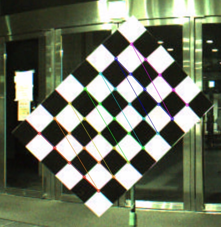
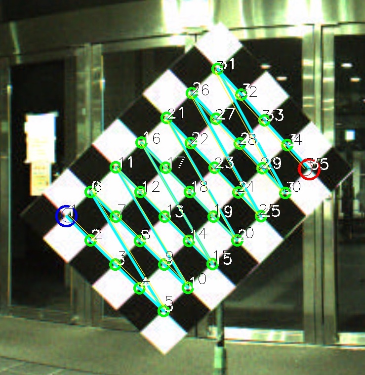
Coordinates of corners from images are saved to DATA/output/img_corners with the filename 00XX_img_corners.txt and images with marked corners are saved in the same folder with the file name 00XX_detected_corners.jpg if 'output_img_with_dectected_corners' in
config.yamlis set to True, as shown below.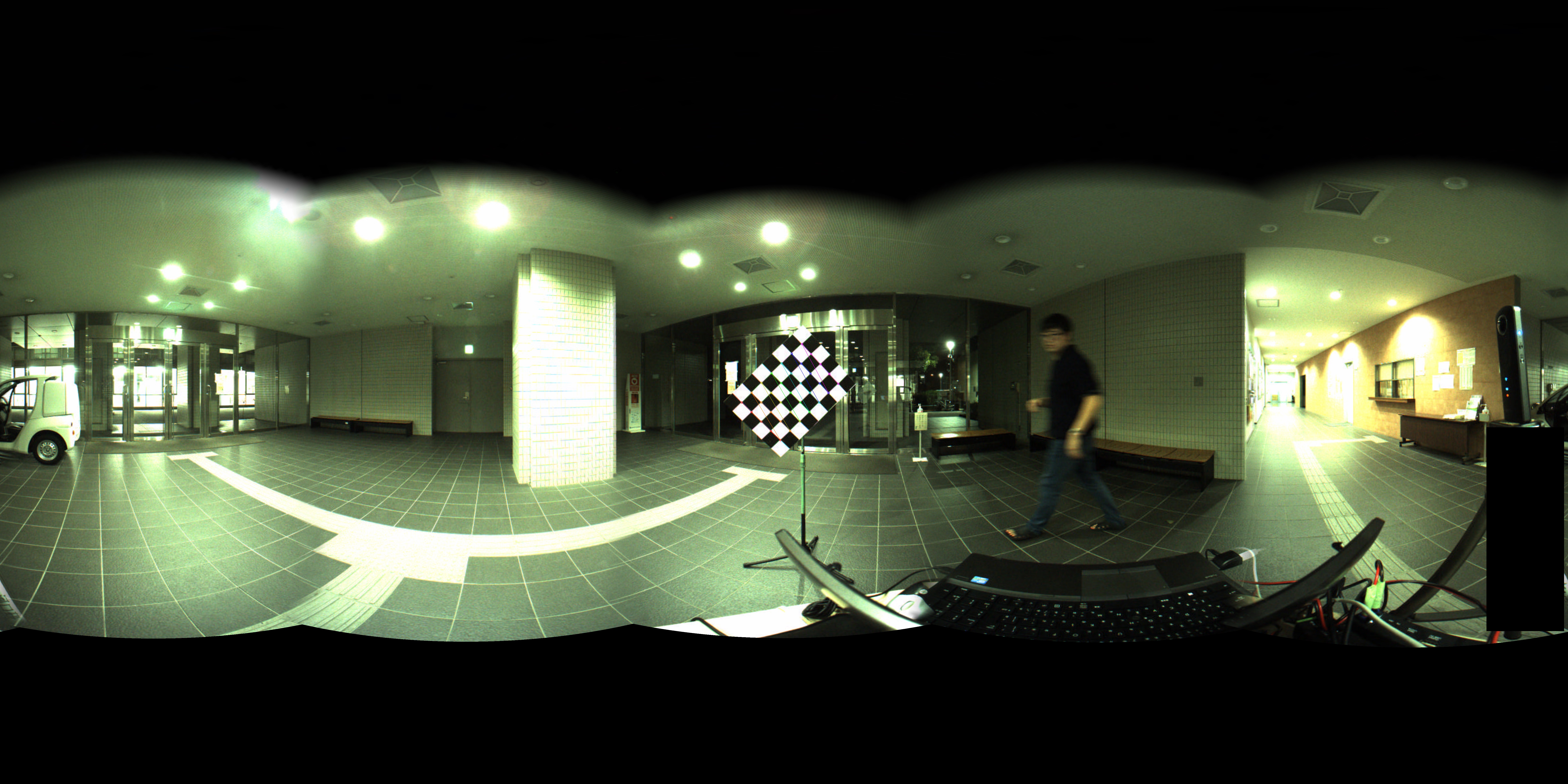
-
Corner detection from point clouds.
from ILCC import pcd_corners_est
pcd_corners_est.detect_pcd_corners()
Coordinates of corners from point clouds are save to output/pcd_seg with the filename 00XX_pcd_result.pkl. Segments of each point cloud are output to /DATA/output/pcd_seg/00XX.
-
Non-linear optimization for final extrinsic parameters.
from ILCC import LM_opt
LM_opt.cal_ext_paras()
The extrinsic calibration results are output in the end of the process and saved with the filename YYYYMMDD_HHMMSS_calir_result.txt. Images of back-projected 3D corners with the calculated parameters are saved to DATA/output if 'back_proj_corners' is set to True, as shown below.

-
After the aforementioned process, utility module can be imported for visualizing various of results.
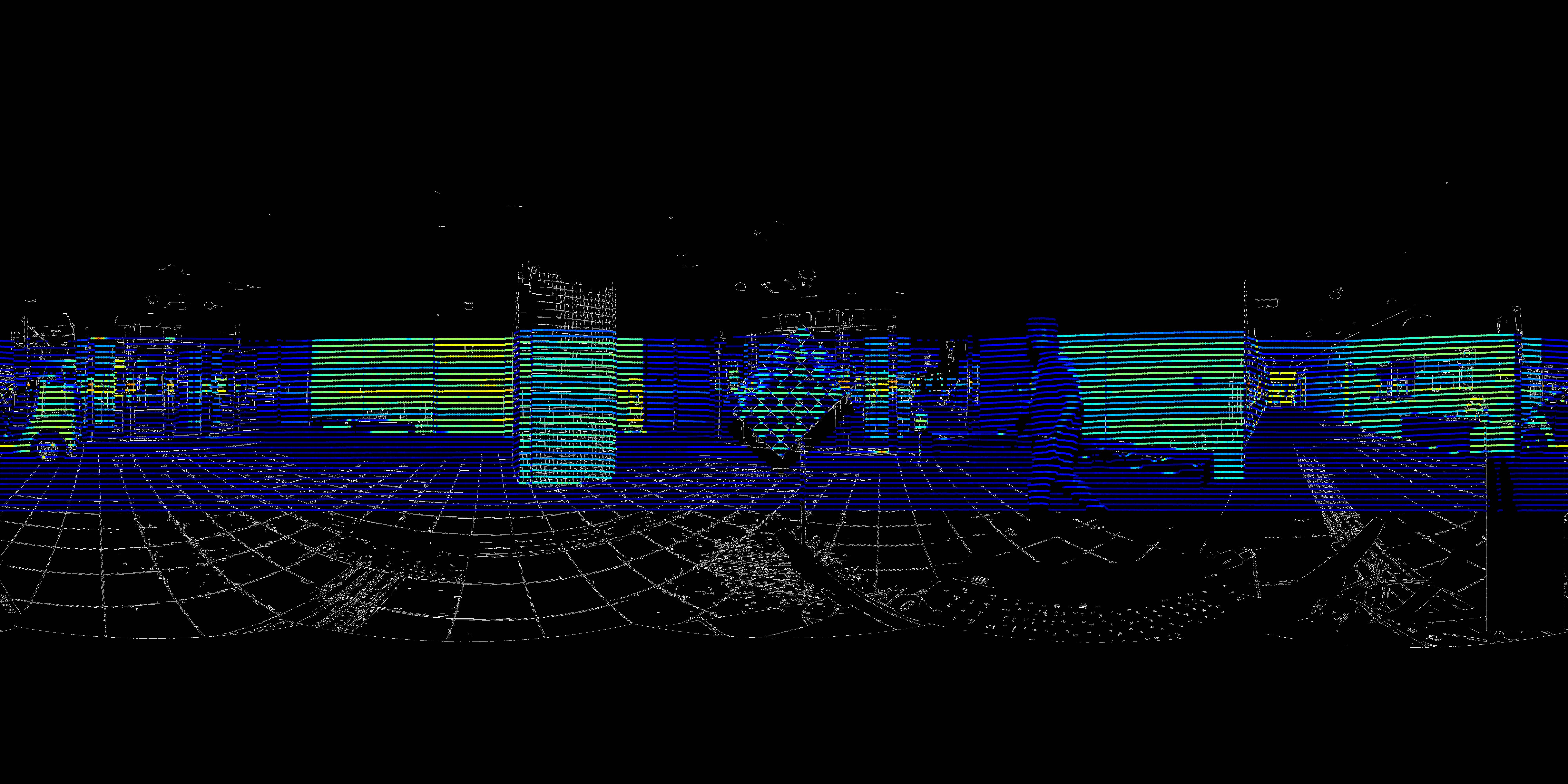
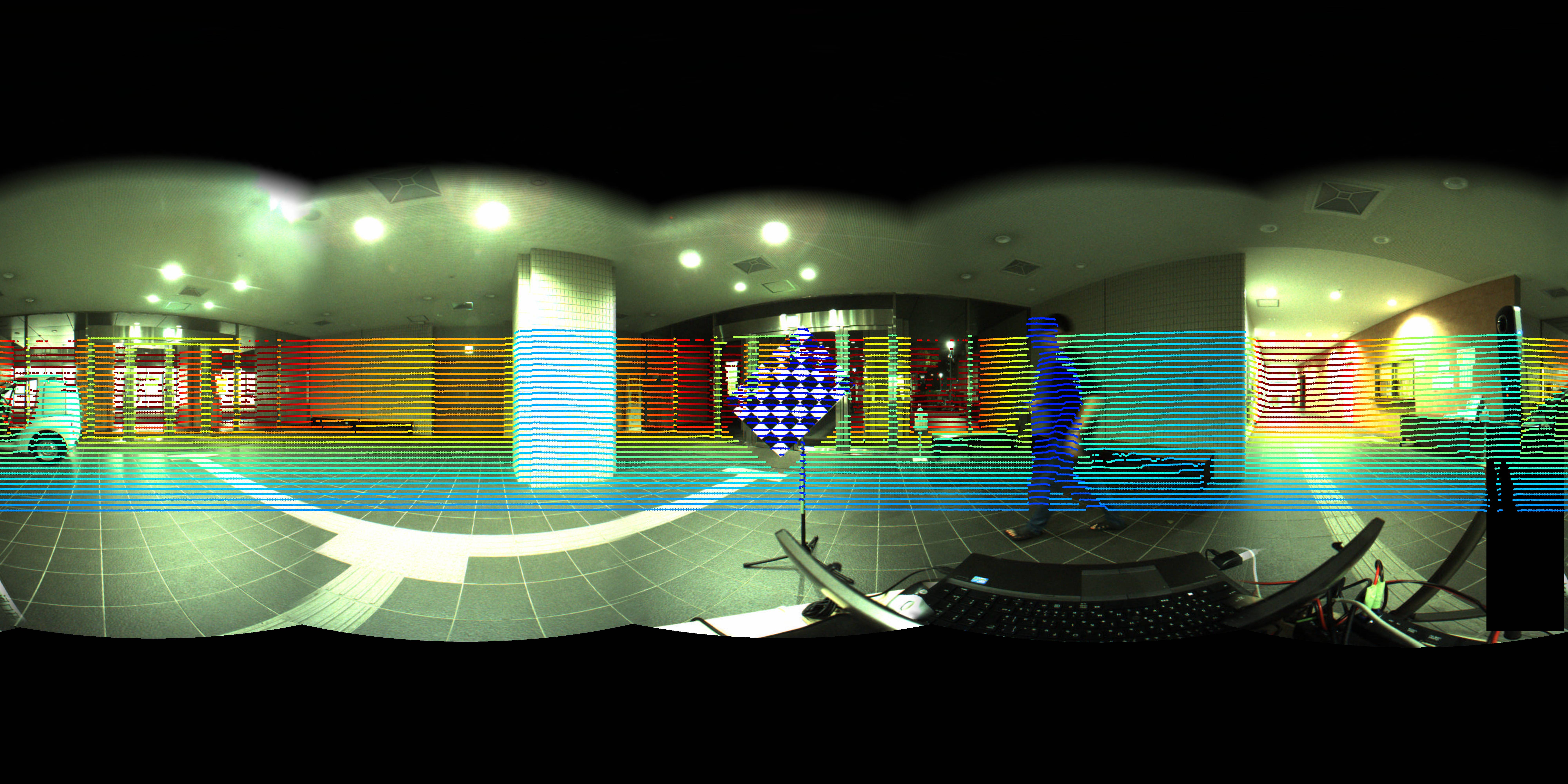
from ILCC import utility
utility.vis_back_proj(ind=1, img_style="edge", pcd_style="intens")
utility.vis_back_proj(ind=1, img_style="orig", pcd_style="dis")
The image (see below) with backprojected point cloud with the calculated extrinsic parameters will be showed and press "s" for saving. img_style can be "edge" (edge extracted) or "orig" (original image) and pcd_style can be "dis" (color by distance) or "intens" (color by intensity).
-
For 3D visualization, VTK >=7.0 is necessary. See the example below for how to use.


Example
Sample Data
The sample data and processing results of detected corners can be downloaded from here (181M).
These data are acquired with the chessboard file which contains 6*8 patterns and the length of one grid is 7.5cm if it is printed by A0 size.
Process
wget https://www.dropbox.com/s/m0ogerftqav0fyx/ILCC_sample_data_and_result.zip
unzip ILCC_sample_data_and_result.zip
cd ILCC_sample_data_and_result
copy config.yaml to ILCC_sample_data_and_result folder.
Visualization (VTK >=7.0 is necessary)
- visualization of the point cloud from .csv file
    from ILCC import utility
    utility.vis_csv_pcd(ind=1)
- visualization of the segmented results
    from ILCC import utility
    utility.vis_segments(ind=1)
- visualization of the detected point cloud segment of the chessboard
    from ILCC import utility
    utility.vis_segments_only_chessboard_color(ind=1)
- visualization of the detected point cloud segment of the chessboard and the estimated chessboard model
    from ILCC import utility
    utility.vis_ested_pcd_corners(ind=1)
- visualization of all detected chessboards
    import utility
    import numpy as np
    utility.vis_all_markers(utility.vis_all_markers(np.arange(1, 21).tolist()))

Troubleshooting
- The chessboard was not segmented properly.
- Make sure all points in the csv file are according to the time order.
- Check the LiDAR_type and laser_beams_num in
config.yamlare the same with your setup. - Try to increase jdc_thre_ratio and agglomerative_cluster_th_ratio in
config.yamlif the chessboard is over-segmented. Otherwise, decrease them if the chessboard is under-segmented.
- The chessboard seems to be segmented properly by visualizing the segmentation result with utility.vis_segments, but "no marker is found" or the wrong segment is found.
- Check pattern_size and grid_length in
config.yamlare set properly. - Check the approximate distance of the chessboard is less than marker_range_limit in
config.yaml. - Try to increase the value of chessboard_detect_planar_PCA_ratio in
config.yamlif the point cloud of the chessboard is very noisy in the normal vector direction.
For further questions, please discuss in Issues.
Tested conditions
| No. | LiDAR Model | Camera Model | Pattern Size | Grid Length[cm] | Distance Range[m] | Data source | Author |
|---|---|---|---|---|---|---|---|
| 1 | Velodyne HDL-32e |
Ladybug3 | 8*6 | 7.5 | 1.2 ~ 2.6 | link | mfxox |
Contributing
We are appreciated if you could share the collected data with different sizes or patterns of chessboard or other types of LiDAR sensors. We will acknowledge your contributions in the tested conditions' list.
If you have any question, please discuss in Issues or contact me directly.
To do list
- uniformity check with chi-square test for chessboard detection
- Integration for ROS
Add parameters for HDL-64 and VLP-16-PACK(20170614)- Add optimization for perspective camera model