In this project a DCF77 time radio receiver was connected to a DS3231 RTC module. It is controlled by an ATtiny88.
The RTC module is set to the correct time using the DCF77 receiver. If a time synchronization was successful, the DCF77 receiver is switched off for a certain time (e.g. 1 hour). The RTC time is compared with the radio time at regular intervals and the RTC is adjusted if necessary.
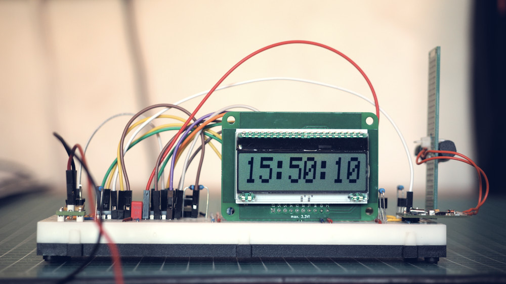
The time is displayed on an 8-digit DOGM LCD display. The display is operated with a self-made circuit board. The data for the board can be found here:https://github.com/DoImant/DOGM-LCD-Carrier-Board
There are two buttons to control the display. One controls the date display, the second the backlight.
When pressing the date display button, the current date is displayed for 10 seconds. The display then automatically switches back to the time display. The second button turns on the backlight. If it is only pressed briefly (< 1 second), the backlight is only switched on for a certain period of time (10 seconds). It then turns itself off again. If the button was pressed for a longer time (>= 1 second), the backlight remains active until the button is pressed again.
The power consumption is (at 3V operating voltage) around 2,3mA when DCF and RTC clock are running simultaneously. It drops to about 1.5mA when only the RTC and the display are active. The backlight needs about 4-5mA additionally at the programmed brightness. The desired brightness can be adjusted in the program code. The clock can therefore be operated well battery-backed with a small solar cell.
If the RTC is currently being synchronized with the radio clock, this is indicated by a dot between minutes and seconds in the display. If both clocks are in sync, a colon is displayed.
The software should also works with the pin-compatible AVR controllers ATmega8, ATmega88 and ATmega328 (e.g. Arduino nano, uno, pro mini).
The used DCF77 receiving module DCF-2 is distributed by ELV https://de.elv.com/dcf-empfangsmodul-dcf-2-091610?fs=690476457. If another module is used, the circuit may need to be adjusted. In the program code (dcf77conf.h) there is a definition "#define ACTIVE_LOW " that must be commented out if the receiving module outputs the time signals active high.
The clock will be set. This is indicated by a dot on the display

The clock is set. The dot becomes a colon
Rear view

