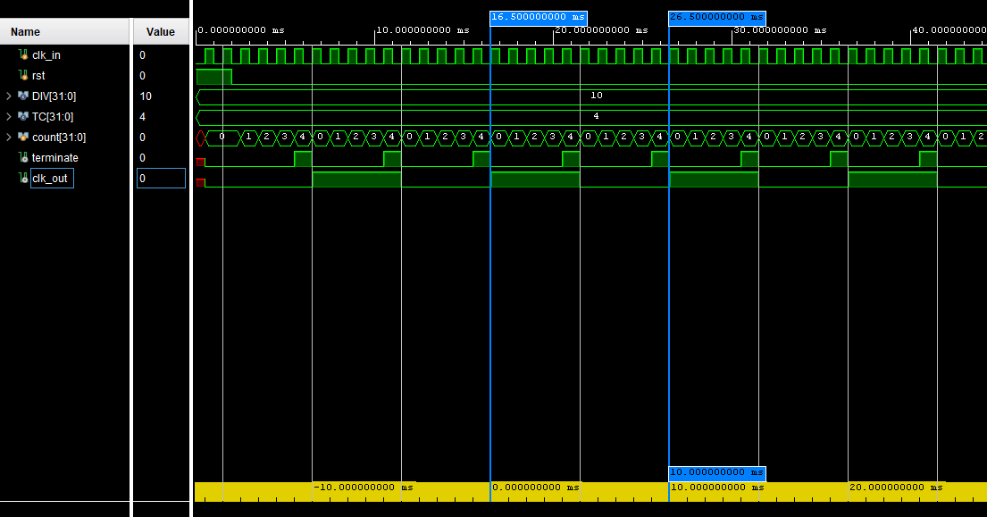
In the testbench, a 1 kHz (1 ms period) clock is generated for clk_in. The DIV parameter for the clk_divider module is set to 10, to divide the frequency of clk_in by 10 and produce a clk_out of 100 Hz. In clk_divider, a DIV of 10 means that TC (terminal count) is 4. So when count is 4, terminate is activated, and clk_out has a rising or falling edge. The simulation waveform shows that clk_out has a period of 10 ms, so a frequency of 100 Hz. It has a rising edge once every 10 cycles on clk_in.
