This is a tutorial project created by a big cat (me) in order to learn ray tracing.
This library is in RenderLib, with function to create a binary .ppm(P6) format. Following is an example of library generated by RenderLib. This is a circle in the square, with 256x256 pixel. This lib will be the basis of following ray tracing code.
First we need to build a background imag, the background is gradually changing from blue to white, which looks like follows (the image is 400 pixels height x 800 pixels width).

Now that we have the background image, we can draw a sphere on the basis of it. The equation to describe a sphere looks like follows.
where $ \mathbf{r_c} = (x_c, y_c, z_c) $ being the coordinate of sphere cneter, and
where
We can simply judge if the ray has hit the surface by the following variable:
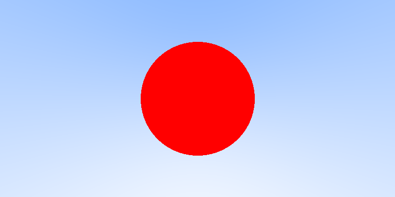
We have hit, tangent to and away from sphere 3 situations, correponding to $ \Delta >0, \Delta =0, \Delta <0$ three cases. After knowing the hit situation of each ray, it is easy to draw a sphere as follows.
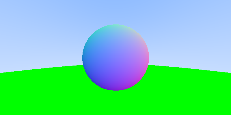
From the above chapter, we can have the intersection point between the sphere and the ray, therefore it is easy to computer the normal vector of hit point. By calculating the normal vector and give colors to pixels according to the normal vector of the sphere surface, we can render the surface as follows.
Of course, we need a library that can handle multiple objects, so we design an abstract parent class geometry, which has two method, intercept and color, the first one return the parameter t where the ray intercepts with the geometry object, the second decide the surface color of object which hit a ray. This can be seen as follows. Here we place another green sphere as the background. So we can see a "green background".
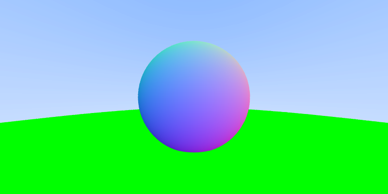
We can see some aliasing in the above spheres, in oder eliminate this aliasing effects, we need to sample several rays for one pixel. This can be done by randomly add some real numbers between 0 and 1, and average the output of the rays. The more random number we sampled, the better anti-aliasing effect is. Owing to the large number sampling will slow down the rendering speed, here we only use a sampling number equals to 10. Following is the effect. We can observ improvement of rendering qualiies (especially the boundary of spheres).
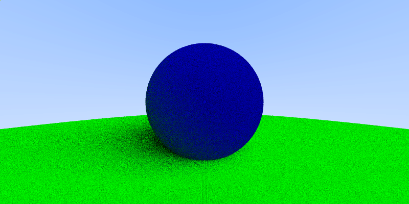
Starting from this chapter, we are going to consider the material of sphere. The material of sphere will decide the appearance of a whole material. A simple class of material is called diffuse material. That means, if a light is shade on to the material, it will randomly bounces into any directions. Here we will use a uniform distribution to simulate this behavior. By simulating the ray bouncing many times, we can get the image as follows. We can find the ball is something like plastic, and we can find some shadow near the sphere.
Then we can start with metal material. Then metal material is different from the diffuse material that it can reflect the light with some specified directions. We would like to specify a reflectivity and diffusity for this material. In the following graph, we can find two metal spheres reflecting to each other.
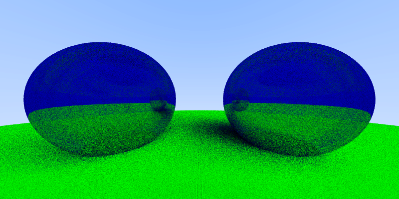
We can also add some diffusive effects on the metals, in the following graphs, the sphere in the left the the one with diffusity equals to 0.5, and the right one is the one with diffusity equals to 0.0 (mirror reflection). Notice here we have add an anti-aliasing x100, and it seems to be clearer than the usually x10 we use.
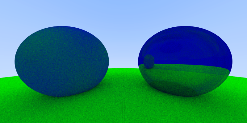
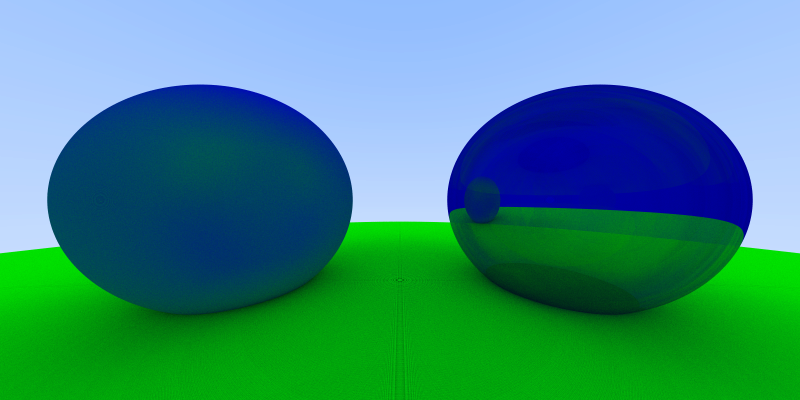
Of course, we can have images with more sampling, see the image below. Now it looks super clear (x1000)! And we can also change the color to make the sphere looks like a mirror.
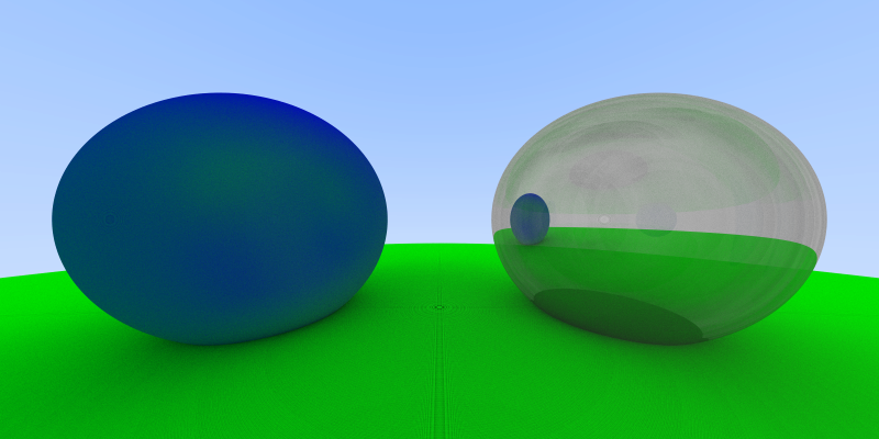
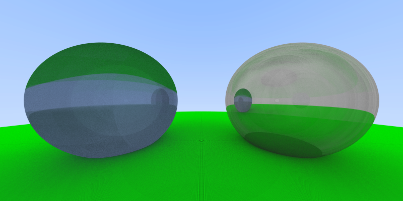
Many materials has both reflection and refraction part. The reflection part can be described as follows, and the refraction part can be described with Snell's law, where n is the refraction indices (for air the value is near 1.0, and for glass the value is near 1.3-1.7)

