- About this Project
- Working Games
- Checkout Repository
- Nexys Video Build
- Arty Z7-20 Build
- CMOD A7 Build
- Simulation Build
- Unit-Tests
- Native Build
- Windows Build
- RP2040 Build
- Zynq Build
- Port to a new platform
- Missing Features
- Next Possible Steps
The Rasterix project is a rasterizer implementation for FPGAs written in Verilog. It implements a mostly OpenGL 1.3 compatible fixed function pixel pipeline with a maximum of two TMUs and register combiners in hardware. The vertex pipeline is implemented in software. The renderer is currently able to produce 100MPixel and 200MTexel at a clockspeed of 100MHz.
The long term goal of this project is to recreate an open source fixed function renderer compatible with all fixed function APIs (OpenGL 1.5, OpenGL ES 1.1, Glide, Direct 3D 7.0) and is also suitable for embedded devices. The current focus is on OpenGL.
It comes in two variants, RasterixIF and RasterixEF. IF stands for internal framebuffer while EF stands for external framebuffer. Both variants have their advantages and drawbacks. But except of the framebuffer handling and resulting limitations (because of AXI strobe limitations: stencil is applied on the whole value, not per bit, color mask does also not work per color, only on the whole fragment, no alpha channel), they are completely equal.
RasterixIF: This variant is usually faster, because it only loosely depends on the memory subsystem of your FPGA since the rendering is completely executed in static RAM resources of your FPGA. But the drawback is (you might already guess) the occupation of a lot of RAM resources of your FPGA.
For a reasonable performance, you need at least 128kB + 128kB + 32kB = 288kB memory only for the framebuffers. Less is possible but only useful for smaller displays. More memory is generally recommended.
The used memory is decoupled from the actual framebuffer size. If a framebuffer with a specific resolution won't fit into the internal framebuffer, then the framebuffer is rendered in several cycles where the internal framebuffer only contains a part of the whole framebuffer.
RasterixEF: The performance of this variant heavily depends on the performance of your memory subsystem since all framebuffers are on your system memory (typically DRAM). While the latency is not really important for the performance but the the number of memory request the system can execute, is even more. This is especially in the Xilinx MIG a big bottleneck for this design (because of this, it is around two times slower that the RasterixIF). Contrary to the RasterixIF, it don't uses FPGA memory resources for the framebuffers. They are free for other designs, but it needs a bit more additional logic to handle the memory requests.
With the following settings:
- 32 bit command bus / memory bus
- 128px textures
- 1 TMU
- no mip mapping
- float precision of 24 bit
- internal framebuffer (rrxif)
Then the core requires around 14k LUTs on a Xilinx Series 7 device. More is possible by reducing the float precision even more, but then the interpolation errors will come more and more visible.
A high configuration
- 128 bit command / memory bus
- 256px textures
- 2 TMUs
- mip mapping
- float precision of 32 bit
- external frame buffer (rrxef)
Then the core requires around 36k LUTs on a Xilinx Series 7 device.
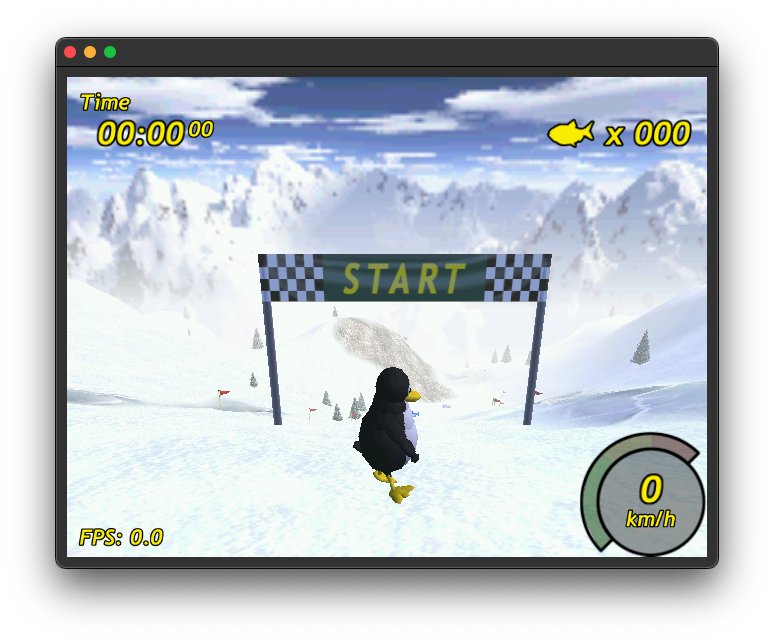
Tested games are tuxracer (please see https://github.com/ToNi3141/tuxracer.git and the Branch RasterixPort), Quake 3 Arena with SDL2 and glX (https://github.com/ToNi3141/Quake3e) and others.
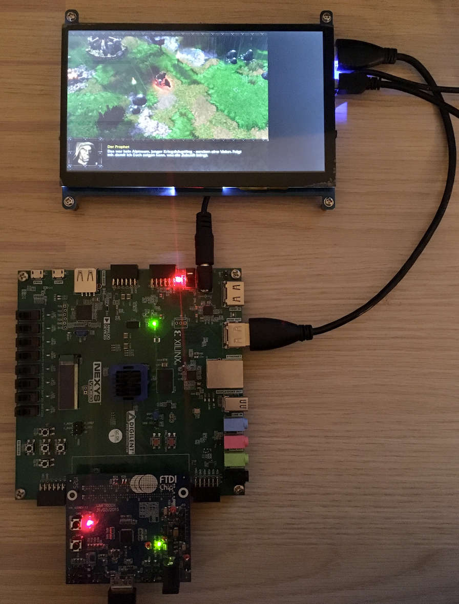
Warcraft 3 (with WGL) under windows is also working.
Use the following commands to checkout the repository:
git clone https://github.com/ToNi3141/Rasterix.git
cd Rasterix
git submodule init
git submodule updateThe build target is a Nexys Video board with an XC7A200 FPGA. The interface used to connect the FPGA with the PC is an 16bit synchronous FT245 protocol on the Nexys FMC connector.
There are two variants available:
rrxif:
- 2 TMU (max res: 256x256)
- Mip mapping
- Framebuffer size: 256kB + 256kB + 64 kB
rrxef:
- 2 TMU (max res: 256x256)
- Mip mapping
You can build it in two variants, rrxif and rrxef. Depending on the variant, you must enable the VARIANT_RRXIF or VARIANT_RRXEF for the library build.
To build the binaries use the following commands.
cd rtl/top/Xilinx/NexysVideo
/Xilinx/Vivado/2022.2/bin/vivado -mode batch -source build_rrxif.tcl
You will find rasterix.bin and rasterix.bit in the synth directory. Use Vivado to program the FPGA or to flash the binary into the flash.
Connect the Nexys Video via USB 3.0 to your computer (via the UMFT600X-B eval board). Connect to your Nexys Video a 1024x600 px monitor. If you don't have a monitor at hand with this resolution, you have to change the resolution in the rtl/Display/Dvi.v wrapper and in the software (for instance in example/minimal/main.cpp).
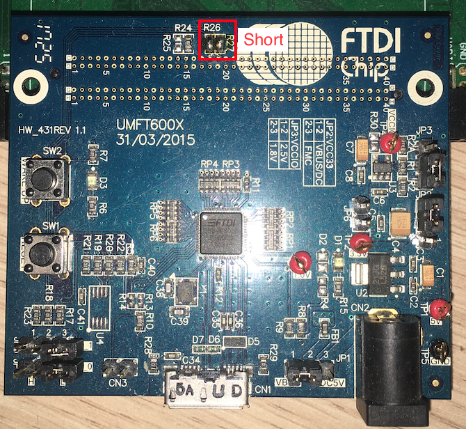
The current implementation uses a UMFT600X-B eval board from FTDI with an FT600 to connect the Nexys with an PC. It offers a USB 3.0 connection and can be connected via the FMC connector.
The UMFT600X-B must be prepared:
- JP1: 1-2 (VBUS)
- JP2: 2-3 (Select powered by FIFO master Board(default))
- JP3: 1-2 (VCCIO=2.5V(default))
- JP4: Open (Multi-Channel FIFO)
- JP5: Open (Multi-Channel FIFO)
- JP6: Open
Also the following solder bridges must be applied:
- R26: Short (GPIO: Triggers the reset line)
- R27: Short (GPIO)
The build target is an Arty Z7-20 board with an XC7Z020 SoC. It expects petalinux running on the board. It will by default output a 1024x600px video signal on the HDMI OUT. Just connect there a monitor which can handle this resolution.
There are two variants available:
rrxif:
- 1 TMU (max res: 256x256)
- Mip mapping
- Framebuffer size: 128kB + 128kB + 32 kB
rrxef:
- 2 TMU (max res: 256x256)
- Mip mapping
To build the binaries use the following commands.
cd rtl/top/Xilinx/ArtyZ7-20
/Xilinx/Vivado/2022.2/bin/vivado -mode batch -source build_rrxef.tcl
You will find rasterix.bin and rasterix.bit in the synth directory. You will also find there the design_1_wrapper.xsa file which is used for petalinux.
The build target is a CMOD A7 board with an XC7A35 FPGA. The interface used to connect the FPGA with a host is an SPI interface with additional CTS pin for flow control (in software).
This builds the RasterixIF and uses one TMU with a maximum texture resolution of 128x128px. The framebuffers have a size of 64kB + 64kB + 16kB.
There is one variant available:
rrxif:
- 1 TMU (max res: 128x128)
- No mip mapping
- Framebuffer size: 64kB + 64kB + 16kB
To build the binaries, use the following commands.
cd rtl/top/Xilinx/CmodA7
/Xilinx/Vivado/2022.2/bin/vivado -mode batch -source build.tcl
You will find rasterix.bin and rasterix.bit in the synth directory. Use Vivado to program the FPGA or to flash the binary into the flash.
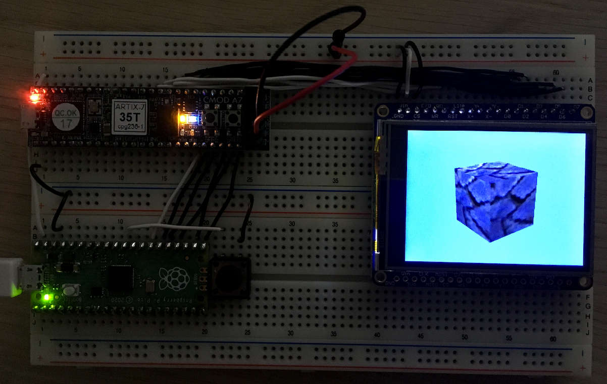
The following hardware setup shows an Raspberry Pi Pico connected to an CMOD A7 with an XC7A35 FPGA connected and an 320x240 pixel display with an ILI9341 chipset.
The Pico is connected via SPI to the CMOD. Have a look at the following table to connect them:
| Port Name | Pico | CMOD A7 |
|---|---|---|
| MISO | GP16 | 48 |
| CSN | GP17 | 46 |
| SCK | GP18 | 47 |
| MOSI | GP19 | 45 |
| CTS | GP20 | 44 |
| RSTN | GP21 | 43 |
Supported SPI clock speed: Around 50MHz.
The display is directly connected to the FPGA via the 8080-I parallel interface. The FPGA automatically configures the display when reset is asserted. To connect the display use the following table:
| Port Name | CMOD A7 | ILI9341 |
|---|---|---|
| CS | n/c | GND |
| C/D | 12 | C/D |
| WR | 10 | WR |
| RD | 09 | RD |
| RST | n/c | 3.3V |
| DATA[7:0] | [1:8] | D[7:0] |
A simulation can be used to easily develop and debug the renderer. The simulation can be found under example/qtDebug/qtRasterizerFpga. There is a Qt project which can be opened with the QtCreator. This project supports also the real hardware, which can be selected with the TARGET_BUILD variable in the .pro file.
Before building the simulation, create the C++ code from the Verilog source via Verilator 4.036 2020-06-06 rev v4.034-208-g04c0fc8aa. Use the following commands:
cd rtl/top/Verilator
make -f Makefile.linux rrxif -j
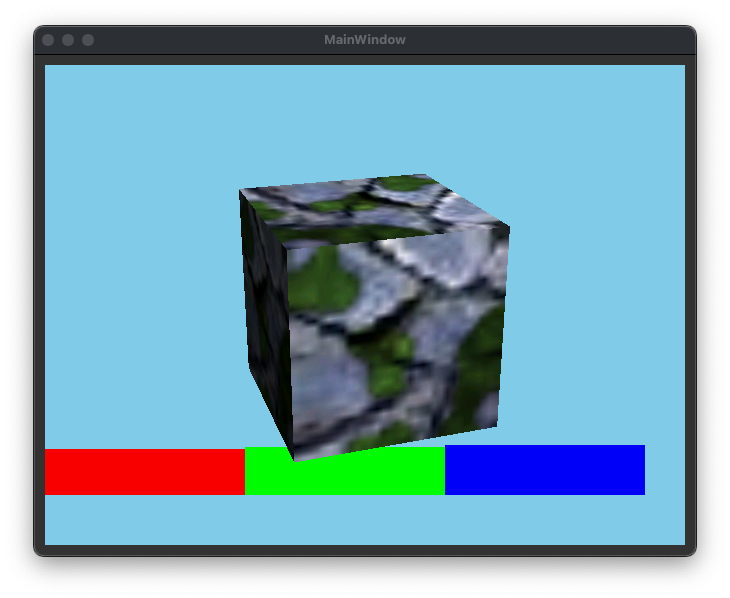
Then build the Qt project. If the build was successful, you will see the following image on the screen, when you have started the application:
You see here a cube with enabled multi texturing and lighting. Below you can see RGB colors testing the scissor.
It is likely, that your verialtor installation has another path than it is configured in the qtRasterizer.pro file. Let the variable VERILATOR_PATH point to your verilator installation and rebuild the project.
Note: Currently the build is only tested on OS X and linux. The .pro file must be adapted for other operating systems.
There exists a second project example/qtDebug/qtRasterizerGL. This project uses the native OpenGL implementation of your machine. You can compare this output with the output of the simulation. The content must be equal.
Unit-tests for the Verilog code can be found under ./unittests.
Just type make in the unit-tests directory. It will run all available tests.
Uses the Nexys Video Build.
Before configuring and starting the build, download from FTDI (https://ftdichip.com/drivers/d3xx-drivers/) the 64bit X64 D3XX driver version 0.5.21. Unzip the archive and copy the osx directory to lib/driver/ft60x/ftd3xx/.
Before starting the build, download from FTDI (https://ftdichip.com/drivers/d3xx-drivers/) the 32bit X86 D3XX driver version 1.3.0.4. Unzip the archive and copy the win directory to lib/driver/ft60x/ftd3xx/.
Before configuring and starting the build, download from FTDI (https://ftdichip.com/drivers/d3xx-drivers/) the 64bit X64 D3XX driver version 1.0.14. Unzip the archive and copy the osx directory to lib/driver/ft60x/ftd3xx/.
To build the library an the minimal example, switch to the source directory and type
cd <rasterix_directory>
cmake --preset native -DVARIANT_RRXIF=ON
cmake --build build/native --config Release --parallel
Note for Windows: you might better use the win32 preset, it is specifically for windows (see Windows Build). Otherwise configure it with cmake --preset native -G "Visual Studio 16 2019" -A Win32 -DVARIANT_RRXIF=ON otherwise the build might fail.
To run the minimal example, type
cd build/native
./example/minimal/minimal
into your terminal. It should now show an image similar to the simulation.
Uses the Nexys Video Build.
This is a more specific preset for windows which also builds WGL. Please refer to the Windows section as a precondition for this build.
Open a terminal. Use the following commands to create a 32bit Visual Studio Project:
cd <rasterix_directory>
cmake --preset win32 -DVARIANT_RRXIF=ON
cmake --build .\build\win32\ --config Release --parallel
You will find the OpenGL32.dll in the build directory. The DLL is build for 32bit targets because games from that era are usually 32bit builds. To test the build, type
cd build\win32
.\example\minimal\Release\minimal.exe
into your terminal. It should now show an image similar to the simulation.
Note: You need the FTD3xx.dll in you execution directory. It is automatically copied to the build directory.
Only classic Warcraft 3 will work. Reforged does not.
- Prepare Warcraft 3. Set the resolution to something like 800x600 or below and set the texture quality to low (currently the Renderer supports only textures with a maximum size of 256x256).
- Copy the
OpenGL32.dlltogether with the 32bit version of theFTD3XX.dllin the root directory of your Warcraft 3 installation. - Add a shortcut to the
Frozen Throne.exeorWarcraft III.exeon your desktop. Edit the shortcut and write-openglafter the path of the exe ("C:\path\to\warcraft3\Frozen Throne.exe" -opengl) to start Warcraft 3 in OpenGL mode. - Open Warcraft 3 via the shortcut. You should now see the menu on the screen connected to the FPGA.
Warcraft 3 runs on low settings with around 20-30FPS.
Switching the resolution and videos are currently not working.
Uses the CMOD A7 Build.
Before you start to build, have a look at the rp2040 SDK readme (https://github.com/raspberrypi/pico-sdk). You have several options, which are supported. The option documented there is based on a already cloned SDK on your computer.
Open a terminal. Use the following commands to build a rp2040 binary:
cd <rasterix_directory>
cmake --preset rp2040 -DPICO_SDK_PATH=<path_to_the_sdk>
cmake --build build/rp2040 --config Release --parallel
You will find a minimal.uf2 file in the build/rp2040/example/rp-pico directory.
Uses the Arty Z7-20 Build.
The Zynq build expects a petalinux SDK. Before starting to build, create a petalinux distribution and use the SDK for this build.
Use the following layout:
> fdisk -l /dev/sdc
Disk /dev/sdc: 29.72 GiB, 31914983424 bytes, 62333952 sectors
Disk model: USB  SD Reader
Units: sectors of 1 * 512 = 512 bytes
Sector size (logical/physical): 512 bytes / 512 bytes
I/O size (minimum/optimal): 512 bytes / 512 bytes
Disklabel type: dos
Disk identifier: 0xafa8e6ad

Device     Boot   Start      End  Sectors  Size Id Type
/dev/sdc1          8192  1056767  1048576  512M  b W95 FAT32
/dev/sdc2       1056768 62332927 61276160 29.2G 83 Linux
Use for sdc1 the following label: BOOT
Use for sdc2 the following label: rootfs
The following steps will give you a hint how to build and install petalinux. As precondition you must have build the hardware and have installed the petalinux tools.
# Set environment variables (if not already done)
source /opt/pkg/petalinux/settings.sh

# Create project
petalinux-create --type project --template zynq --name artyZ7_os_rrx
cd artyZ7_os_rrx

# Configure petalinux
petalinux-config --get-hw-description '/home/<username>/Rasterix/rtl/top/Xilinx/ArtyZ7-20/synth'
# Now set the following configuration:
#   Image Packaging Configuration --> Root filesystem type (EXT4 (SD/eMMC/SATA/USB))

# Copy the pre configured device tree overlay
cp /home/<username>/Rasterix/lib/driver/dmaproxy/kernel/system-user.dtsi project-spec/meta-user/recipes-bsp/device-tree/files/system-user.dtsi

# Build
petalinux-build
petalinux-package --boot --fsbl ./images/linux/zynq_fsbl.elf --fpga ./images/linux/system.bit --u-boot --force

# Copy the files to your SD card
cp ./images/linux/BOOT.BIN ./images/linux/boot.scr ./images/linux/image.ub /media/BOOT
sudo tar -xzf ./images/linux/rootfs.tar.gz -C /media/rootfs
Now you can plug the SD card into your ArtyZ7. It should now boot. If not, please refer the official documentation.
The Zynq build requires a kernel driver to transfer data via DMA to the renderer. You can find the sources for the kernel driver in lib/driver/dmaproxy/kernel. Use petalinux to create a kernel driver and use the sources in this directory to build the kernel driver. This driver is a modification of Xilinx's dma-proxy driver. This directory also contains the device tree overlay which contains memory allocations for the graphics memory and entries for the dma proxy.
# Create a symbolic link of the dmaproxy driver into the petalinux modules
ln -s '/home/<username>/Rasterix/lib/driver/dmaproxy/kernel/dma-proxy' '/home/<username>/ZynqRasterix/artyZ7_os_rrx/project-spec/meta-user/recipes-modules/'

# Build the kernel module
petalinux-build -c dma-proxy

# Copy it to your target
scp ./build/tmp/sysroots-components/zynq_generic/dma-proxy/lib/modules/5.15.36-xilinx-v2022.2/extra/dma-proxy.ko petalinux@192.168.2.120:/home/petalinux/
Load the driver on the target with sudo insmod dma-proxy.ko.
The SDK is used to build examples.
# Build the petalinux SDK
petalinux-build --sdk

# Install the SDK (for instance to /opt/petalinux/2022.2/)
sh images/linux/sdk.shOpen a terminal. Use the following commands:
cd <rasterix_directory>
export SYSROOTS=/opt/petalinux/2022.2/sysroots
cmake --preset zynq_embedded_linux -DCMAKE_TOOLCHAIN_FILE=toolchains/toolchain_zynq.cmake -DVARIANT_RRXEF=ON
cmake --build build/zynq --config Release --parallel
Now you can copy the binaries in build/zynq/example to your target (for instance via scp) and execute them. You should now see on your screen the renderings.
It also builds the libGL.so library, which implements a very basic glX API and exposes the OpenGL API. The current implementation of the glX API should be sufficient to play games like Quake3e without modifications, or to use it with SDL.
To reload the FPGA content, copy the bin file (scp synth/rasterix.bin petalinux@192.168.2.120:/home/petalinux/) in the synth directory onto your target. Then use the following commands on the target to load the new bit stream.
sudo rmmod dma-proxy.ko
sudo fpgautil -b rasterix.bin -f Full
sudo insmod dma-proxy.koPlease have a look at lib/driver. There are already a few implementations to get inspired.
To port the driver to a new interface (like SPI, async FT245, or others) use the following steps:
- Create a new class which is derived from the
IBusConnector. Implement the virtual methods. - Instantiate and use this class for the
Renderer. If you use a microcontroller, you might lackstd::future, then you can useRendererMemoryOptimized. - Add the whole
lib/gl,lib/3rdPartyandlib/driverdirectory to your build system. - Build
Please use rtl/top/Verilator/topMemory.v as an simple example. Or have a look at the build script and the block diagram from the Nexys Video in rtl/top/Xilinx/NexysVideo to have a real world example.
- Add the following directories to your project:
rtl/Rasterix,rtl/Util, andrtl/Float. - Instantiate the
Rasterixmodule. When configuring the module, make sure that the following parameters are equal to the template parameter fromRenderer.hpp:- Write a RenderConfig specifically for your design. See
RenderConfigs.hppfor examples and documentation.
- Write a RenderConfig specifically for your design. See
- Connect the
s_cmd_axisinterface to your command stream (this is the output from theIBusConnector). - Connect the
m_mem_axiinterface to a memory. Make sure to adapt the template parameter from theRenderer.hppRenderer::MAX_NUMBER_OF_TEXTURE_PAGESto the size of the connected memory. One page has 4 kB. If you have a connected memory with 512kB, you should setRenderer::MAX_NUMBER_OF_TEXTURE_PAGESto 128. - Connect
m_framebuffer_axisto an device, which can handle the color buffer stream (a framebuffer or a display for instance). - Connect
resetnto your reset line andaclkto your clock domain. - Synthesize.
The following features are currently missing compared to a real OpenGL implementation
- Logic Ops
- ...
- Add the possibility to use more than one render context
- Implement Logic Ops
- Implement a texture cache to reduce the memory consuption by omitting the
TextureBuffer - Implement higher texture resolutions
- ...
