Implementation of paper - Sample Pose Augmentation and Adaptive Weight-Based Refinement for 3D LiDAR-Camera Extrinsic Calibration Using an Orthogonal Trihedron
This is an example for testing an offline 3D LiDAR-camera extrinsic calibration, based on an orthogonal trihedral target with a checkered pattern on each plane.
It is implemented using OpenCV 4.6.0. Please refer to OpenCV installation and settings here.
The synthetic data was generated using Blensor. The Blensor is a free open-source simulation package for LIDAR/LADAR and Kinect sensors.
The simulation is available here.
In general, the order and direction of the LiDAR coordinate system are different from the camera coordinate system. The test data and program assume that the LiDAR and camera coordinate systems are on the same axis order and direction. If you use this program with other data, you must consider this. For example, change the coordinate axes and direction of the point cloud to be the same as the camera coordinate system and then run it.
There are four examples in tester.h:
testBlensor(), findCameraIntrinsicInReal(), calibrateInReal(), calibrateInReal2().
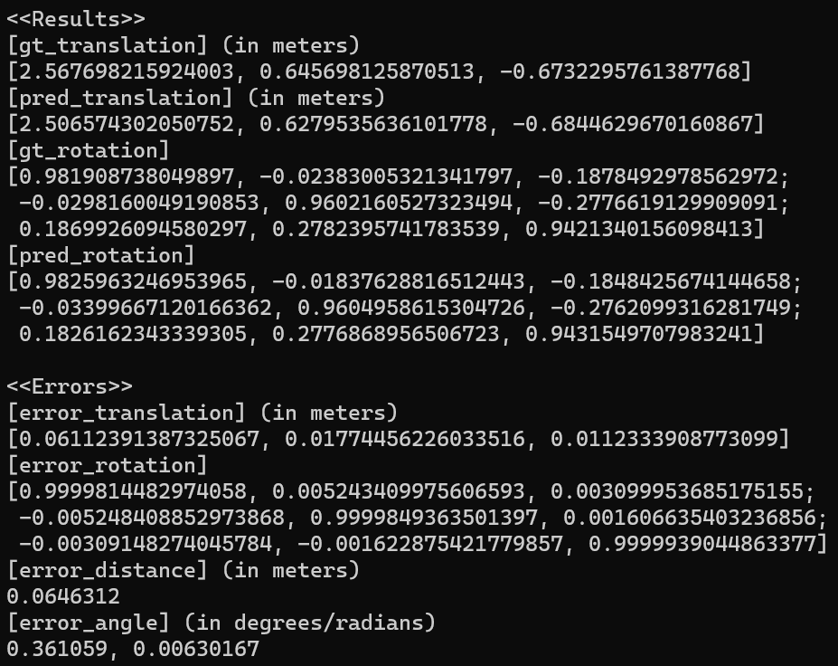
In testBlensor(), the accuracy of the estimated pose is evaluated by comparing it to the ground-truth pose.
The test results for "pointcloud_noisy_positional_0.07.pcd" are below.
- Pose estimation and error results
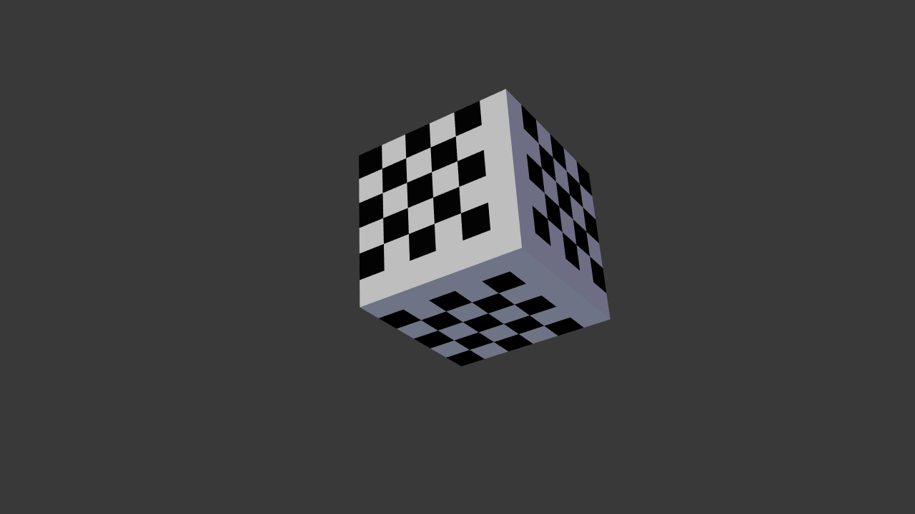
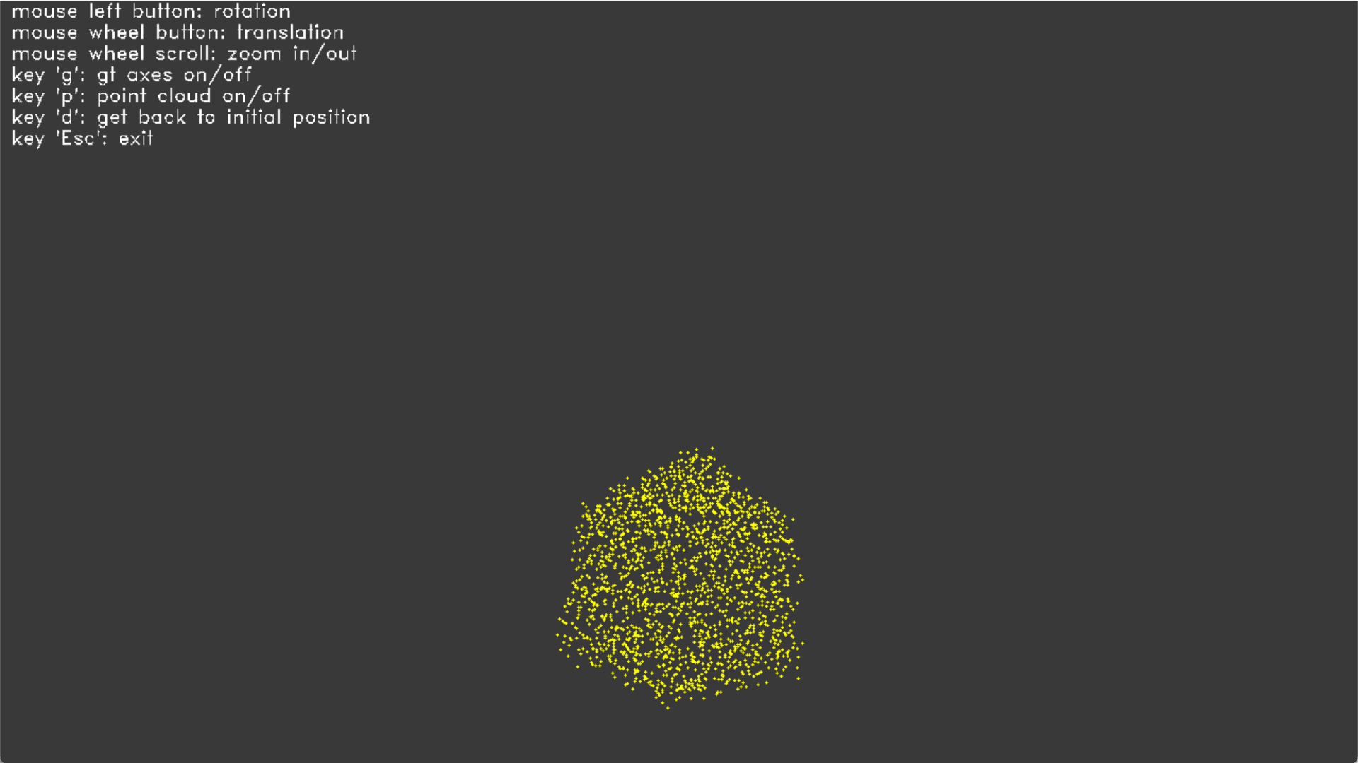
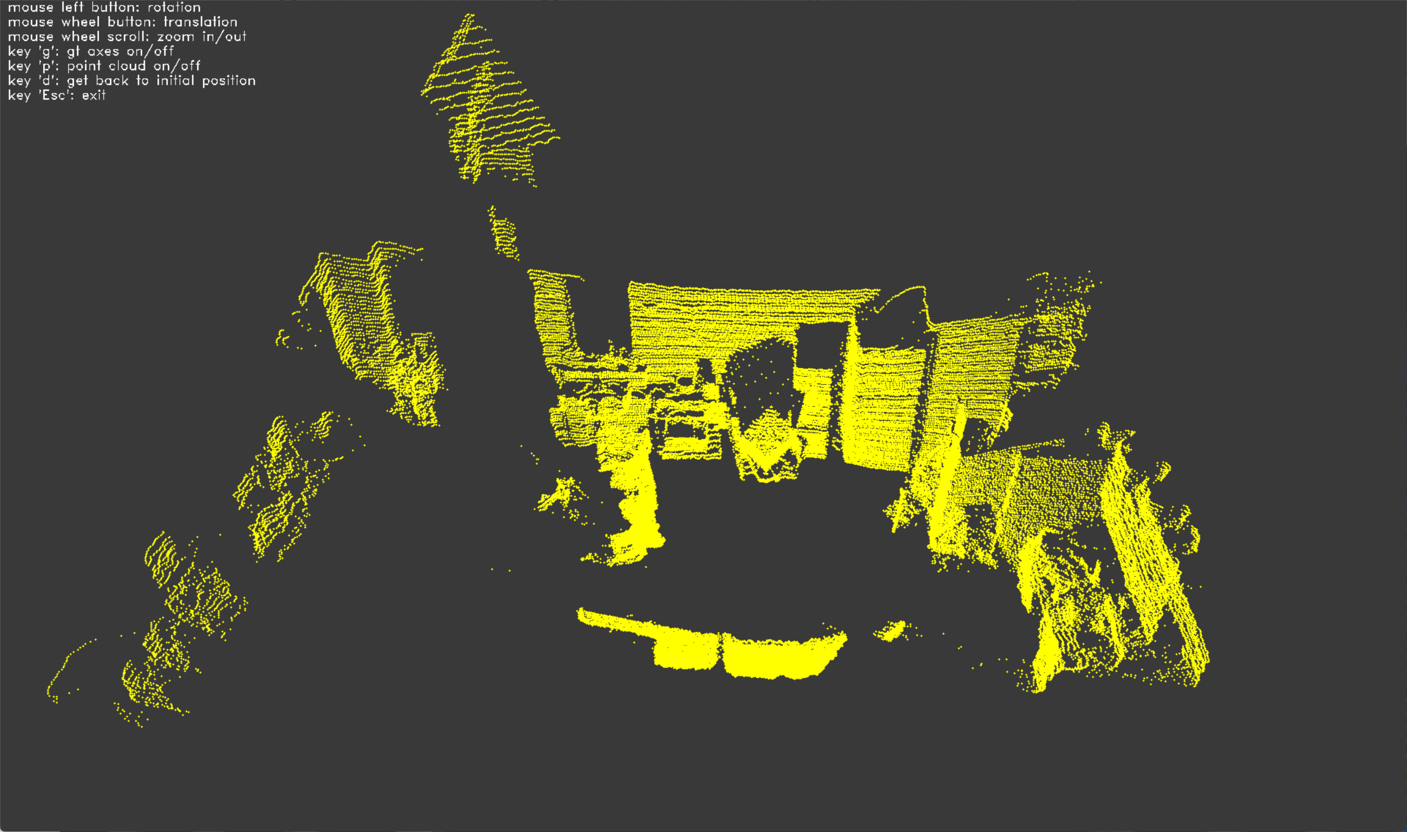
- Input image and point cloud
- Relative pose accuracy verification
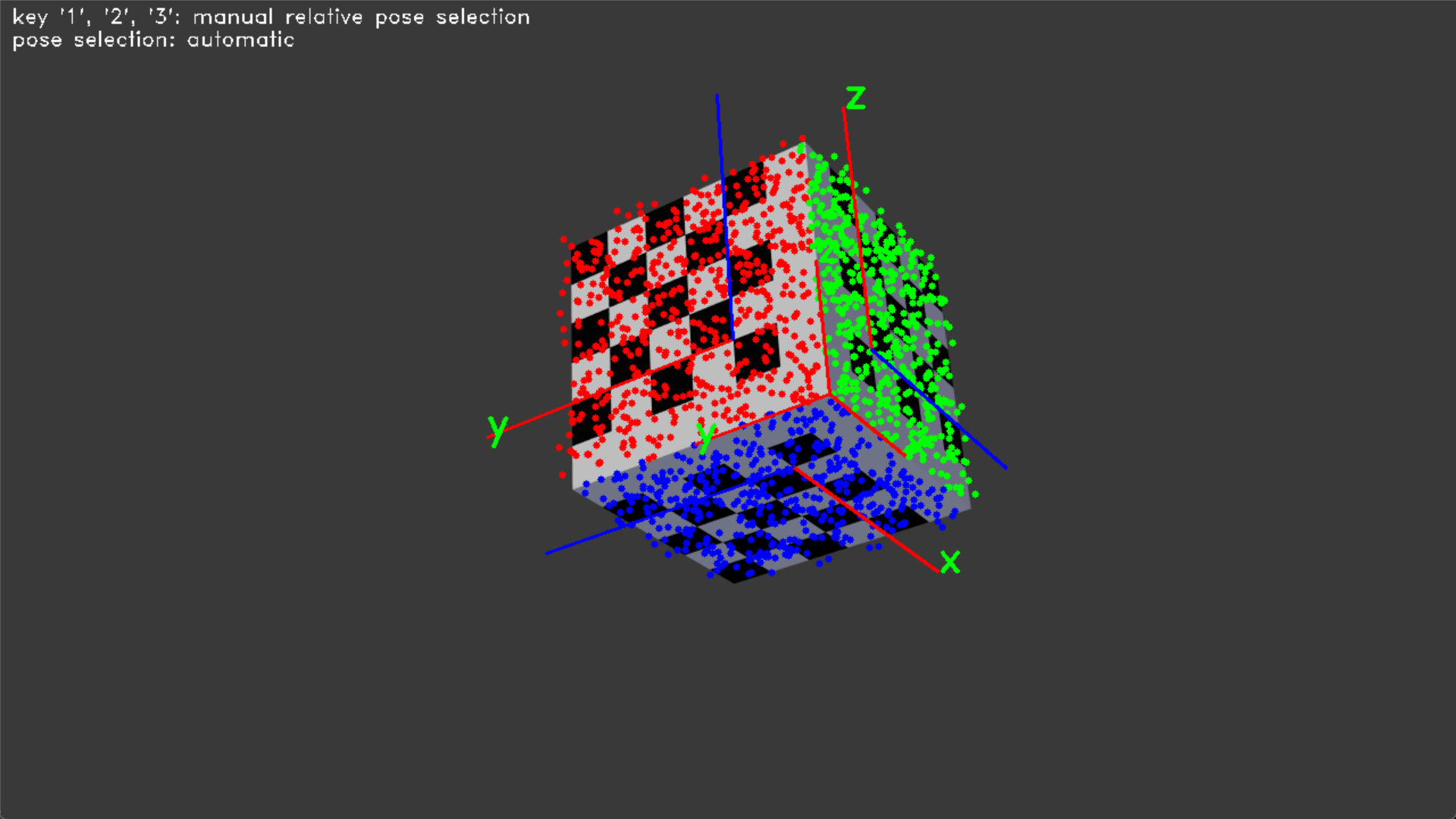
Each corresponding color of the point cloud is obtained from the image and represented as 3D points in the LiDAR coordinates.
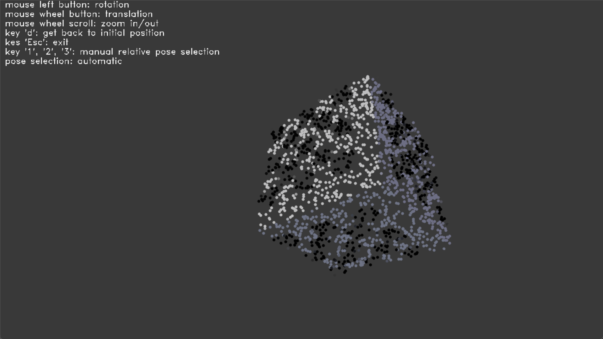
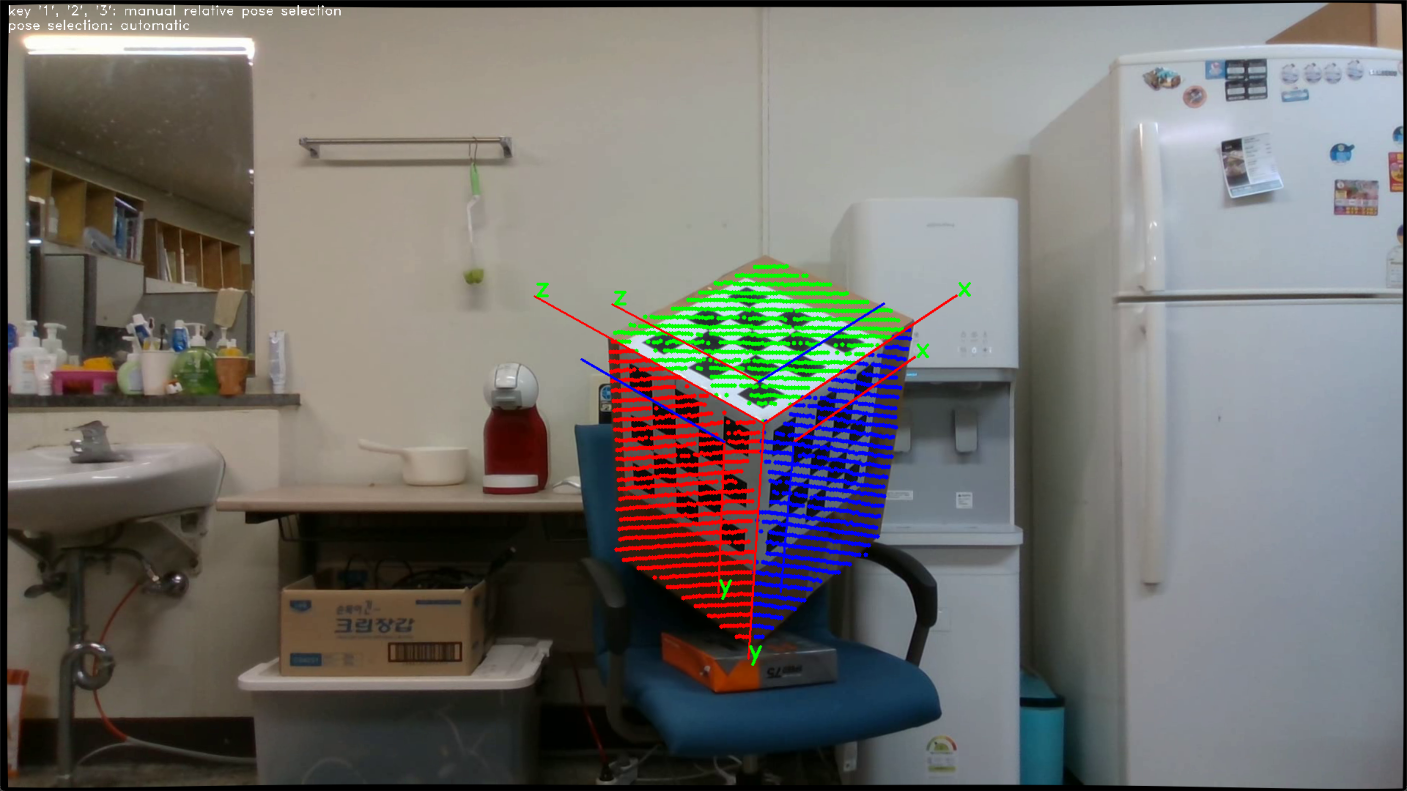
The point cloud is projected from LiDAR coordinates to image coordinates and overlaid with the image. 3D points on the target are classified into three planes by the estimated LiDAR pose. It is represented in RGB colors.


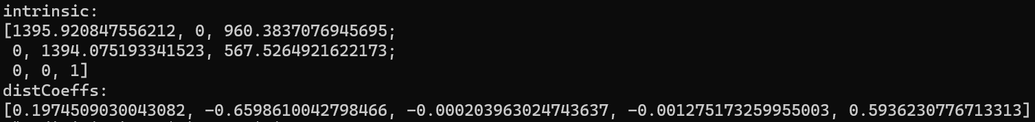
findCameraIntrinsicInReal() is an example of camera calibration.
- Camera intrinsic and distortion parameters

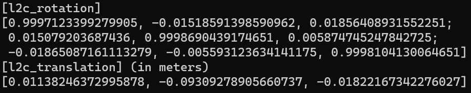
In calibrateInReal(), the 3D LiDAR-camera extrinsic calibration is tested in a real environment.
- The estimated relative pose (LiDAR-to-Camera)
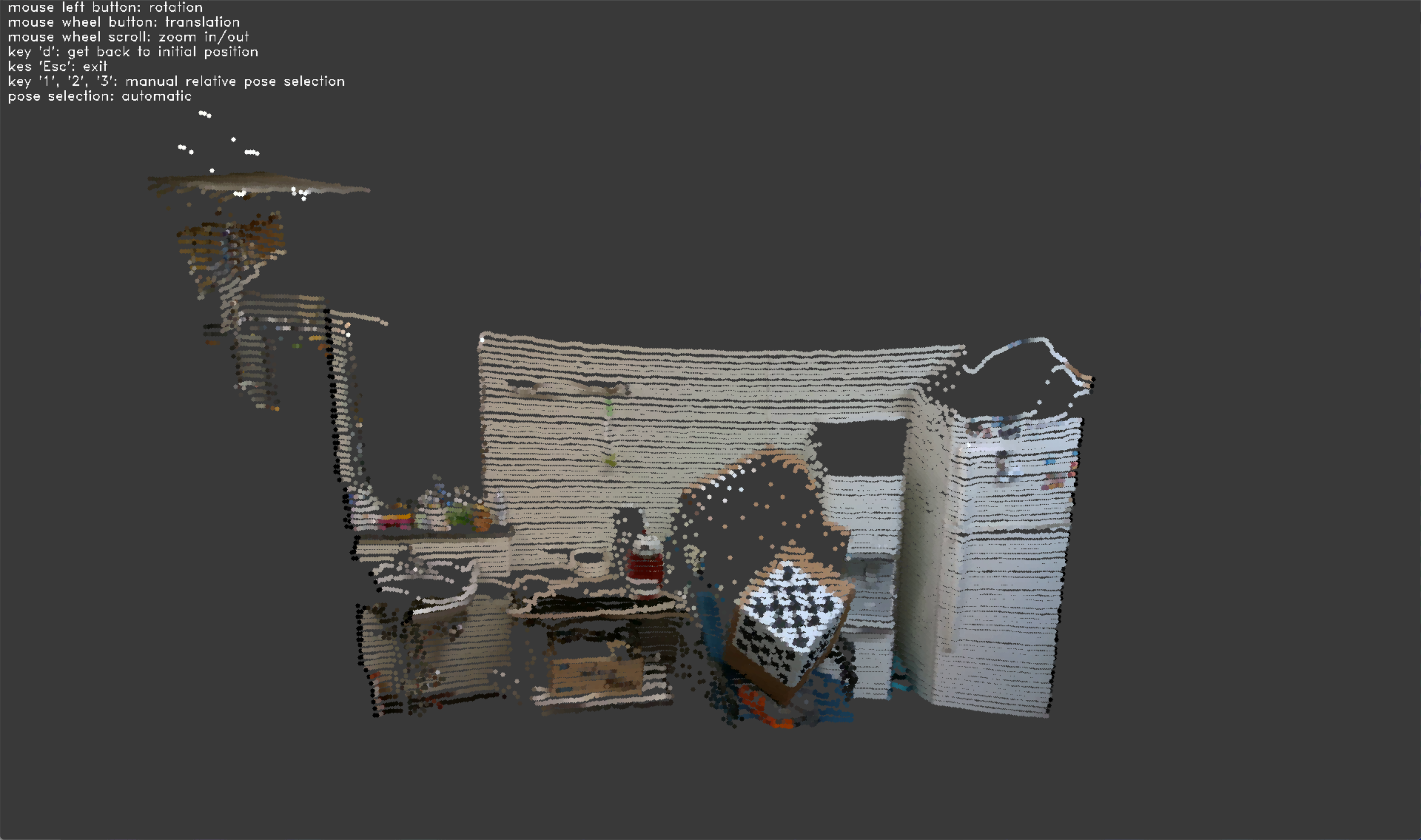
- Input image and point cloud
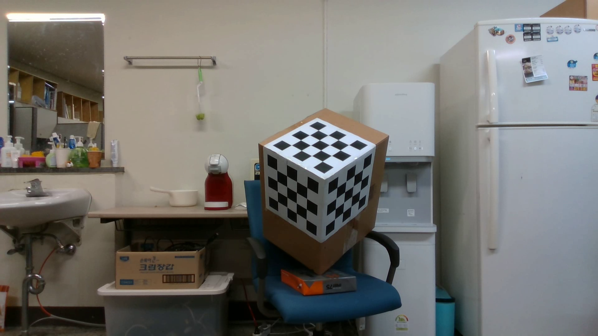
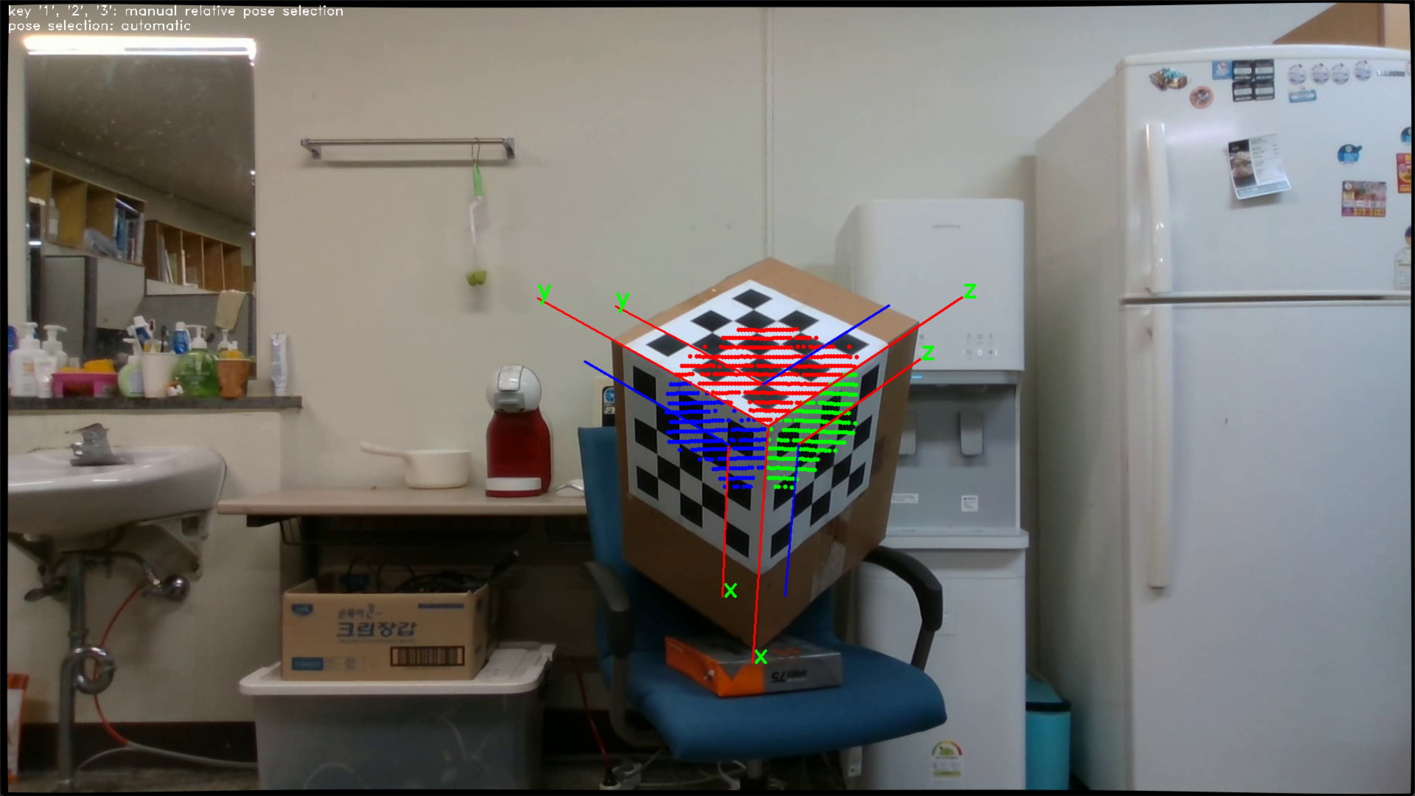
- Relative pose verification
Each corresponding color of the point cloud is obtained from the image and represented as 3D points in the LiDAR coordinates.
The point cloud is projected from LiDAR coordinates to image coordinates and overlaid with the image. 3D points on the target are classified into three planes by the estimated LiDAR pose. It is represented in RGB colors.
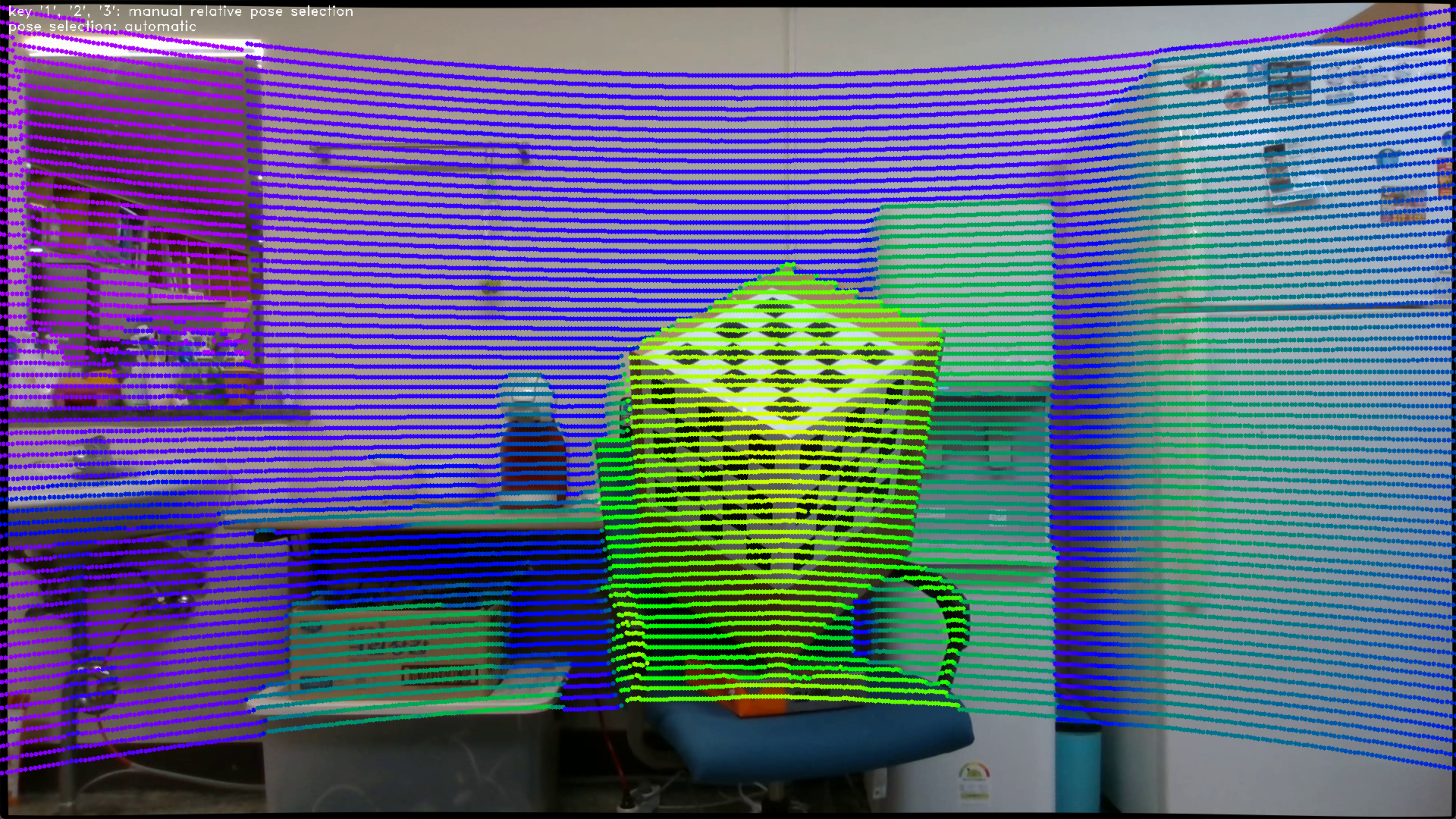
In the image below, the point cloud is colored according to distance.
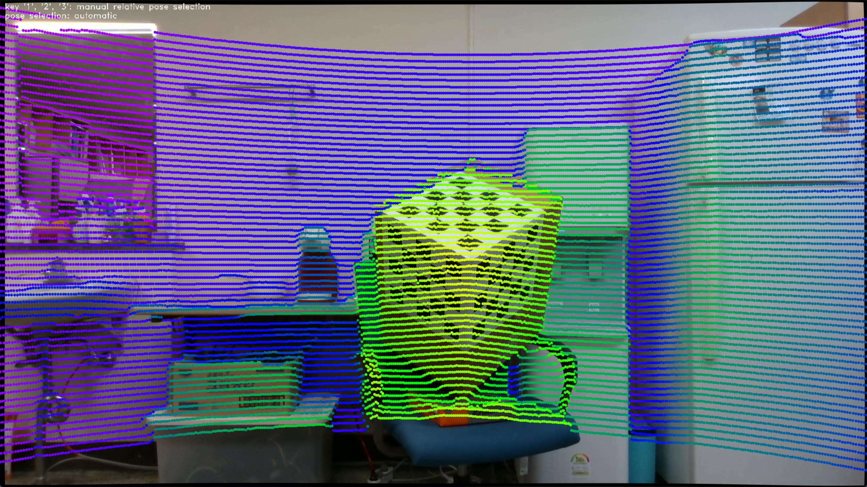
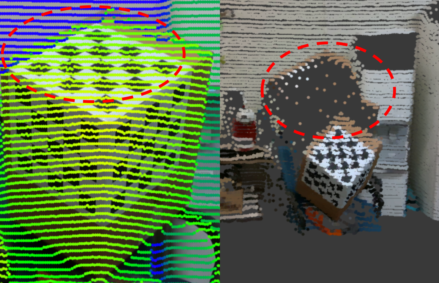
- Colorization problem
As the point cloud is rotated by relative pose, some 3D points overlap in the image coordinates. The blue points in the image on the left below actually represent a greater distance than the green points. In other words, the blue points should actually be colored with the color of the wall behind the box, but since the color behind the box cannot be seen in the image, it is colored with the color of the box. This problem arises from the colorization algorithm.


Our calibration method automatically selects the relative pose with the smallest rotation angle among the three possibilities.
For LiDAR-camera integrations with a large relative rotation angle, manual selection is required.
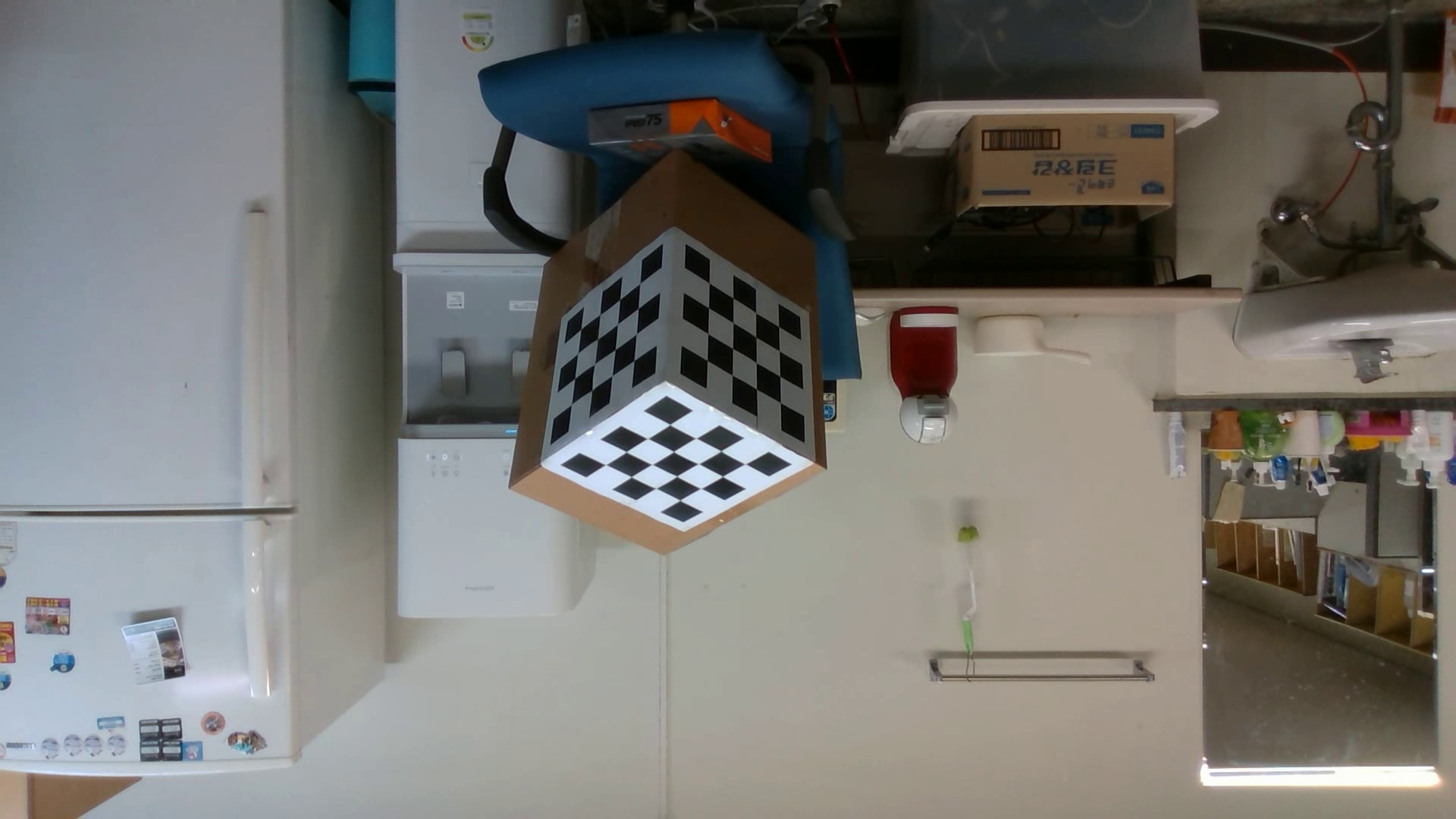
For example, calibrateInReal2() assumes the camera is mounted upside down. In other words, the input image is rotated 180 degrees around the camera's principal axis.
- Input image
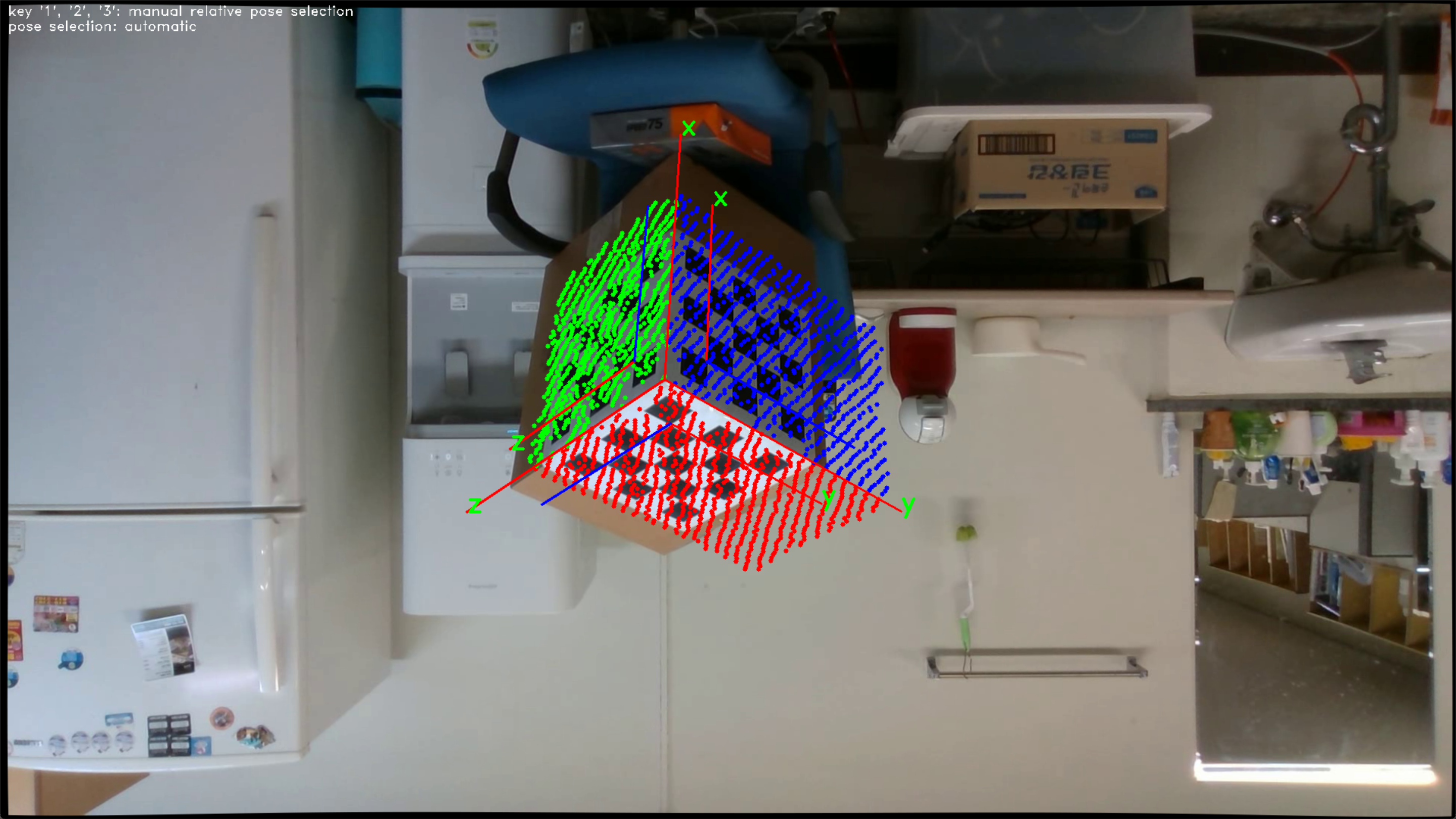
- The relative pose with the smallest rotation angle
The coordinate axes are correctly aligned with the target, but taking the image and point cloud into account, we can see that this result is incorrect.
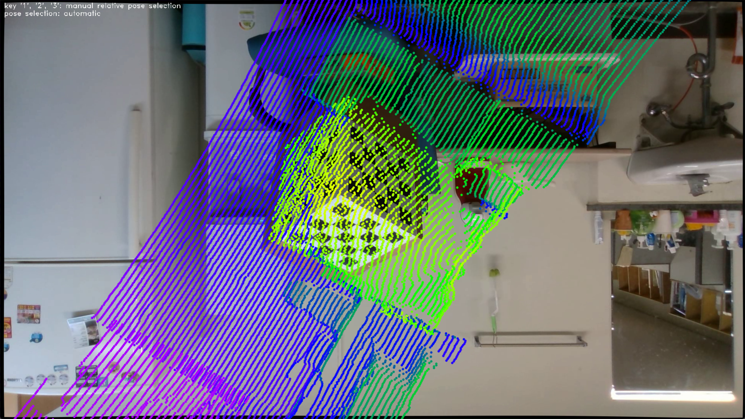
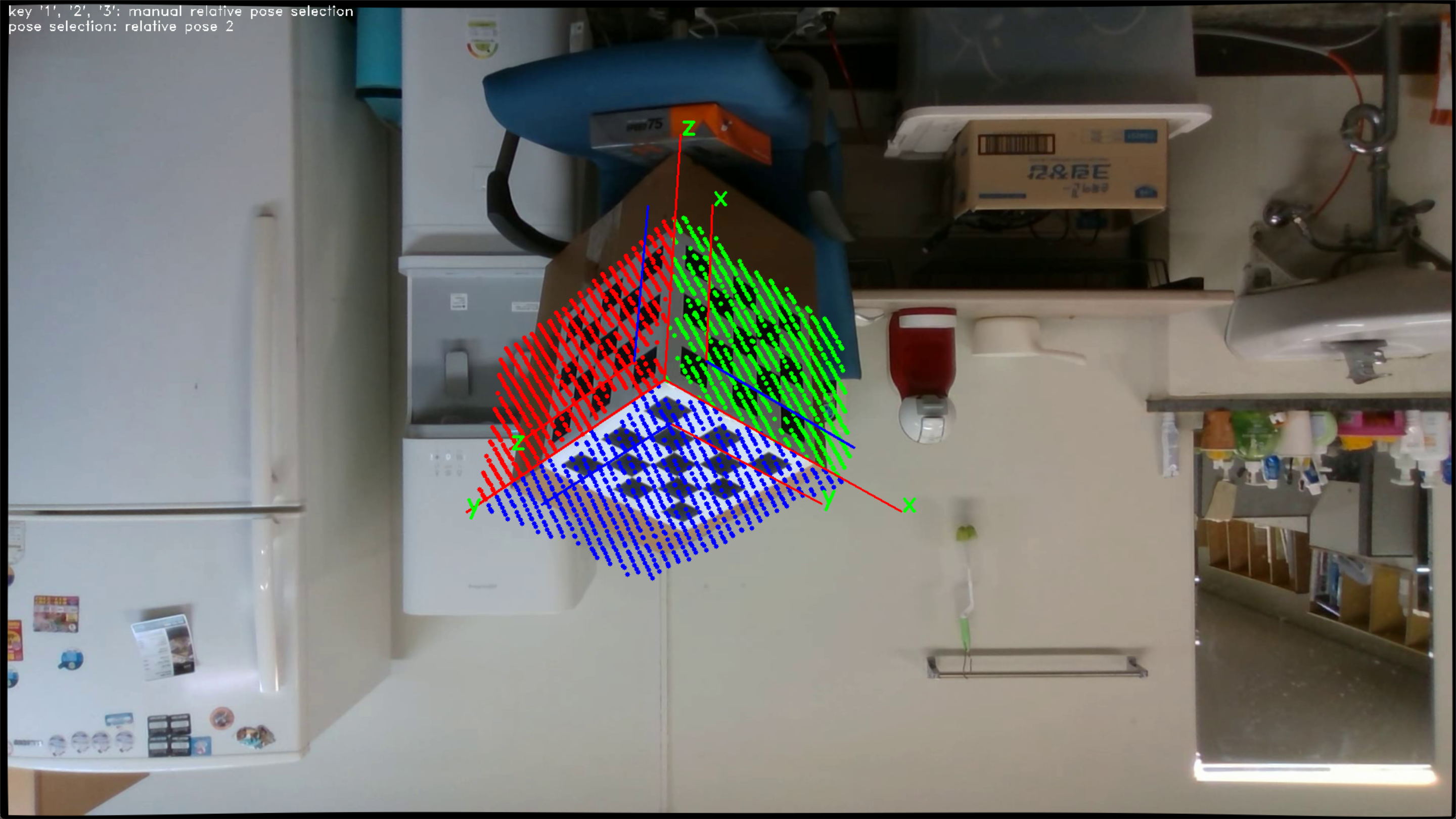
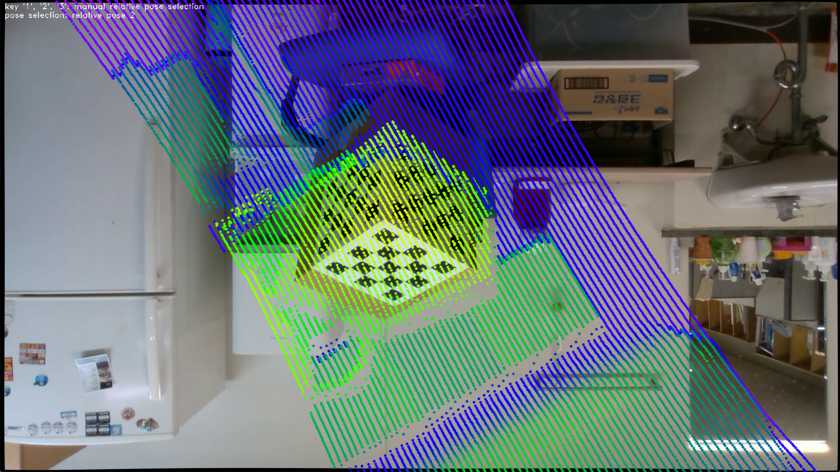
- Second relative pose for manual selection
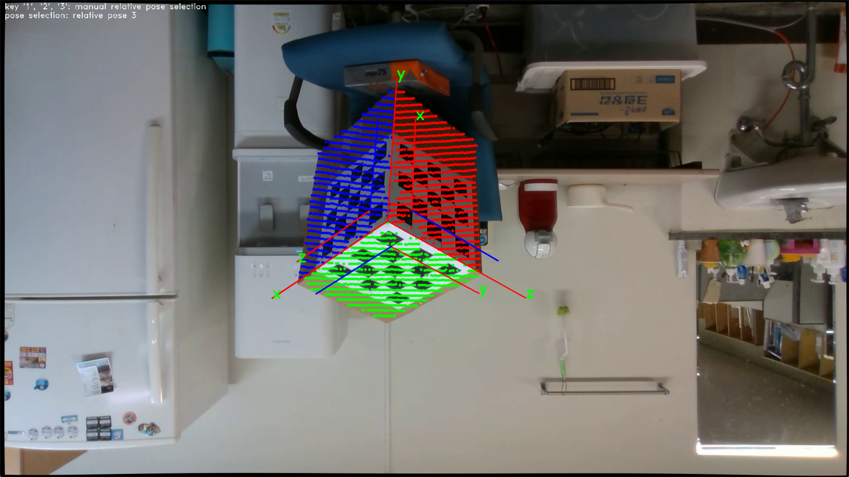
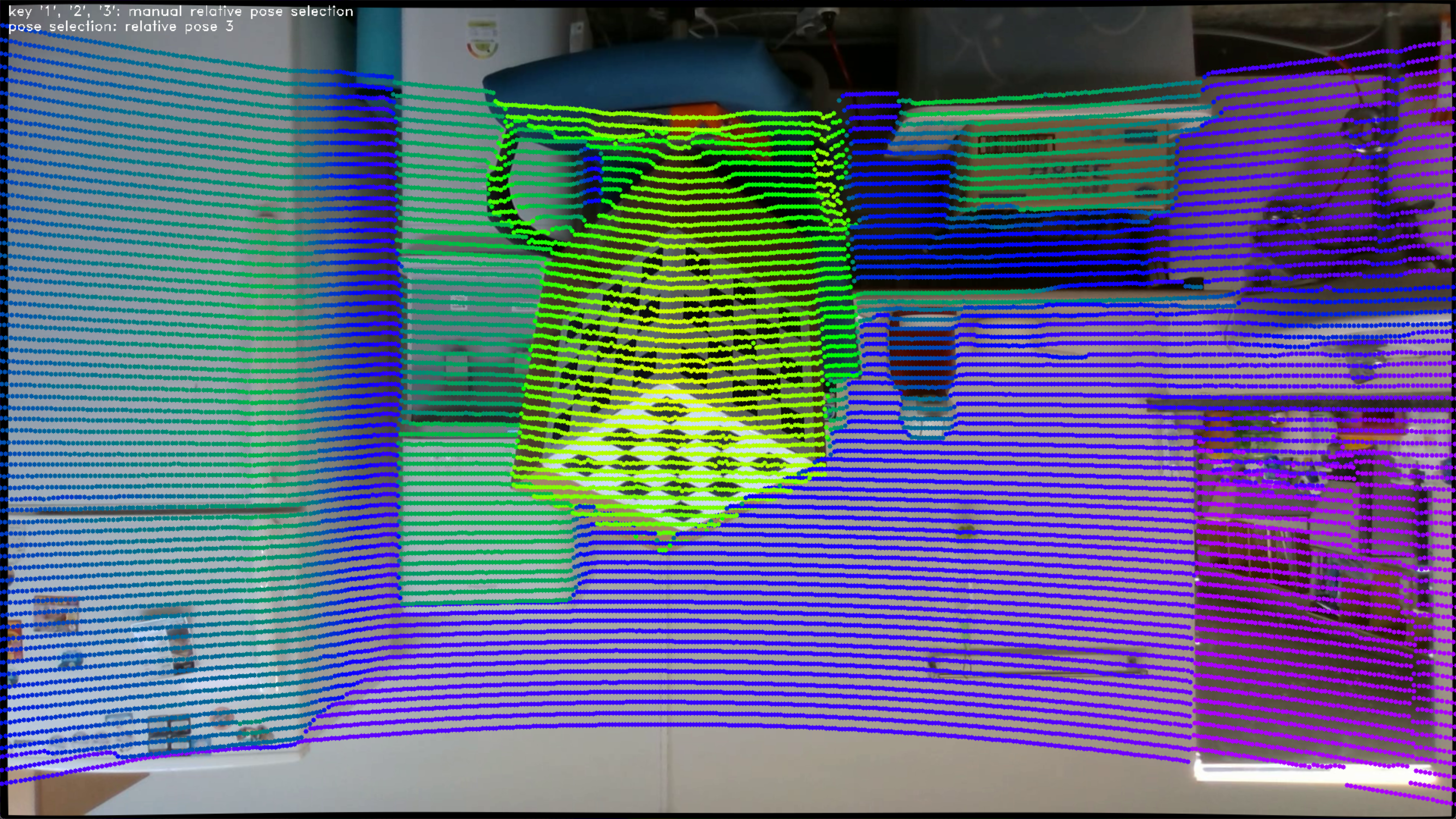
- Third relative pose for manual selection
- Conclusion
If the three planes of the target can be identified at each sensor, a fully automatic algorithm can be designed. Checkered patterns of three different sizes enable the camera to identify the three planes. Using a target with different plane sizes allows LiDAR to identify the three planes. However, these conditions require the sensor to fully observe the target. We think that these preparations make the use of the algorithm complex and cumbersome.
In our method, if possible, we recommend choosing a sufficiently large target and placing it close to the sensors. It doesn’t matter if the target is not fully observed in LiDAR’s FoV. Observation of many points leads to more accurate results.
The result below shows that the algorithm works even though only some points on the target are used.


The following is a BibTeX entry for the paper that you should cite if you use this algorithm.
@ARTICLE{10330001,
  author={Choi, Yeongyu and Park, Ju H. and Jung, Ho-Youl},
  journal={IEEE Transactions on Instrumentation and Measurement},
  title={Sample Pose Augmentation and Adaptive Weight-Based Refinement for 3-D LiDAR-Camera Extrinsic Calibration Using an Orthogonal Trihedron},
  year={2024},
  volume={73},
  number={},
  pages={1-14},
  doi={10.1109/TIM.2023.3336440}}