<<<<<<< HEAD
For any questions, please visit our website and forum to get more information.
On Windows, you can use
Cygwinas the GCC development environment.Cygwinis a large collection of GNU and open source tools which provide functionality similar to a Linux distribution on Windows. Click http://cygwin.com and download theCygwinpackage setup-x86.exe for your Windows platform.
-
32-bit
Cygwinis supported both for 32-bit Windows and 64-bit Windows. -
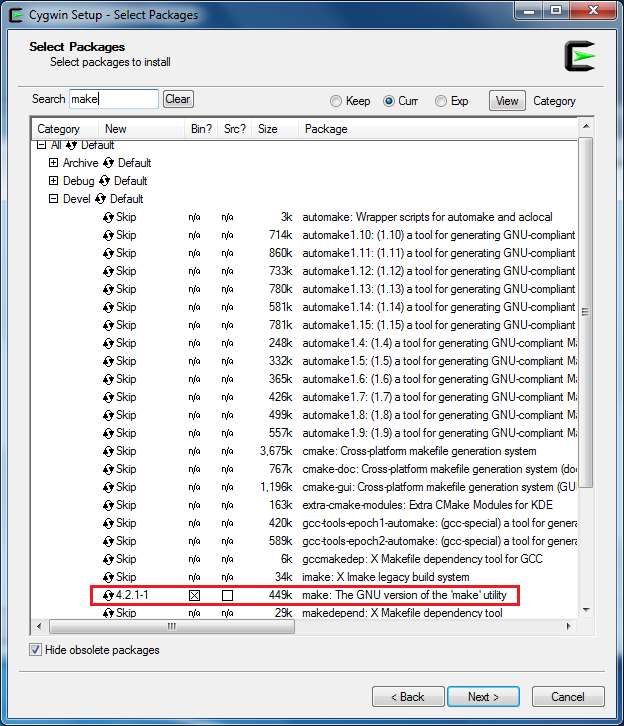
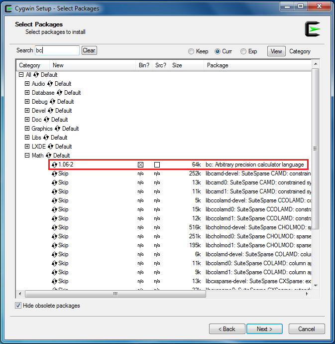
During the installation of
Cygwinpackage, includeDevel -> makeandMath -> bcutilities on the Select Packages page, as below shows.
Note: For Linux, refer to AN0400 Realtek Ameba-D Application Note.pdf to build the GCC development environment.
For Ameba-D, there are many types of chipsets available, such as RTL8720CS, RTL8721CSM, RTL8722CSM, RTL8720DN, RTL8720DM, RTL8721DM, and RTL8722DM. In addition, the chipsets can be embedded on Ameba-D DEV demo board, which is extended to various I/O interfaces. The corresponding HDK (Hardware Development Kit) documents are available, please contact RTK for further details.
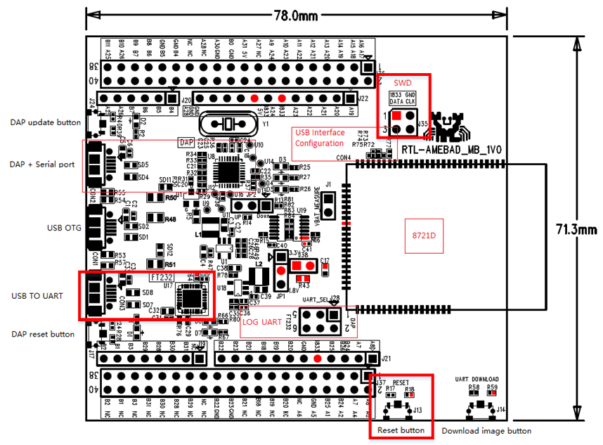
The hardware block diagram of Ameba-D demo board is shown below.
- USB TO UART: power supply and log print.
- The baudrate is 115200bps
- SWD: SWD interface, used to download images and debug with IAR.
- Reset button: reset Ameba-D to run firmware after IAR completes download.
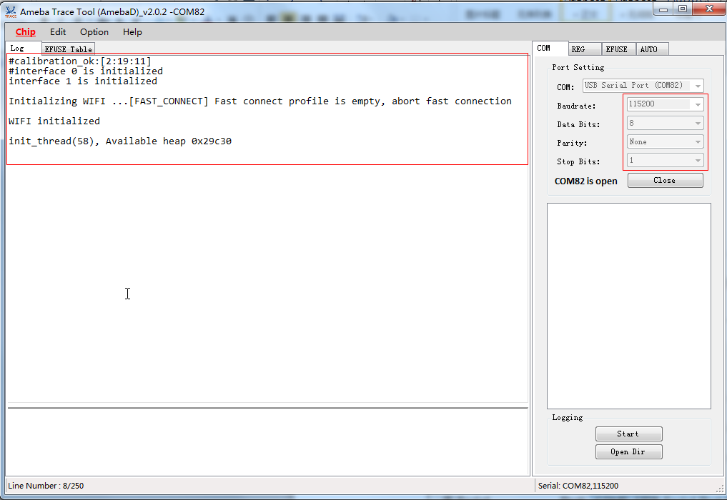
On Ameba-D board, FTDI Chip and FT232 can be used for the log console and debugger. To view the log console, make use of the terminal tool, such as
SecureCRT/teraterm/puttyand etc. We will take our internal tool as an example.
-
Select the corresponding serial uart configure communicate parameter and then open it.
-
Press the Reset button on Ameba-D board. Some messages can be found in the terminal.
The following steps are for first-time developer to build GCC project, under existing RTK SDK.
Building Code This section illustrates how to build SDK. First, you need to switch to GCC project directory. For Windows, open
Cygwinterminal and use$ cdcommand to change directory to KM0 or KM4 project directory of Ameba-D SDK.
Note: You need to replace the
{path}to your own SDK location, and addcygdriveprefix in front of the SDK location, so that Cygwin can access your file system.
cd /cygdrive/{path}/project/realtek_amebaD_va0_example/GCC-RELEASE/project_lp
cd /cygdrive/{path}/project/realtek_amebaD_va0_example/GCC-RELEASE/project_hp
Linux, open its own terminal and use $ cd command to change directory to KM0 or KM4 project directory of Ameba-D SDK.
cd /{path}/project/realtek_amebaD_va0_example/GCC-RELEASE/project_lp
cd /{path}/project/realtek_amebaD_va0_example/GCC-RELEASE/project_hp
To build SDK for normal image, simply use $ make all command under the corresponding project directories on Cygwin (Windows) or terminal (Linux).
KM0 project For KM0 project, if the terminal contains km0_image2_all.bin and Image manipulating end output message, it means that the image has been built successfully, as below shows.
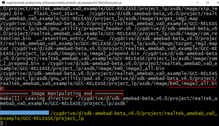
If somehow it is built failed, type
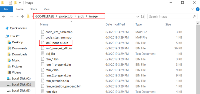
$ make cleanto clean and then redo the make procedure. After successfully built, the image file is located inproject/realtek_amebaD_va0_example/GCC-RELEASE/project_lp/asdk/image, as below shows.
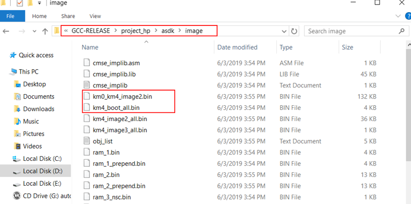
KM4 project For KM4 project, if the terminal contains km0_image2_all.bin and Image manipulating end output message, it means that the image has been built successfully, as below shows.

If somehow it built failed, type
$ make cleanto clean and then redo the make procedure. After built successfully, the image file is located inproject/realtek_amebaD_va0_example/GCC-RELEASE/project_hp/asdk/image, as below shows.
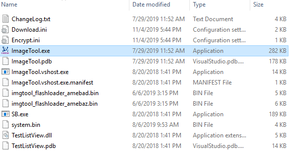
Realtek provides an image tool to download images on windows.
- Environment Requirements: EX. WinXP, Win 7 Above, Microsoft .NET Framework 3.5
ImageTool.exeLocation:SDK\tools\AmebaD\Image_Tool\ImageTool.exe
Assuming that the ImageTool on PC is a server, it sends images files to Ameba (client) through UART. To download image from server to client, the client must enter uart download first.
-
Enter into UART_DOWNLOAD mode.
- Push the UART DOWNLOAD button and keep it pressed.
- Re-power on the board or press the Reset button.
- Release the UART DOWNLOAD button.
Now, Ameba board gets into UART_DOWNLOAD mode and is ready to receive data.
-
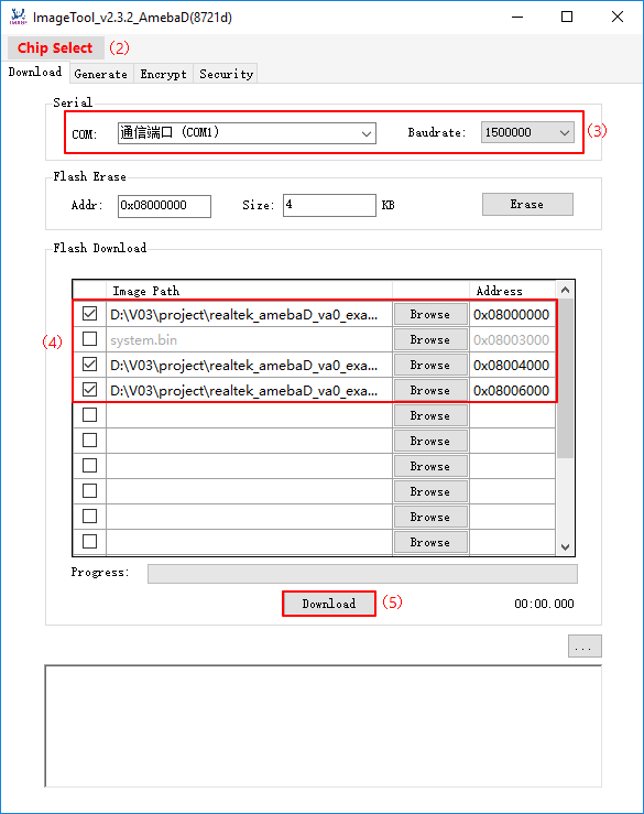
Click Chip Select(in red) on UI and select chip AmebaD.
-
Select the corresponding serial port and transmission baud rate. The default baudrate is 1.5Mbps (recommended).
-
Click the Browse button to select the images (km0_boot_all.bin/km4_boot_all.bin/km0_km4_image2.bin) to be programmed and input addresses.
- The image path is located in:
{path}\project\realtek_amebaD_va0_example\GCC-RELEASE\project_lp\asdk\imageand{path}\project\realtek_amebaD_va0_example\GCC-RELEASE\project_hp\asdk\image, where {path} is the location of the project on your own computer. - The default target address is the SDK default image address, you can use it directly.
- The image path is located in:
-
Click Download button to start. The progress bar will show the transmit progress of each image. You can also get the message of operation successfully or errors from the log window.
=======
For any questions, please visit our website and forum to get more information.
On Windows, you can use
Cygwinas the GCC development environment.Cygwinis a large collection of GNU and open source tools which provide functionality similar to a Linux distribution on Windows. Click http://cygwin.com and download theCygwinpackage setup-x86.exe for your Windows platform.
-
32-bit
Cygwinis supported both for 32-bit Windows and 64-bit Windows. -
During the installation of
Cygwinpackage, includeDevel -> makeandMath -> bcutilities on the Select Packages page, as below shows.
Note: For Linux, refer to AN0400 Realtek Ameba-D Application Note.pdf to build the GCC development environment.
For Ameba-D, there are many types of chipsets available, such as RTL8720CS, RTL8721CSM, RTL8722CSM, RTL8720DN, RTL8720DM, RTL8721DM, and RTL8722DM. In addition, the chipsets can be embedded on Ameba-D DEV demo board, which is extended to various I/O interfaces. The corresponding HDK (Hardware Development Kit) documents are available, please contact RTK for further details.
The hardware block diagram of Ameba-D demo board is shown below.
- USB TO UART: power supply and log print.
- The baudrate is 115200bps
- SWD: SWD interface, used to download images and debug with IAR.
- Reset button: reset Ameba-D to run firmware after IAR completes download.
On Ameba-D board, FTDI Chip and FT232 can be used for the log console and debugger. To view the log console, make use of the terminal tool, such as
SecureCRT/teraterm/puttyand etc. We will take our internal tool as an example.
-
Select the corresponding serial uart configure communicate parameter and then open it.
-
Press the Reset button on Ameba-D board. Some messages can be found in the terminal.
The following steps are for first-time developer to build GCC project, under existing RTK SDK.
Building Code This section illustrates how to build SDK. First, you need to switch to GCC project directory. For Windows, open
Cygwinterminal and use$ cdcommand to change directory to KM0 or KM4 project directory of Ameba-D SDK.
Note: You need to replace the
{path}to your own SDK location, and addcygdriveprefix in front of the SDK location, so that Cygwin can access your file system.
cd /cygdrive/{path}/project/realtek_amebaD_va0_example/GCC-RELEASE/project_lp
cd /cygdrive/{path}/project/realtek_amebaD_va0_example/GCC-RELEASE/project_hp
Linux, open its own terminal and use $ cd command to change directory to KM0 or KM4 project directory of Ameba-D SDK.
cd /{path}/project/realtek_amebaD_va0_example/GCC-RELEASE/project_lp
cd /{path}/project/realtek_amebaD_va0_example/GCC-RELEASE/project_hp
To build SDK for normal image, simply use $ make all command under the corresponding project directories on Cygwin (Windows) or terminal (Linux).
KM0 project For KM0 project, if the terminal contains km0_image2_all.bin and Image manipulating end output message, it means that the image has been built successfully, as below shows.
If somehow it is built failed, type
$ make cleanto clean and then redo the make procedure. After successfully built, the image file is located inproject/realtek_amebaD_va0_example/GCC-RELEASE/project_lp/asdk/image, as below shows.
KM4 project For KM4 project, if the terminal contains km0_image2_all.bin and Image manipulating end output message, it means that the image has been built successfully, as below shows.
If somehow it built failed, type
$ make cleanto clean and then redo the make procedure. After built successfully, the image file is located inproject/realtek_amebaD_va0_example/GCC-RELEASE/project_hp/asdk/image, as below shows.
Realtek provides an image tool to download images on windows.
- Environment Requirements: EX. WinXP, Win 7 Above, Microsoft .NET Framework 3.5
ImageTool.exeLocation:SDK\tools\AmebaD\Image_Tool\ImageTool.exe
Assuming that the ImageTool on PC is a server, it sends images files to Ameba (client) through UART. To download image from server to client, the client must enter uart download first.
-
Enter into UART_DOWNLOAD mode.
- Push the UART DOWNLOAD button and keep it pressed.
- Re-power on the board or press the Reset button.
- Release the UART DOWNLOAD button.
Now, Ameba board gets into UART_DOWNLOAD mode and is ready to receive data.
-
Click Chip Select(in red) on UI and select chip AmebaD.
-
Select the corresponding serial port and transmission baud rate. The default baudrate is 1.5Mbps (recommended).
-
Click the Browse button to select the images (km0_boot_all.bin/km4_boot_all.bin/km0_km4_image2.bin) to be programmed and input addresses.
- The image path is located in:
{path}\project\realtek_amebaD_va0_example\GCC-RELEASE\project_lp\asdk\imageand{path}\project\realtek_amebaD_va0_example\GCC-RELEASE\project_hp\asdk\image, where {path} is the location of the project on your own computer. - The default target address is the SDK default image address, you can use it directly.
- The image path is located in:
-
Click Download button to start. The progress bar will show the transmit progress of each image. You can also get the message of operation successfully or errors from the log window.
51fb2a6da99df080983b8a2af5ac2593d74e8470