An ESP32 based, Portal themed e-ink calendar that can run on AAA batteries for years, with optional weather integration through OpenWeatherMap.
This project was inspired by Reddit user u/feefifofeddit who made a prototype of a Raspberry Pi-powered Portal calendar. Unfortunately the display they used has been discontinued, and I wanted a battery powered and wall mountable version, so I designed my own based on the ESP32 platform with the goal of being as low-power and game accurate as possible.
By default, chamber hazard icons from both Portal and Portal 2 are shown below the current date. Portal icons are shown for day 1 through 16, while Portal 2 icons are shown for day 17 through 31.

With the weather feature enabled, the chamber hazard icons are replace by either a 5-day or 12-hour weather forecast provided by OpenWeatherMap that shows the average weather condition, the high & low temperatures, the chance of rain, or the humidity, at your preference.

The weather icons are based on the designs by Lukas Bischoff and Erik Flowers, available here.
-
Waveshare 7.5" 800x480 E-Ink display
Available directly from Waveshare or from Amazon. The display itself is the Good Display GDEW075T7, Waveshare just resells it and gives you a breakout board.
Make sure you buy the bare display with breakout board. Don't buy the one preinstalled in a case. Don't buy the Black/White/Red version of this display either, just the standard Black/White one.
This display is intended only for 2-color greyscale (full black or full white, with no grey levels). However, this code does some hacks to it to make it support 4-color greyscale for better antialiasing. I didn't invent this technique, the GxEPD2 project among others does the same thing. The downside of doing this, however, is that results can vary from display to display. The greyscale levels may not look as good on your particular display as they do on mine. I've tried to design the graphics with that in mind so that the grey level isn't critical to get things to look good, but I've only tried this on two of these displays, and I can't guarantee yours will look perfect.
-
EzSBC ESP32 breakout board
Available here or here. This will run on any ESP32, but this particular board is perfect for alkaline battery power due to its efficient voltage regulator and flexible input voltage. If you use a different board, you will need to modify the case and come up with your own power solution.
-
4xAAA battery holder
Pretty much all of them will work. This is a good one.
-
9x M3x8 cap head screws
Before you begin, note that this project does require soldering and cutting the included display wiring harness. Since it's the most expensive part of the project, I recommend testing your display first before cutting anything so you can easily return it if it's defective. The breakout board comes with pin headers you can solder and directly connect to the stock wiring harness, so I highly recommend skipping down to step 5 and connecting everything up to make sure the dispaly works first. Once you've done that, desolder the pin headers from the breakout board and follow these instructions from the beginning.
-
Print front.stl and back.stl. Once those are done you can start putting things together, and get cover.stl printing while you work. Print with a 0.2mm layer height, other than that print settings really don't matter that much.
-
Remove the protective film on the front of the e-ink display if it has one (there should be a colored tab in one corner you can pull).
-
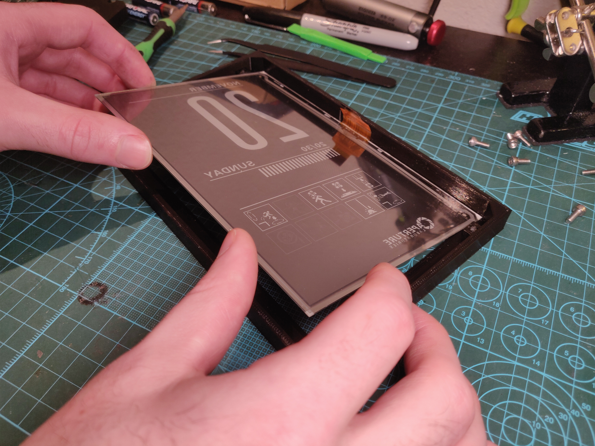
Insert the display into front.stl, oriented so the ribbon cable goes into slot on the side. The easiest way to do this is to gently pre-bend the ribbon cable, then slide the display in from the opposite side.
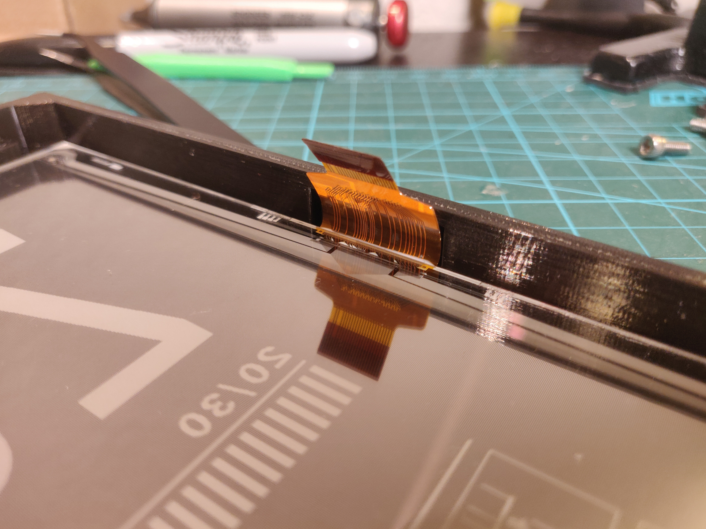
This should go without saying, but the display and the ribbon cable connection are very fragile. Here's a close-up of how the ribbon cable should seat in the slot.
Recent versions of this display have a slimmer ribbon cable than shown in these pictures, however it should be the same length and have the same pinout, and is fully compatible.
Once it's inserted, make sure the display is sitting flat and that the edges of the display are flush with the edges of the case on the top and bottom.
-
Insert back.stl on top of the display, flat side down, being careful that the ribbon cable doesn't get snagged when sliding in the slot on the side.
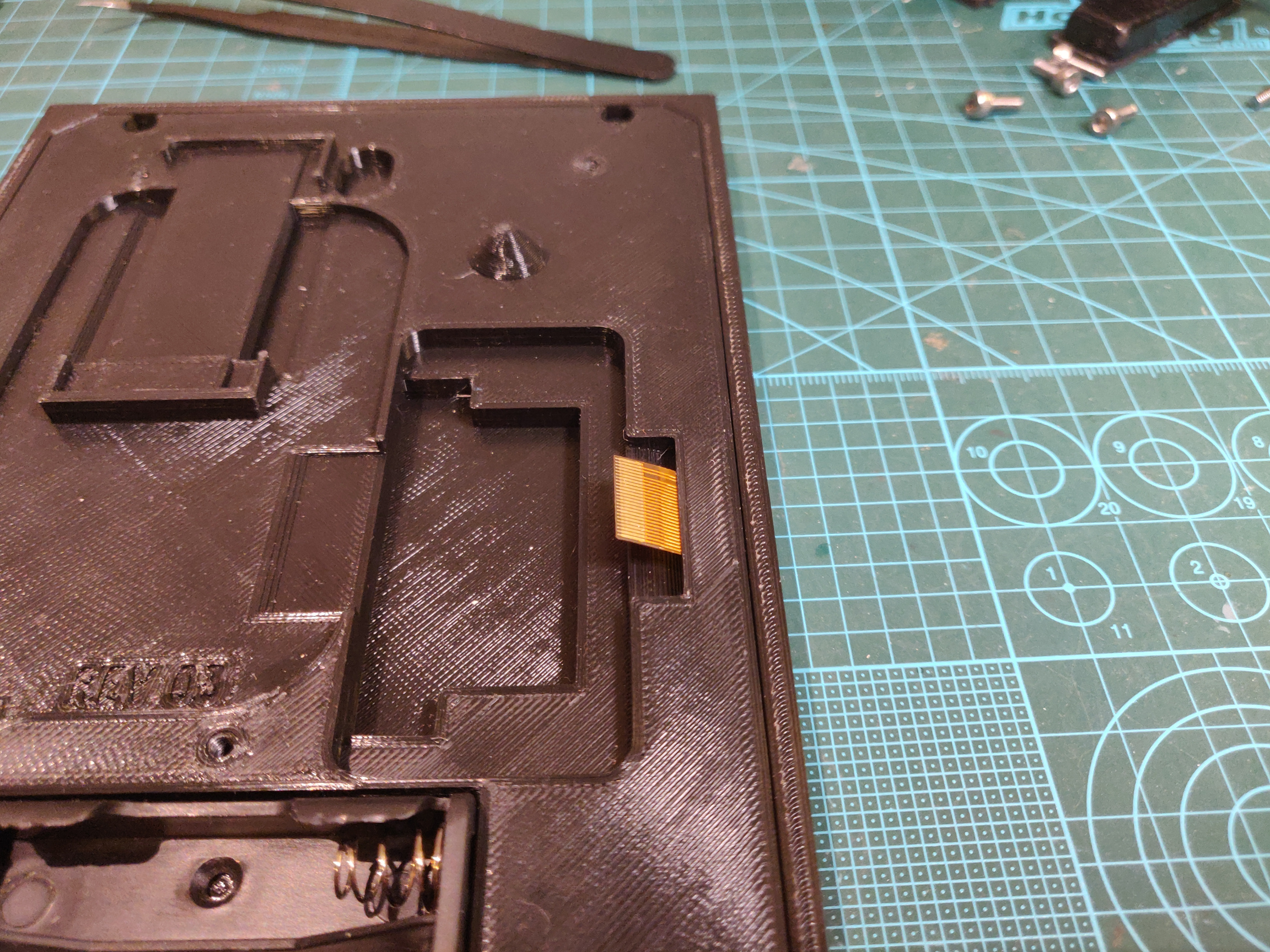
The back cover should be flush with the edges of the front cover. If it's not, the display may not be seated correctly in the front cover. Don't try to force it, remove the back cover and re-seat the display.
Once the back cover is installed, you can secure it with an M3x8 screw in each corner.
-
Insert the e-Paper Driver HAT into the slot by the ribbon cable and clip the ribbon cable into the connector. Make sure you get it fully seated in the connector, and make sure to latch it closed, otherwise the display may not work when you try to power it on. Also, make sure the Display Config switch is in the B position, and the Interface Config switch is in the 0 position.
-
Now the fun part begins, cutting wires to length and soldering them to the ESP32. Note the colors listed below are the ones used in the wiring harness I got, yours is probably the same but it may be different if Waveshare changed it.
Note that the PWR pin does not exist prior to revision 2.3 of the waveshare driver board. If you have revision 2.2 or earlier, ignore that pin in the chart below. The firmware will work with both, no other changes are needed.
e-Paper HAT ESP32 VCC (Grey) <-> 3.3v GND (Brown) <-> GND DIN (Blue) <-> IO13 CLK (Yellow) <-> IO14 CS (Orange) <-> IO15 DC (Green) <-> IO23 RST (White) <-> IO33 BUSY (Purple) <-> IO27 PWR (Red) <-> IO32 -
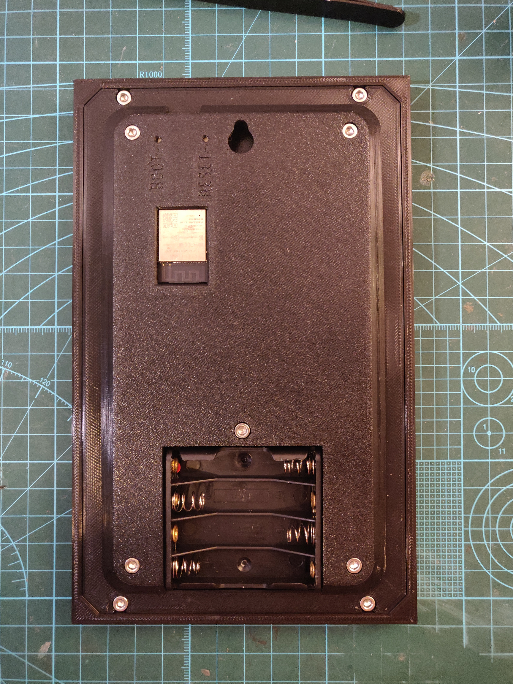
Glue in the battery holder (I used JB weld plastic bonder), and solder the red and black wires to the Vin and GND pins on the ESP32.
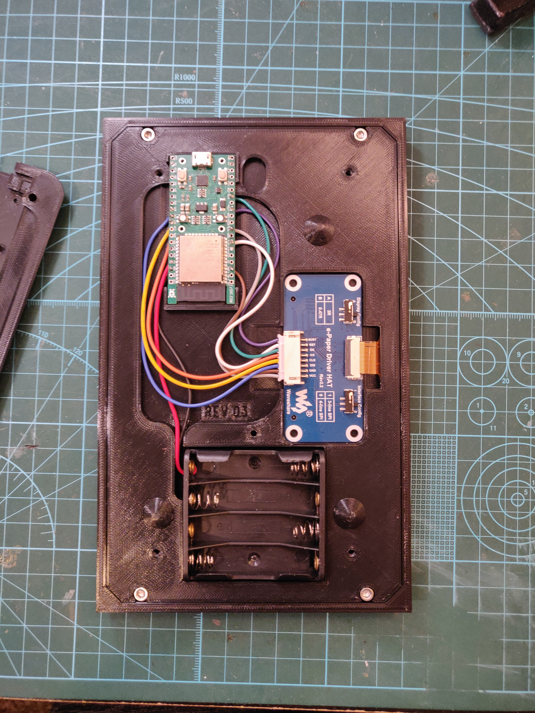
Here's what everything should look like once wired up. Note that this photo shows the older waveshare driver board without PWR pin.
-
Make sure all the wires are inside the recess on the back cover so they aren't pinched, and make sure the ESP32 is seated in its recess. Then you can install cover.stl and secure it with an M3x8 screw in each corner, and one in the center above the battery holder.
There's no point in putting the batteries in yet since the ESP32 still needs to be programmed.


This project requires the following dependencies to be installed through the library manager
- ArduinoJson 6.21.4
- ESPAsyncWebSrv 1.2.7
You also need to install the ESP32 board package 2.0+. Go to File -> Preferences and add the following URL to Additional Boards Manager URLs
https://raw.githubusercontent.com/espressif/arduino-esp32/gh-pages/package_esp32_index.json
Then, go to Tools -> Boards -> Boards Manager... and search for esp32

Then, select ESP32 Dev Module for your board.

Once that's selected you'll see a bunch of other options show up in the Tools menu.

The partition scheme will need to be changed to allow the app to fit. Other than that, the rest of the options should already be what you want, but make sure they match these settings.
| Option | Value |
|---|---|
| CPU Frequency | 240 Mhz (WiFi/BT) |
| Events Run On | Core 1 |
| Flash Frequency | 80Mhz |
| Flash Mode | QIO |
| Flash Size | 4MB (32Mb) |
| Arduino Runs On | Core 1 |
| Partition Scheme | Huge APP (3MB No OTA/1MB SPIFFS) |
| PSRAM | Disabled |
| Upload Speed | 921600 |
To enable debug logs, choose Info for Core Debug Level. Otherwise, leave it set to None.
Now you can just flash it like any other arduino.
Assuming you already have PlatformIO installed, there shouldn't be anything else you need to do before building and flashing. Just select Build or Upload under the EzSBC environment.
To enable debug logs, add -DCORE_DEBUG_LEVEL=3 as a build flag in platformio.ini (it should already be there as a line you can uncomment).
The internal clock in the ESP32 is very inaccurate with a specified inaccuracy of 5%, which corresponds to 72 minutes per day. This is obviously useless for long-term timekeeping so an external clock is required. One solution would be to use an RTC module like a DS3231, but that still requires an external time source for initialization. Given that, I decided to just ditch that extra cost and require a Wi-Fi connection for daily NTP time syncing, which would be required for OpenWeatherMap anyway if you decide to use it. The default NTP servers are pool.ntp.org and time.google.com, but they can be changed if you want.
The Wi-Fi connection is also used to lookup information for the timezone you provide, using the timezoned service from the ezTime project. The default timezoned servers are the original one at timezoned.rop.nl and mine at timezoned.jacobjordan.tech. This does introduce a failure point if these services both go down, and if that's something you're worried about you can host your own timezoned service. The original PHP code is available in ropg's repository, and my Rust rewirite is availble here.
Like I mentioned in the Bill of Materials section, I'm doing some hacky stuff with the e-ink display to get it to support 4-color greyscale, both for antaialising and so the inactive chamber icons look better. The specifics on how all this works are outside the scope of this readme, but if you'd like to learn the basics of how e-ink displays work I recommend watching Applied Science's video.
A consequence of this is that I've had to write my own simple 2-bit drawing library for this project, since Adafruit GFX doesn't support that and I don't know of any other libraries that do. The low-level code for drawing to the display is located in DisplayGDEW075T7.cpp, which includes low-level drawing commands like setPx, drawVLine, drawHLine, fillRect, and strokeRect, but also more advanced commands like drawImage, drawText, and drawMultilineText, which I'd like to explain a bit further in case you want to modify the icons or fonts used in this project.
All of the bitmap and font resources are in the resources directory, which can be compiled to C header files using build_image.py and build_font.py respectively. I chose to simply compile resources to C code that can be embedded into the firmware instead of loading them from the ESP32's SPIFFS because it greatly simplifies the flashing process.
The build_image.py script can take in any image format supported by PIL and will output a 2-bit-per-pixel run-length encoded C header file of the same name that can be included and drawn to the display. All of the images used in this project are inclued in this repo both as the original GIF images and the compiled C header files.
The build_font.py script will take in TrueType or OpenType fonts and output a bitmap font rendered at the specified size to a C header file, using the same encoding format as build_image. Look at build_fonts.sh for usage examples. Unlike for the images, I haven't included the source fonts in this repository because they are the original, proprietary fonts used in the Portal games. If you want to rebuild those fonts, it's up to you to find them online.
- Add compatibility with Rev2.3 Waveshare driver board.
- Slightly adjust VCOM_DC for a bit better contrast.
- Compress images with simple run-length encoding to save a bit of flash.
- Draw progress bar with vector draw commands instead of an image to save a bit more flash.
- Add STEP file.
- Add the ability to setup the calendar through a web app instead of changing the firmware and re-flashing. There is no longer any need to edit config.h unless you need to change pin assignments or other advanced settings.
- This update changes the partition scheme. If you're building with Arduino IDE, read through the Firmware section again and update your build options.
- Add ability to toggle between the weather and chamber icon display using a button on GPIO0.
- Frame REV 04: Fix the boot and reset buttons being labeled backwards, and call the boot button 'mode' since it does something now. If you have frame REV 03 and want to fix this, you only need to print cover.stl since the front and back parts are compatible with it.
- All code in this repository is licensed under the MIT license.
- All images in this repository are licensed under the Creative Commons Attribution-NonCommercial license.
- All STL and 3D CAD files in this repository are licensed under the Creative Commons Attribution-ShareAlike license.