Volvo 240 Digital Dash Project. Designed to use existing dash connectors (circular connectors w/ 2mm pins, vehicle speed sensor (VSS) connector, and various spade connectors) to minimize extra wiring effort and installation of superfluous sensors.
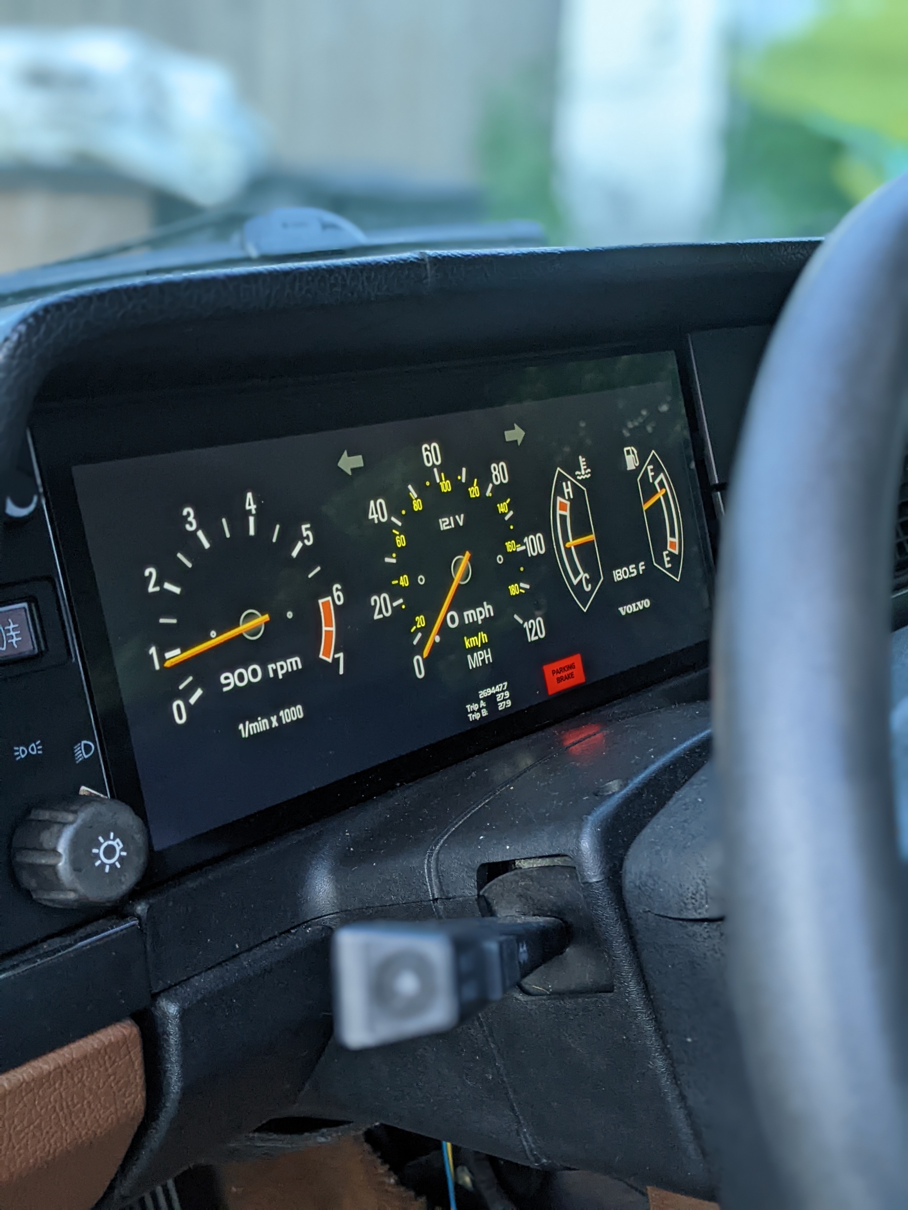
One of the main goals of the project was to use the existing Volvo 240 connectors. The only additional connectors and wiring needed are for sensors that weren't available on the stock main dash (oil pressure, oil temperature, vacuum/boost pressure, etc). Dash lights (low oil pressure, battery voltage, parking brake,high beams, etc) are functional as well as turn indicators. Fuel level and coolant temperature are functional. The hardware supports the addition of common accessory sensors such as oil pressure, oil temperature, manifold absolute pressure, and ambient temperature.
Different Volvo dash styles can be displayed:


The raspberry pi 4 supports 2 HDMI outputs so a second screen can be added where normal 52mm accessory gauges would have been placed:

Touch screen controls on this screen can be used to changed between dash layouts and also to reset trip odometers. The style of the accessory gauges reflects the style of the main dash layout.

This directory contains the hardware and software components that makeup the dash. There are also various visual/graphical assets that are used in the dash app.
This directory contains the Qt app and related unit tests. It is advised to use QtCreator to edit and compile the app. Using QtCreator to QtDash/VolvoDigitalDashModels/subdirs.pro will load both the app and the unit tests. The app is written using C/C++ for interfacing with the various sensors and QML for the UI.
This directory contains the hardware that has been designed for this project. Most of the PCBs have been designed using Eagle 7.7 as this is what I am most familiar with. The future of Eagle is questionable as an open source/free tool, so Kicad 6 will be used more and more as I become more familiar with it.
This directory contains the schematics and board files for the PCB that directly interfaces with the Raspberry Pi 40 pin header. The board is split up into a low voltage (3.3/5V) that is powered from the Pi header and a high voltage (car battery voltage 8-16V) that is powered from the 240 ignition switch via the VSS connector. The high voltage side is optically isolated from the low voltage side using optoislators.
This directory contains the schematics and board files for the cold start tolerant power supply design based around the LM3488. The input range is ~3V-24V and the output is ~5V rated at 3A. During bench testing the input power needs to be above 5V when first powering up, and then could drop to ~3V while still continuously powering the Pi. This is a little overkill as the battery voltage during cranking only momentarily drops to 3V-4V before recovering very quickly to >10V.
This directory contains the .stl files for mounting the HSD123KPW2-D10 12.3" TFT LCD using the stock 240 dash mounting holes. These mounts will put the screen flush with the surrounding dash. The mounts and all other 3D modeling/CAD has been done using Onshape. Included in the public OnShape document are models of the main PCB, HSD123KPW2-D10 LCD, screen mounts, etc.
This directory contains SPICE simulations of various circuits used in the dash. This is more of a scratchpad than it is a serious attempt at accurate real-life simulations.
This directory contains the schematics and board files for the tach signal adapter. This board takes the high voltage pulses (>30V on my 88 245) and converts them to a square wave that can be used by the dash software to calculate RPM. The high voltage pulses are optically isolated from the dash/pi side to prevent any unwanted noise or damage to the pi or other hardware.
This directory contains the schematics and board files for the VSS signal adapter. This board is based on the MAX9924 VR signal conditioning IC and takes the VR signal from the stock Volvo differential cover sensor and converts it into a square wave to be used by the dash software to calculated speed.
This directory contains Buildroot, a tool used to generate a custom embedded Linux system that runs on the Pi. Buildroot allows us to generate a stripped down Linux system that has just enough to get the dash running. This is the directory where you'll need to be to start linux image builds.
Below are relevant directories for this project within the buildroot directory structure:
This directory contains the rootfs overlay for the dash as well as the custom scripts and configurations used whilst building the dash linux image.
This directory contains the configuration files for various boards. The relevant files for this project are volvodash_defconfig and volvodash_rpi4_defconfig.
This directory contains the outputs of the buildroot compilation process. After buildroot is done compiling the custom linux image, compiling the specified target packages, and constructing the target rootfs and bootfs, an image that can be flashed on to an SD card is placed here. sdcard.img can then be flashed on to an SD card to be used on a pi. As a part of the compilation/building the Qt Dash app should be compiled and placed within this image. For more detailed information see Setting Up Buildroot below.
- Raspberry Pi 3 or Raspberry Pi 4/400
- 12.3" bar TFT LCD
- Qt Quick w/ EGLFS project to display renders of gauges
- Buildroot linux to cut down on footprint and boot time
- i2c/spi adc interface for reading temp, fuel, speed, etc sensors
- i2c IO expander for warning lights
- Raspberry Pi daughter board to read various sensors.
- DC/DC power supply for screen, pi and sensor supplies, if necessary
- Cheap USB GPS for speedometer and heading (leaving the original speedo behind the dash? Not planning on implementing a validated odometer)
- HSD123KPW2-D10 12.3" TFT 1920x720 LCD Display w/ HDMI conversion board and custom mounts
- MCP3208 for ADC inputs
- MCP23017SS for dash warning lights and left/right blinkers
- ILQ1 for isolated I/O inputs (3 for 12 inputs) add one more to completely fill the MCP23017
- IL300 for 12V to 3.3V for isolated analog signals (rheostat and battery voltage)
- lM358D for driving IL300 12V isolated analog inputs
- LMV324 & TVS912D for 5V to 3.3V analog sensor inputs
- VK-162 USB GPS module -- needs to be manually configured with u-blox u-center to get 10Hz update rate.
- (optional and separate) LM3488 switching power supply to maintain 5.1V out from 3V-24V input
- (optional) MAX9924 VSS conditioning circuit
- (separate) optocoupler tach pulse input.
- Adafruit TFP401 HDMI/DVI Decoder to 40-Pin TTL Breakout - With Touch
- BuyDisplay.com 5" IPS 800x480 LCD Screen TFT w/ touch module ER-TFT050-6-5781-4859
- extended 40-pin flat cable
- USB cable for touch screen interface
Buildroot will build the custom linux image. The image being build is based on the raspberry-piX 32-bit images provided from the buildroot project. Right now there is only support for raspberry pi 3 and pi 4/400. Things are still a bit of a mess here and depending on your flavor of Linux you might have to setup your system a little differently than others. You can find a lot of good information here on host packages that are absolutely necessary: Buildroot System Requirements
- To get things started:
From within the main project directory:
cd buildroot
For Raspberry Pi 3B/3B+:
make volvodash_defconfig
For Raspberry Pi 4 or Pi 400:
make volvodash_rpi4_defconfig
This will get buildroot configured to build the linux image.
- Start the build:
make
This will take a while, go get a coffee or if you're on a laptop run it before going to bed. You might be missing packages dependencies here and there. Check the output and use your package manager to install what's missing. This will also build the host tools for building the qt app that actually runs the dash. As one of the last steps of this process the Qt App, called VolvoDigitalDashModels, is built and copied to the target /opt directory along with the config files.
- Flash Image onto
At the end of the build that completed in the last step there should be a file called "sdcard.img" in the buildroot/output/images directory. The easiest way to flash this image onto an SD card for use on a pi is a utility like the Raspberry Pi Imager. In the imager utility select the "Choose OS" option, scroll all the way down and select the "Use Custom" option. Navigate to where the repository is cloned then to buildroot/output/images. There should be a file named sdcard.img. After selecting the image file, select your sdcard using the "Choose Storage" option. Hit write and wait.
After writing has completed you can plug the SD card into the pi and boot. The dash should start up after boot and using the numpad on a keyboard you should be able to switch between dash screens.
- SSH (ethernet)
After boot the pi will be configured with a static ip address of 192.168.42.2. Assuming you're running a version of linux that has network-manager you can run some variation of the following after connecting the pi to your computer with an ethernet cable:
nmcli con add con-name dash-target type ethernet ifname <your-ethernet-interface> ip4 192.168.42.1/24
nmcli con up id dash-target
You can find your ethernet interface by running:
ip addr show
You're looking for something like enp2s0 or eth0 depending on your flavor of linux.
After setting everything up you can test the connection using:
ping 192.168.42.2
on the host machine and then run:
ssh root@192.168.42.2
and enter the default credentials
After linux is done booting and loading kernel modules, the init system will automatically start the Qt app stored in the /opt directory. When the app is initializing it will load two configuration files from the /opt directory:
- config.ini
- config_gauges.ini
- config_odo.ini
- config_can.ini
These files are parsed using QSettings (more info here).
The sensor configuration file contains the configuration for the analog sensor inputs, dash light inputs, user inputs, tach inputs, vss inputs, the isolated 12V inputs, and backlight PWM control.
Under the [sensor_channel] section the following inputs can be configured:
| Parameter | Description |
|---|---|
| coolant_temp | Stock Volvo coolant temperature sensor/sender. |
| fuel_level | Stock Volvo Fuel Level sender |
| oil_pressure | Oil Pressure sender |
| oil_temp | Oil temperature sender |
| map_sensor | MAP sensor sensor (GM 0-5V) |
| ambient_temp | Ambient Temperature sender (any NTC sensor can be used) |
| dimmer_voltage | Dimmer Rheostat output voltage |
| fuse8_12v | Volvo Fuse 8 to measure battery voltage |
| reference | A channel configured to measure the unregulated pi 5V supply to decrease measurment error. If this is not used it is assumed that the supply is exactly 5V. You can alternatively measure your 5V power rail and provide that in the configurations below. |
| v_supply | Optional value to set the exact value of the 5V supply. If left empty exactly 5.0V will be used |
The default configuration is as follows:
[sensor_channels]
coolant_temp=0
fuel_level=1
oil_pressure=2
oil_temp=3
map_sensor=5
ambient_temp=4
dimmer_voltage=6
fuse8_12v=7
reference=-1
v_supply=5.1
Under the [dash_lights] section the following inputs can be configured:
| Parameter | Description |
|---|---|
| oil_pressure_sw | Stock oil pressure switch |
| od_lamp | Overdrive lamp |
| high_beam | High beam indication |
| brake_failure | brake failure indication |
| bulb_failure | bulb failure indication |
| charging | Alternator D+/Battery charge failure indication |
| blinker_left | Left blinker indication |
| blinker_right | Right blinker indication |
| od_lamp_auto | auto trans OD lamp |
| check_engine | Check Engine indication |
| parking_brake | Parking Brake engagement indication |
| conn_32_pin3 | Half moon connector pin 3 (ABS light in newer 240s) |
and one additional option:
- active_low -- Optoisolator outputs are open collector so this should be set to 1 unless changes to the hardware have been made
The default configuration is as follows:
[dash_lights]
active_low=1
oil_pressure_sw=0
od_lamp=1
high_beam=2
brake_failure=3
bulb_failure=7
charging=6
blinker_left=5
blinker_right=4
od_lamp_auto=8
check_engine=9
parking_brake=10
conn_32_pin3=11
There are 4 user inputs in Rev C and greater hardware. They are active low inputs on the otherwise unused pins on the MCP23017.
Under the [user_inputs] section the following inputs can be configured:
| Parameter | Description |
|---|---|
| input_1 | User input 1 pin number |
| input_2 | User input 2 pin number |
| input_3 | User input 3 pin number |
| input_4 | User input 4 pin number |
| input_1_map | User input 1 key mapping |
| input_2_map | User input 2 key mapping |
| input_3_map | User input 3 key mapping |
| input_4_map | User input 4 key mapping |
The default configuration is as follows:
[user_inputs]
input_1=12
input_2=13
input_3=14
input_4=15
input_1_map="Key_Left"
input_2_map="Key_A"
input_3_map="Key_B"
input_4_map="Key_Right"
Available key mappings are:
"Key_Left"
"Key_Right"
"Key_Up"
"Key_Down"
"Key_A"
"Key_B"
"Key_C"
"Key_D"
"Key_1"
"Key_2"
"Key_3"
"Key_4"
"Key_Left" and "Key_Right" are used to change dash layouts. Other keys will be mapped to other functions in the future (resetting trip counters, for example).
Designed for a GM style 0-5V output MAP sensor (1 bar, 2 bar, 3 bar). Under the [map_sensor] section the following parameters can be configured:
| Parameter | Description |
|---|---|
| p_0v | pressure when sensor output is 0V |
| p_5v | pressure when sensor output is 5V |
| p_atm | atmospheric pressure |
| units | pressure units used for above values. "kPa", "psi" or "bar" should be used |
The default configuration is for a 3 bar GM style map sensor:
[map_sensor]
p_0v=3.6
p_5v=315
units="kPa"
An array of NTC sensor configurations. Calibration curves are calculated using the Steinhart-Hart equation. Under the [temp_sensor] the following parameters can be configured:
| Parameter | Description |
|---|---|
| type | Sensor type. Options are "coolant", "oil", and "ambient" |
| r_balance | Resistance of the balance resistor. This can be calculated based on the high and low resistances expected during operation. |
| t1_temp | Temperature at first calibration point |
| t1_R | Resistance at first calibration point |
| t2_temp | Temperature at second calibration point |
| t2_R | Resistance at second calibration point |
| t3_temp | Temperature at third calibration point |
| t3_R | Resistance at third valibration point |
| units | Temperature units used. Options are "C", "K", "F" |
The default configuration is designed for an early type stock 240 coolant temp sensor, a VDO 325-905 Oil temperature sender, and a random ambient temp sensor for a BMW off Amazon.
[temp_sensor]
size=3
[temp_sensor/1]
type="coolant"
r_balance=470
t1_temp=60
t1_R=217
t2_temp=90
t2_R=87
t3_temp=100
t3_R=67
units="C"
[temp_sensor/2]
type="oil"
r_balance=150.0
t1_temp=19.5
t1_R=1325
t2_temp=100
t2_R=78.5
t3_temp=157
t3_R=40.5
units="C"
[temp_sensor/3]
type="ambient"
r_balance=6490
t1_temp=1.0
t1_R=15800
t2_temp=20
t2_R=6400
t3_temp=36
t3_R=3360
units="C"
An array of resistive sensor configurations. Calibration values can be interpolated (not advised unless a lot of data points are available) or can be fitted with a polynomial of an arbitray order. Usually a 2nd order polynomial is good enough. The following parameters can be configured:
| Parameter | Description |
|---|---|
| type | Sensor type. Options are "coolant", "oil", and "ambient" |
| fit | Type of fit. Options are "interpolate" or "polynomial, N" with N as the polynomial order. |
| r_balance | Resistance of the balance resistor. This can be calculated based on the high and low resistances expected during operation. |
| r | Calibration resistance values. |
| y | Calibration y values |
| units | Units of calibration y values |
| lag | Lag factor (0-1). Used to filter values with the difference equation: y[n] = lag * x[n] + (1 - lag) * y[n-1] |
The default configuration is designed for a VDO 360-028 Oil pressure sender and a 240-33Ohm Volvo 240 Fuel level sender.
[resistive_sensor]
size=2
[resistive_sensor/1]
type="oil_pressure"
fit=polynomial,2
r_balance=43.0
r=10.0,48.0,82.0,116.0,184.0
y=0.0,1.0,2.0,3.0,5.0
units="bar"
lag=1.0
[resistive_sensor/2]
type="fuel_level"
fit=polynomial,3
r_balance=91.0
r=240,196,153,125,103,87,67,45,33
y=0.0,12.5,25.0,37.5,50.0,62.5,75.0,87.5,100
units="%"
lag=0.2
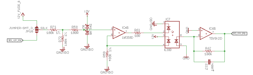
To measure signals that are inherently tied to battery voltage there are 2 linearized opto-isolated inputs. The following parameters can be configured:
| Parameter | Description |
|---|---|
| name | Sensor name. "voltmeter" is the only one currently used |
| opto_r1 | Isolated side (R59 in schematic below) |
| opto_r2 | Opto-isolator gain resistor R2 (R62 in schematic below) |
| input_r1 | High side resistor of voltage divider for input into opto-isolator. (R71 in schematic below) |
| input_r2 | Low side resistor of voltage divivider for input into opto-isolator. (R72 in schematic below) |
| k3 | Opto-isolator K3 gain (defined by linearized opto-isolator used and will have to be measured) |
| offset | Offset to voltage calculation, the linearized opto-isolator usually has an offset that will need to be accounted for. |
| x | Linearized opto-isolator input voltage calibration measurements. This is the high voltage side. The more measurement points the better. |
| y | Output voltage calibration measurements. This is the low voltage side. Ideally if there was zero offset and a K3 gain of 1.0 these should be x / 10. This is unlikely to be the case given the binning of the IL300 and LOC11x series. |
- In the config.ini file, set opto_r1, opto_r2, input_r1, input_r2, and k3 to 1.0.
- In the config.ini file, set offset to 0.0.
- Reboot the dash.
- The output for the voltmeters will now be the real input to the ADC. Usually between 1V-2V for inputs from 8V to 16V.
- With the car on but not running, measure the voltage at fuse 8. This will be your first x value. Take the output of the voltmeter (somewhere between 1V-2V). This will be your first y value.
- Start the car and repeat the above step. These will be your second x and y values.
- Enter the values determined above in the config.ini file.
- Reset the opto_r1, opto_r2, input_r1, input_r2 to their previous values. You can leave offset and k3 alone. The software will use your calibration values to calculate the k3 gain and offset.
- Reboot the dash and verify that the voltages with the car on and running match what you had measured before.
Note on K3 gain calibration values: Ideally, you would want way more than just 2 points to calibrate with. If you have access to an adjustable power supply it is recommended to take 5+ measurements from 8V-16V.
The default configuration is as follows:
[12v_analog]
size=2
[12v_analog/1]
name="voltmeter"
opto_r1=490000.0
opto_r2=100000.0
input_r1=100000.0
input_r2=100000.0
k3=1.1536
offset=.087985
x=8.25, 9.05, 9.87, 10.67, 11.52, 12.37, 13.30, 14.15, 14.96, 15.78, 16.78
y=1.05, 1.15, 1.25, 1.35, 1.45, 1.55, 1.65, 1.76, 1.85, 1.95, 2.05
[12v_analog/2]
name="rheostat"
opto_r1=490000.0
opto_r2=100000.0
input_r1=100000.0
input_r2=100000.0
k3=1.1536
offset=.087985
x=8.25, 9.05, 9.87, 10.67, 11.52, 12.37, 13.30, 14.15, 14.96, 15.78, 16.78
y=1.05, 1.15, 1.25, 1.35, 1.45, 1.55, 1.65, 1.76, 1.85, 1.95, 2.05
RPM is estimated by measuring the time difference between pulses from the negative terminal of the ignition coil. The following parameters can be configured:
| Parameter | Description |
|---|---|
| pulse_per_rot | Number of tach pulses per rotation (number of cylinders / 2) |
| max_rpm | Maximum RPM to resolve. This should be as low as possible. |
| avg_num_samples | Number of samples to average over to estimate RPM |
The default configuration is as follows:
[tach_input]
pulse_per_rot=2
max_rpm=9000
avg_num_samples=4
Designed to used the stock 240 diff cover VSS. The vehicle speed can be estimated using the number of pulses coming from the VSS sensor for every rotation of the rear diff. The following parameters can be configured:
| Parameter | Description |
|---|---|
| pulse_per_rot | Number of VSS pulses per rotation (12 for non-ABS and 48 for ABS equipped 240s) |
| tire_diameter | Tire diameter (can be used to calculate pulses per unit distance) |
| diameter_units | Tire diameter units: "inch", "centimeter", "millimeter", "foot", etc |
| pulse_per_unit_distance | Number of pulses per units distance. |
| distance_units | Distance units for pulses per unit distance: "mile", "kilometer |
| max_speed | max speed (distance_units / hour). Keep as low as possible to avoid picking up noise as VSS pulses |
The default configuration is as follows:
[vss_input]
pulse_per_rot=12
tire_diameter=24.9
diameter_units="inch"
pulse_per_unit_distance=9720
distance_units="mile"
max_speed="185"
The stock 240 dimming circuit (Pin 10 on the circular Volvo connector 31) can be used to dim the backlight of the LCD by injecting a PWM signal into the LCD control board. Back light control with the dimmer knob only works when the headlights or running lights are engaged. Otherwise, the dimmer rheostat does not receive voltage.
The following parameters can be configured:
| Parameter | Description |
|---|---|
| max_duty_cycle | Maximimum duty cycle of backlight PWM signal (min_duty_cycle-1.0) |
| min_duty_cycle | Minimum duty cycle of backlight PWM signal (0-max_duty_cycle) |
| lights_off_duty_cycle | Default duty cycle to use when the headlights or running lights are off |
| lights_on_duty_cycle | Default duty cycle to use when headlights or running lights are on |
| min_dimmer_ratio | rheostat voltage as a percentage of battery voltage at dimmest setting |
| max_dimmer_ratio | rheostat voltage as a percentage of battery voltage at brightest setting |
| use_dimmer | flag to use/don't use dimmer |
| active_low | PWM signal active low flag |
The default configuration is as follows:
[backlight]
max_duty_cycle=1.0
min_duty_cycle=0.05
lights_off_duty_cycle=1.0
lights_on_duty_cycle=0.5
min_dimmer_ratio=0.82
max_dimmer_ratio=0.93
use_dimmer=0
active_low=1
Rev C hardware added components to interface with CAN outputs from an aftermarket ECU. The MCP2515 driver and can0 network interface are loaded when the dash boots and the Dash Qt app attempts to load CAN frame configuration from the config_can.ini file. To date this has only been tested with a Microsquirt on a bench with simulated inputs. If the CAN interface is enabled in the CAN config file, the dash will preferentially use the frame data for a specific gauge over a hardware sensor.
Under the [start] heading in the CAN config file, there is a single option:
| Parameter | Description |
|---|---|
| use | true/false to enable/disable the use of incoming CAN data |
Under the [can_frame] heading will come the CAN frame data settings. This is setup based upon information found here.
| Parameter | Description |
|---|---|
| frame_id | CAN Frame ID where data is present |
| offset | Offset within frame where the data is present |
| data_size | Data size in bytes |
| signed | true if data is signed |
| name | Name of data (map, rpm, tps, etc) -- default values come from the simplified CAN broadcast data from Megasquirt |
| units | Units of data |
| multiply | Factor to multiply raw value by |
| divide | Factor to divide raw value by |
| add | Value to add to raw value |
| gauge | Gauge to route data to. |
Order of operations is (raw_data * multiply_factor / divide_factor) + add_value. Is this right? No idea.
Example configuration:
[start]
use=false
[can_frame]
size=7
[can_frame/1]
frame_id=1512
offset=0
data_size=2
signed=true
name="map"
units="kPa"
multiply=1
divide=10
add=0
gauge="boost"
[can_frame/2]
frame_id=1512
offset=2
data_size=2
signed=false
name="rpm"
units="rpm"
multiply=1
divide=1
add=0
gauge="tacho"
[can_frame/3]
frame_id=1512
offset=4
data_size=2
signed=true
name="clt"
units="F"
multiply=1
divide=10
add=0
gauge="coolant_temp"
[can_frame/4]
frame_id=1512
offset=6
data_size=2
signed=true
name="tps"
units="%"
multiply=1
divide=10
add=0
gauge="none"
[can_frame/5]
frame_id=1513
offset=4
data_size=2
signed=true
name="mat"
units="F"
multiply=1
divide=10
add=0
gauge="none"
[can_frame/6]
frame_id=1515
offset=0
data_size=2
signed=true
name="batt"
units="V"
multiply=1
divide=10
add=0
gauge="voltmeter"
[can_frame/7]
frame_id=1516
offset=0
data_size=2
signed=true
name="vss1"
units="msec^-1"
multiply=1
divide=10
add=0
gauge="none"