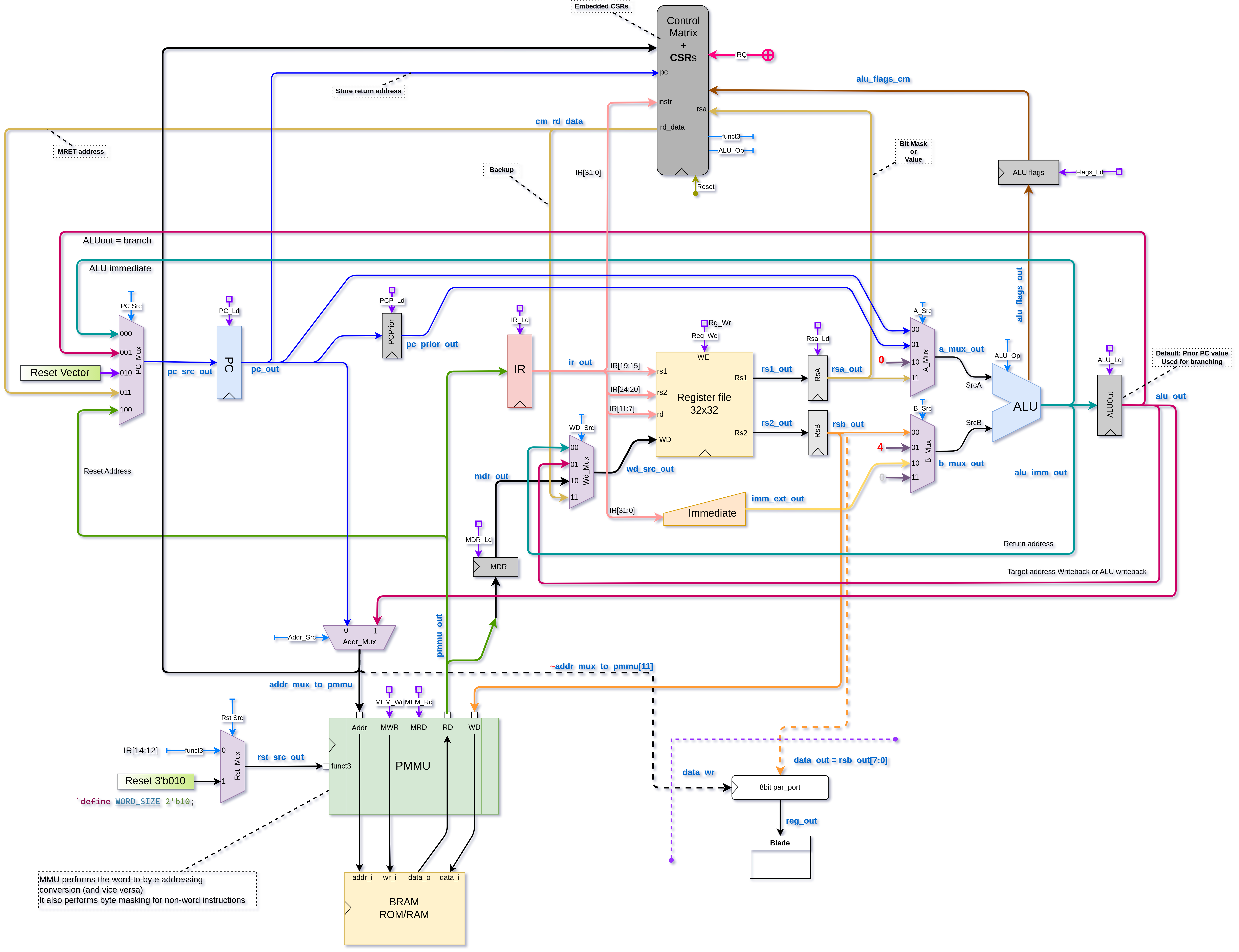
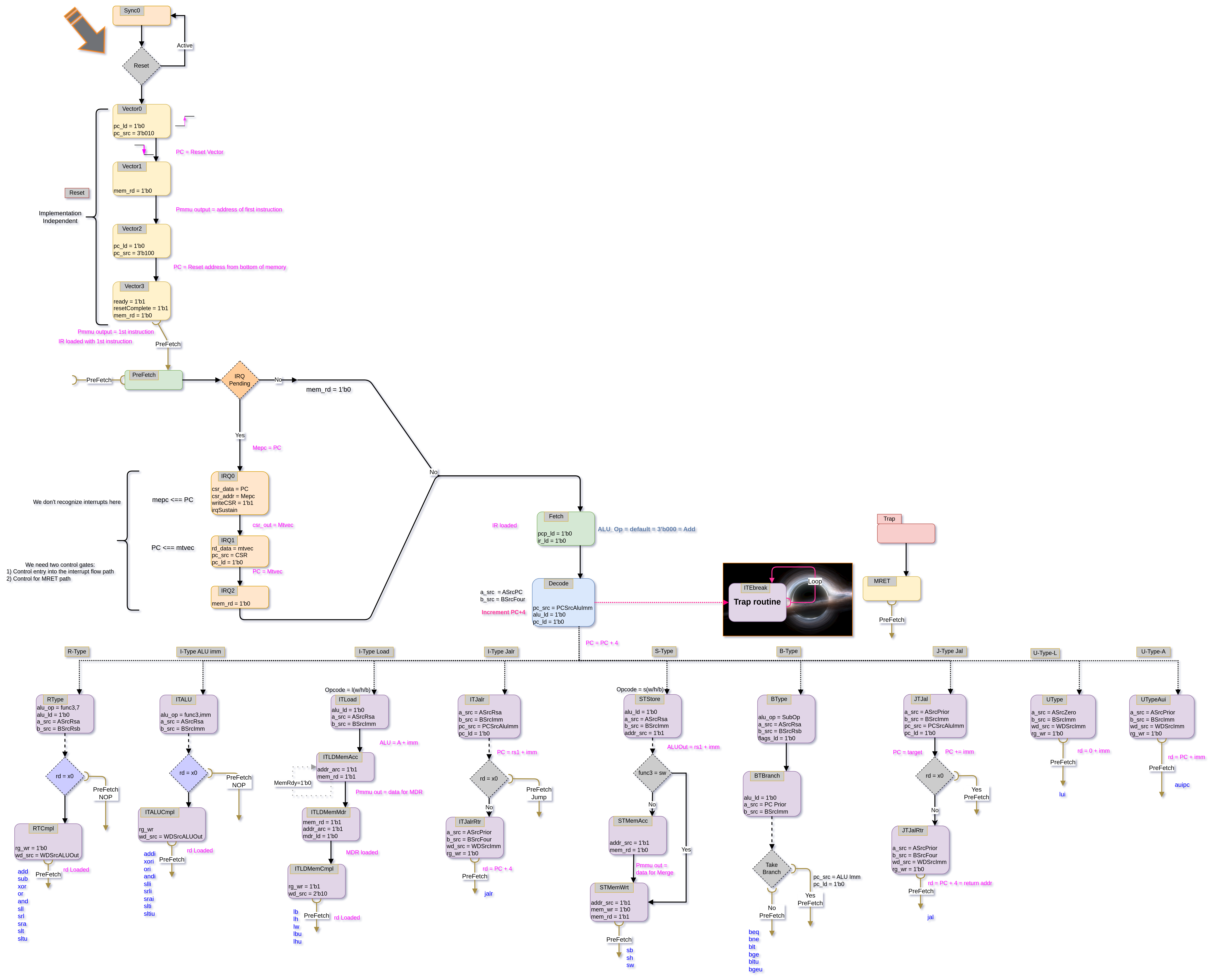
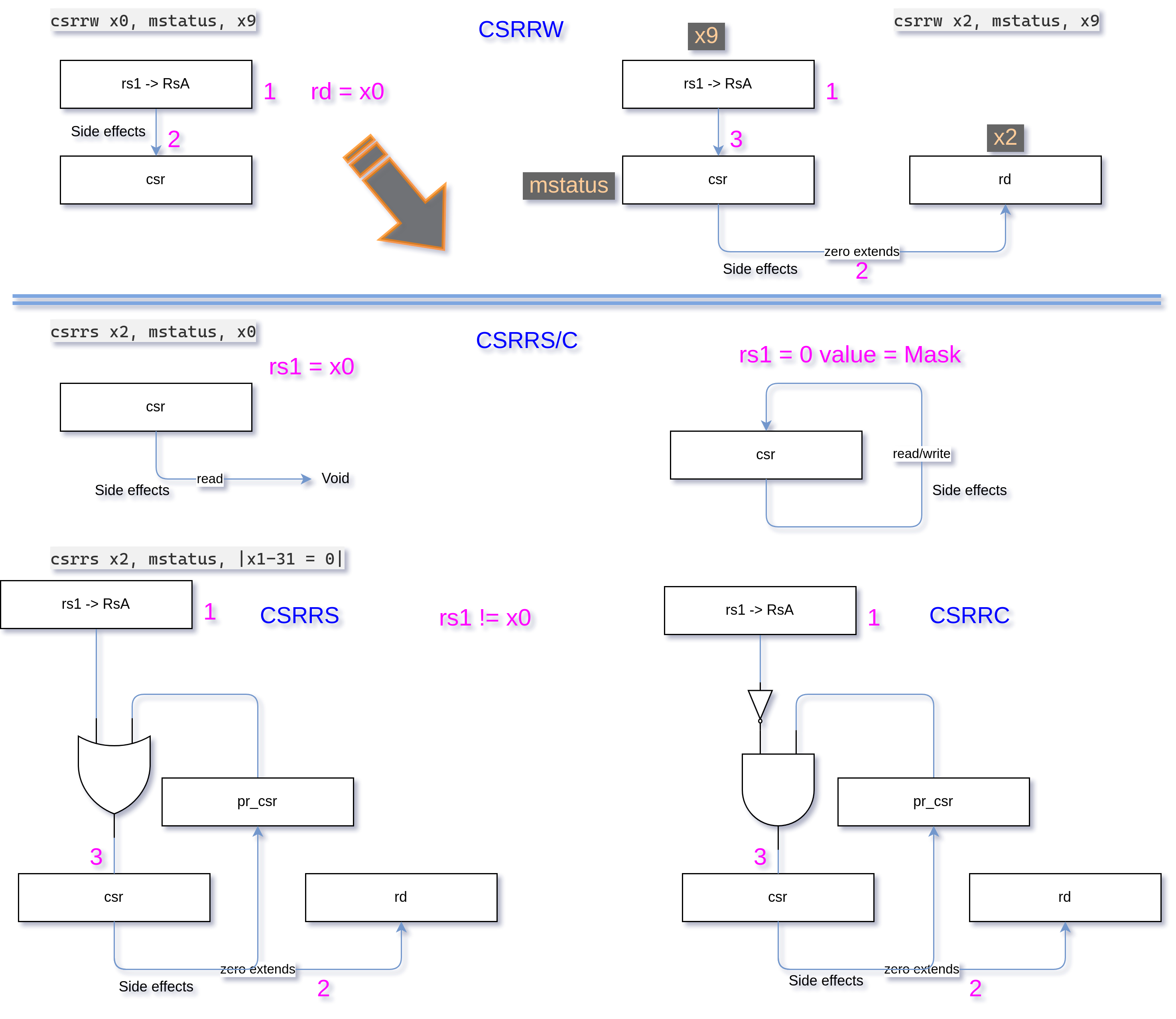
Ranger Risc softcore SystemVerilog RISC-V Multicycle variant.
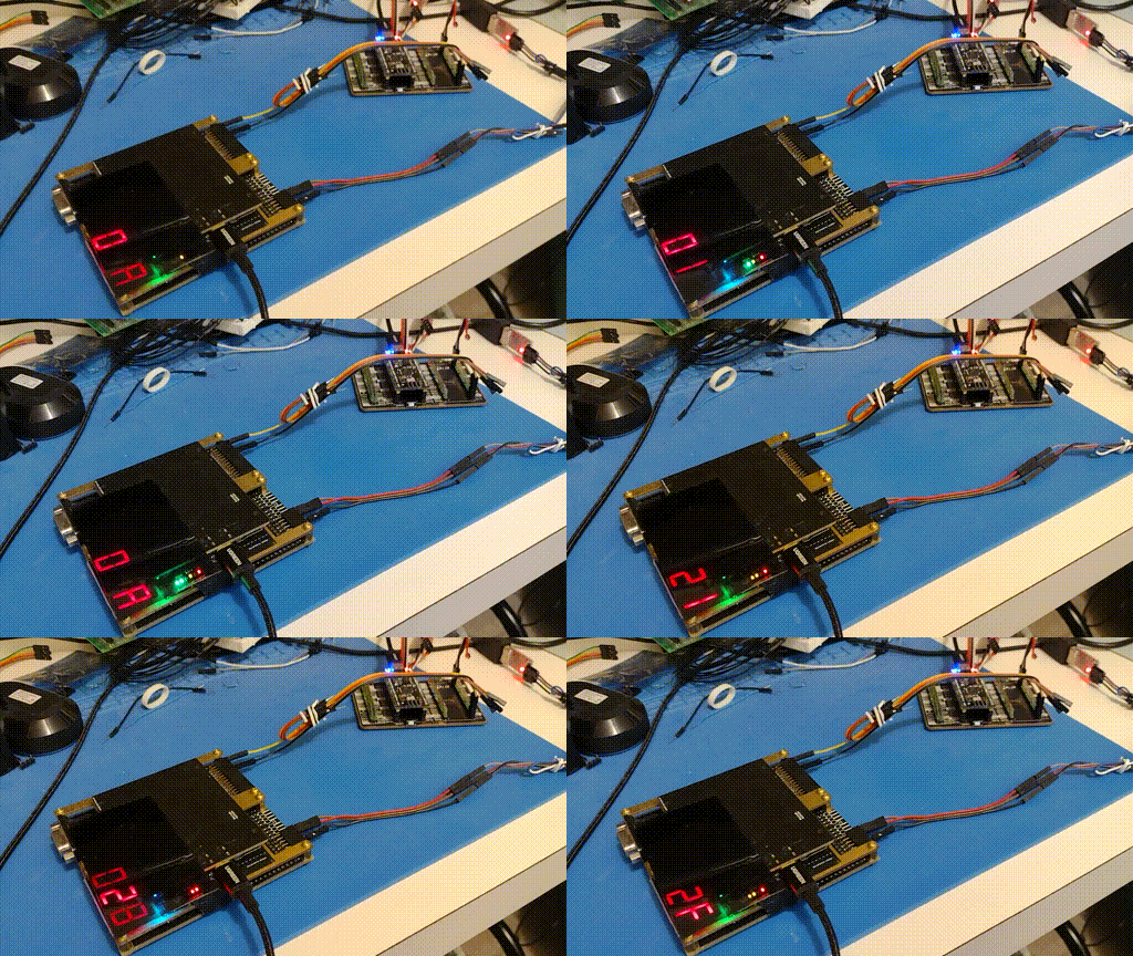
The video shows BlackiceEdge hosting RangerRisc. The softcore RISC-V assembly program is counting and displaying on the 7seg. The blade shows the interrupt count and the Blue LED flicking shows the interrupt signal.
On the upper PMOD is the Interrupt signal coming from the Pico RP2040. On the lower PMOD is the UART channel for talking to a UART client (written in Go.)
The repo contains two variations: a debug version with controls signals routed out via UART and a release version that is trimmed down.
NOTE This repo does NOT contain the Simulation code base. For simulation please see the RISC-V-RV32I-MultiCycle repo under the simulation folder.
- assemblies Contains all assembly code examples. Note most of them are more compatible with the 48Hz clock.
- debug Contains the debug variant which contains a bunch of exposed signals for displaying.
- definitions has common definitions
- modules has all the common modules
- rams generally contains only a single code.ram file
- release This the stripped down variant and can run about 1.23MHz faster
- tools contains two Go programs: an Assembler and UART client
- gen-instr (i.e. the Assembler)
- The assembly.json is configured for release variant.
- go-uart (the UART client for talking with fpga)
- gen-instr (i.e. the Assembler)
Sometimes you need to re-upload the bitstream image for it to boot correctly.
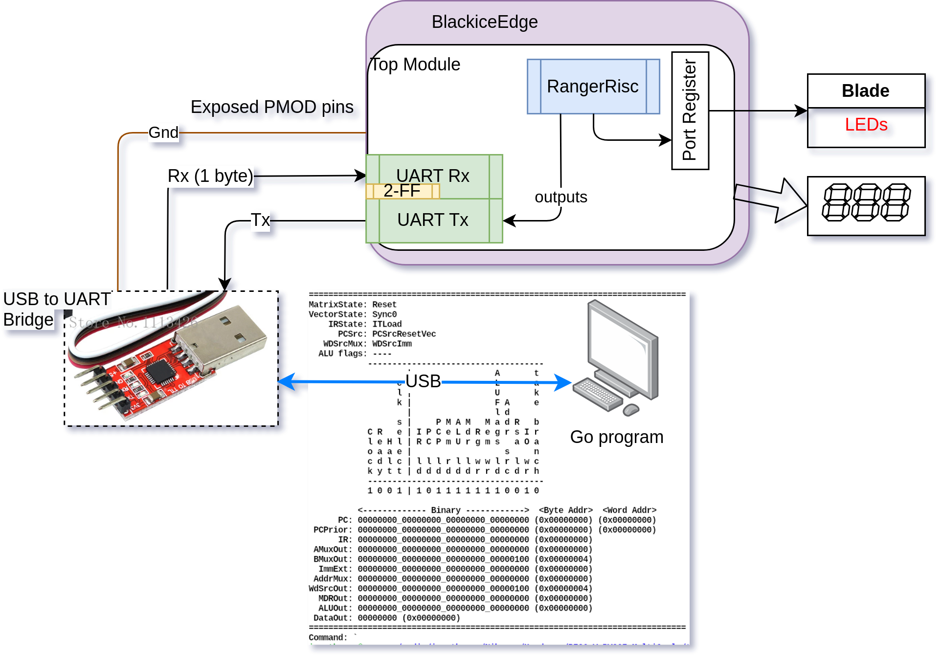
The Top module contains a huge amount of code to support transmitting data from the fpga to a UART client. This includes UART, blade port and 7seg port.
It consumes about 3500 LUTs!:
Info: Max frequency for clock 'clk$SB_IO_IN_$glb_clk': 47.49 MHz (PASS at 18.00 MHz)
Info: Max frequency for clock    'cpu_clock_$glb_clk': 19.19 MHz (PASS at 18.00 MHz)

Info: Device utilisation:
Info: 	         ICESTORM_LC:  3501/ 7680    45%
Info: 	        ICESTORM_RAM:    12/   32    37%
Info: 	               SB_IO:    23/  256     8%
Info: 	               SB_GB:     7/    8    87%
Info: 	        ICESTORM_PLL:     1/    2    50%
Info: 	         SB_WARMBOOT:     0/    1     0%
This version is trimmed down. It doesn't have UART or exposed core signals. This saves 905 LUTs.
Also, a slightly higher clock can be used resulting in a boost of: 1.23MHz. Note however, the makefile is still configured for 18MHz.
This version is also hardcoded to 18MHz, hence, make sure your assembly code compensates for the higher clock. For example, any counting code should have some form of delay added.
Info: Max frequency for clock 'clk$SB_IO_IN_$glb_clk': 197.75 MHz (PASS at 18.00 MHz)
Info: Max frequency for clock    'clk_18MHz_$glb_clk': 20.42 MHz (PASS at 18.00 MHz)

Info: Device utilisation:
Info: 	         ICESTORM_LC:  2596/ 7680    33%
Info: 	        ICESTORM_RAM:    12/   32    37%
Info: 	               SB_IO:    21/  256     8%
Info: 	               SB_GB:     7/    8    87%
Info: 	        ICESTORM_PLL:     1/    2    50%
Info: 	         SB_WARMBOOT:     0/    1     0%
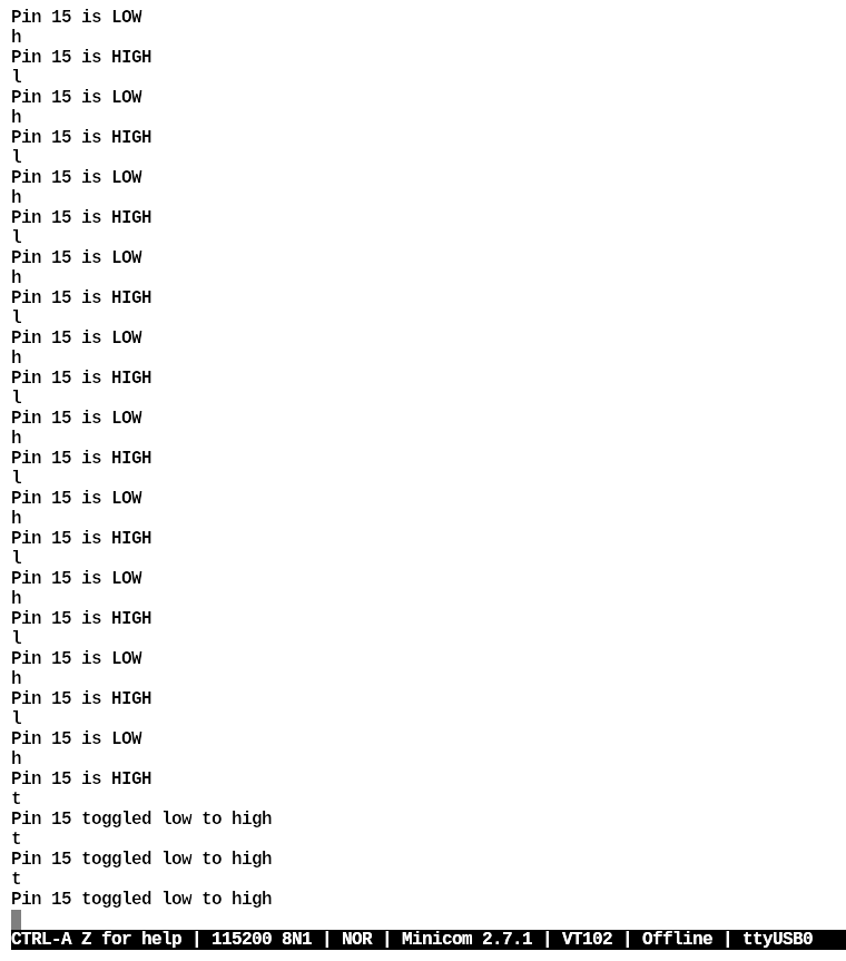
This terminal is for connecting to the Pico using:
minicom -b 115200 -o -D /dev/ttyUSB0
Once the Pico has been programmed with the control software via build/io_uart. You can use "h" or "l" for manual high/low control of the active pin. Or you can use "t" to toggle the active pin.
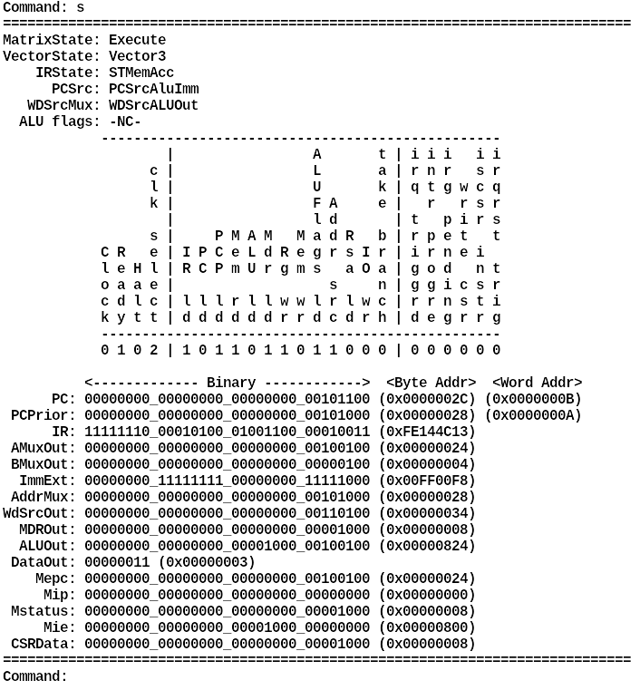
This terminal is for talking to the fpga's UART module. The two most commonly used commands are "s" and "c" or "k" (48Hz) or "l" (18MHz).
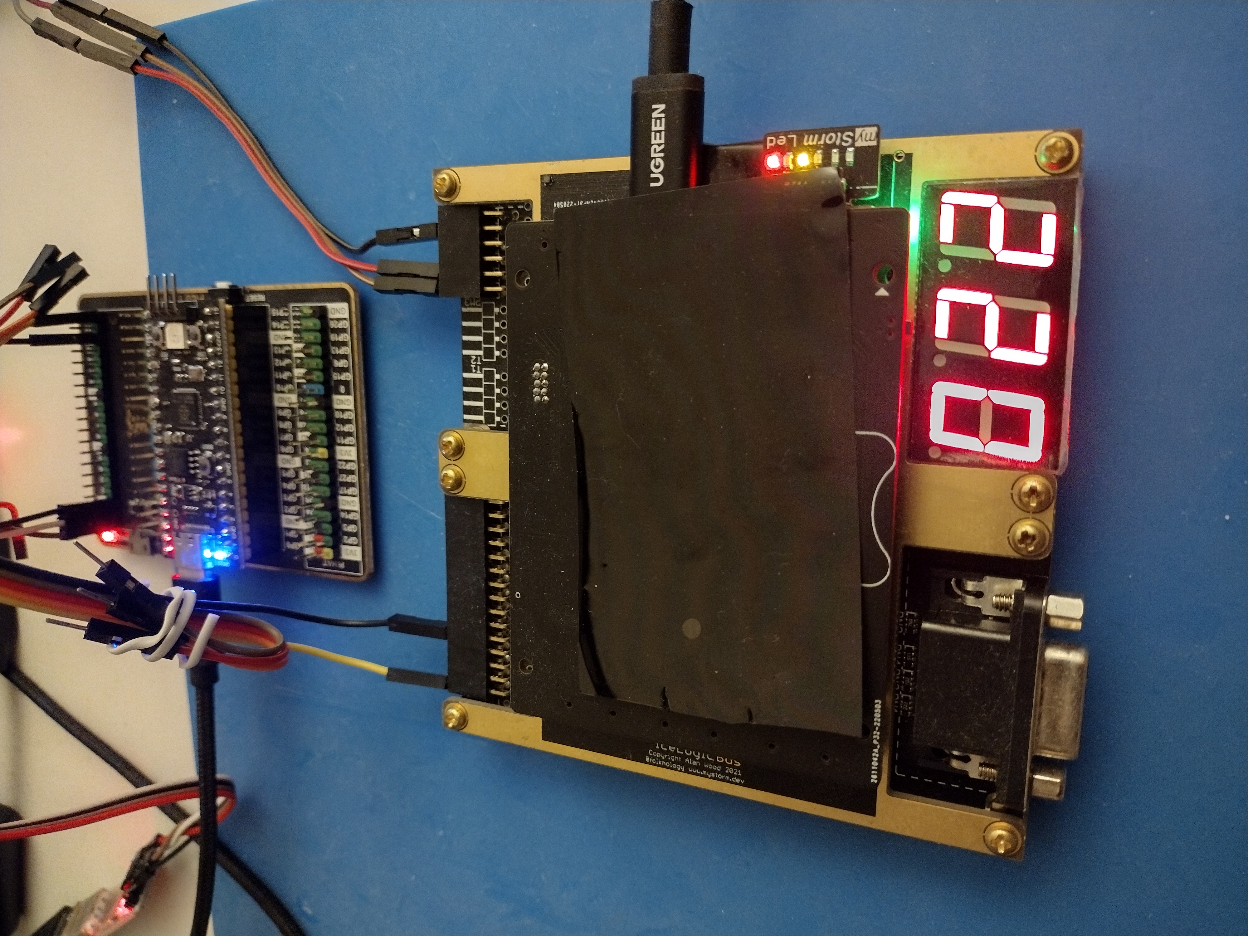
Up top is the Pico for generating an interrupt on Pin 15 which is routed to the left pmod.
On the right pmod is the UART connections for talking between the fpga and the Go control program.
Super high level usage guide:
- Program the Pico and connect the Pico's UART and
- Connect Pin 15 to the left fpga pmod
- Connect second USB-UART to fpga via pmods (on the right).
- Connect fpga to USB. The BlackiceEdge shows up as ttyACM0
- cd into RangerRisc-RISC-V<...> and run
make - go to the go-uart bin directory and run
go run . - use the commands to direct the fpga top module
- use minicom to direct the pico to toggle a pin to generate interrupts.
Nihongo/Hardware/Risc-v/TopReference/risc-v-asm-manual.pdf
The instructions themselves need to have the offset specified in byte-address form, however, the memory addresses can be defined as byte-address using "$" or word-address using "@".
If an instruction references an address that is defined in word-address form then it is converted to byte-address form even if it refers to a word-address. This is per the RISC-V ISA specs.
You need to do several things in order for the cpu to run code on the FPGA. Open 3 terminals: one for the assembler, another for HDL toolchain and another for the go UART client.
- Create or modify your
<file>.asmprogram and make sure you update the assembler's assembly.json file. The assemlby files are typically stored in the assemblies under the application root folder. - Open a terminal and cd to <path to>/tools/gen-instr/assembler folder
- Run the assembler
go run . <file>.asmto produce the code.ram file that is embedded into the fpga bit stream via the$readmemhcommand. - Open another terminal and cd to <path to>/Synthesis/ranger_risc folder and run
make. - Open another terminal and cd to <path to>/tools/go-uart and run
go run .
update the inputPath and inputFile keys to the .asm file you are targeting. Also, update the RamDir to direct the assembled ram code to a destination.
Then run go run . or go run . <file>.asm
Main: @
    lw x1, 0x28(x0)     // 0x28 BA = 0x0A WA
    ebreak              // Stop

Data: @00A
    d: DEADBEEF         // data to load

RVector: @0C0           // 0x300 BA = 0xC0 WA
    @: Main             // Reset vector
The RVector's value is what is defined in the makefile entry:
RESET_BOOT_VECTOR = "32'h00000300" # @0C0
After running the assembler you get a helpful yet extra code.out for cross reference:
@00000000 02802083 lw x1, 0x28(x0)     // 0x28 BA = 0x0A WA
@00000001 00100073 ebreak              // Stop
@0000000A DEADBEEF d: DEADBEEF         // data to load
@000000C0 00000000 @: Main             // Reset vector
There are two ways we can setup a macro for injecting dynamic definitions in verilog code. I prefer #1.
- Create a file, for example, definitions.sv with a
`define ROM_PATH "../rams/" - Or, add a variable and macro definition to a makefile:
CODE_PATH = "\"../rams/\""
...
	-DRAMROM_PATH=${CODE_PATH} \
Then define a localparam as: localparam RomPath = `RAMROM_PATH; some place you need it, for example, memory.sv.
Here is an example:
CODE_PATH = "\"../rams/\""

.PHONY: all

all: build route upload

compile: build route

build: ${MODULES_FILES} ${PINS_CONSTRAINTS}
	@echo "##### Building..."
	${ICESTORM_TOOLCHAIN}/bin/yosys -p ${YOSYS_COMMAND} \
	-l ${BUILD_BIN}/yo.log \
	-q \
	-defer \
	-DRESET_VECTOR=${RESET_BOOT_VECTOR} \
	-DRAMROM_PATH=${CODE_PATH} \
	-DUSE_ROM \
	-DDEBUG_MODE \
${MODULES_FILES}Folknology has an excellent page for describing how to use the simple mode capability of the lattice iCE40 fpga: https://github.com/mystorm-org/BlackIce-II/wiki/PLLs
We need an ~18MHz clock because nextpnr has trouble routing anything faster. So we use icepll to generate our control parameters:
icepll -i 25 - o 18
This will generate:
F_PLLIN:    25.000 MHz (given)
F_PLLOUT:   18.000 MHz (requested)
F_PLLOUT:   17.969 MHz (achieved)

FEEDBACK: SIMPLE
F_PFD:   25.000 MHz
F_VCO:  575.000 MHz

DIVR:  0 (4'b0000)
DIVF: 22 (7'b0010110)
DIVQ:  5 (3'b101)

FILTER_RANGE: 2 (3'b010)
However, icepll can also generate example code too:
icepll -i 25 -o 18 -m -f pll.v
