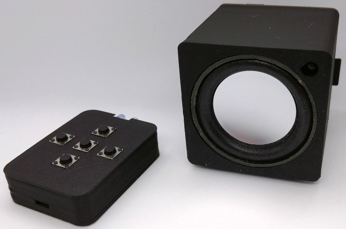
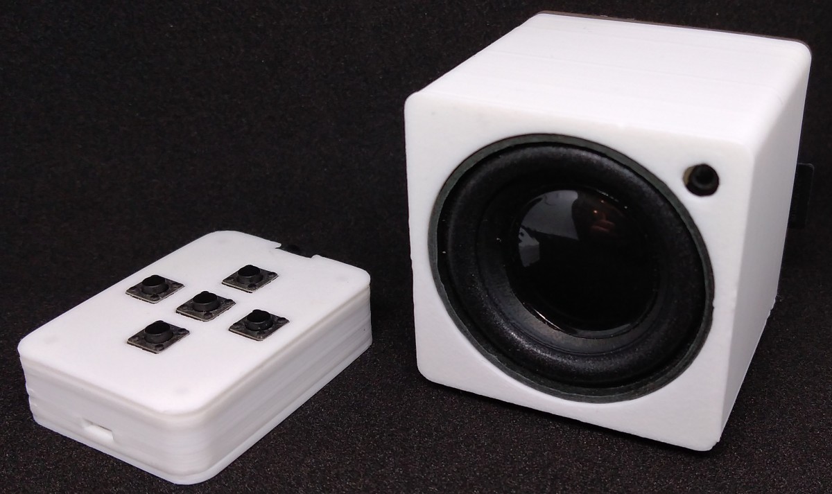
TinyPlayer is an IR remote controlled and LiPo battery powered MP3 player based on ATtiny13A and DFPlayerMini module. The DFPlayer module is controlled via a simple cycle-precise software implementation of the UART protocol (8N1, 9600 BAUD) in half-duplex mode. The volume last set as well as the track number last played are saved in the EEPROM and automatically loaded the next time it is started. TinyPlayer has a built-in battery charging circuit, which is supplied with power via a USB-C connector. You can directly connect a 3.7V LiPo battery and a 3W/4Ohm speaker to the board.
- Project Video (Youtube): https://youtu.be/XRpFHvouraQ
- Design Files (EasyEDA): https://easyeda.com/wagiminator/attiny13-tinyplayer
The DFPLayer Mini module is a serial MP3 module that offers the perfect built-in MP3 hardware decoding. It supports TF cards with FAT16 and FAT32 file systems. Music playback as well as other functions can be controlled by simple serial commands without cumbersome software implementation. The main features of the module are easy to use, stable and reliable functions.
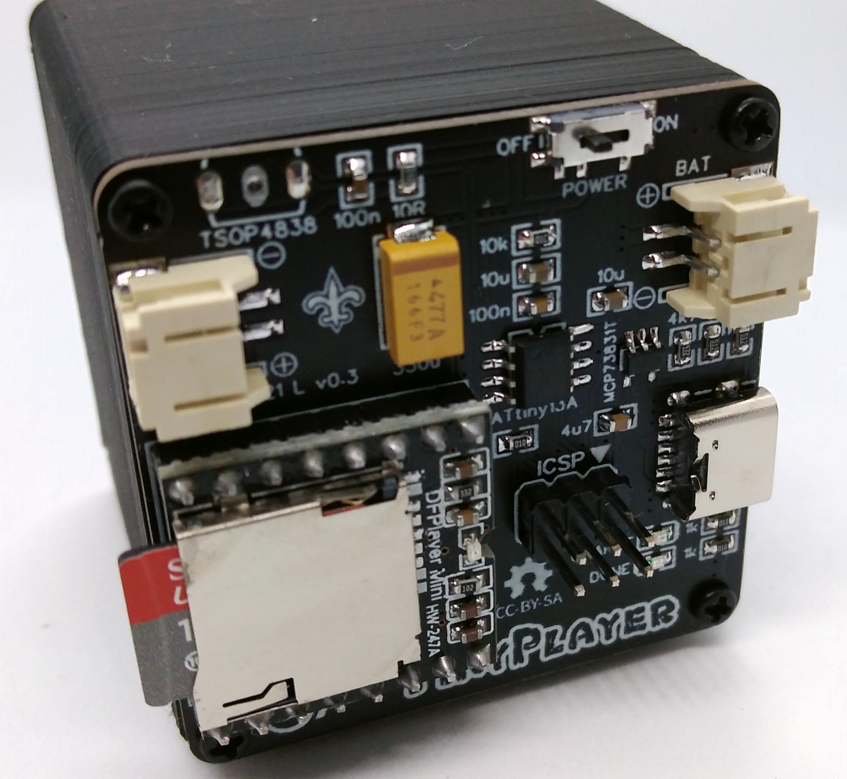
For battery charging the MCP73831 is used. The MCP73831 is a highly advanced linear charge management controller for use in space-limited, cost-sensitive applications. It employs a constant-current/constant-voltage charge algorithm with selectable preconditioning and charge termination. The constant current value is set with one external resistor (R6). Charging is done via the built-in USB-C connector.
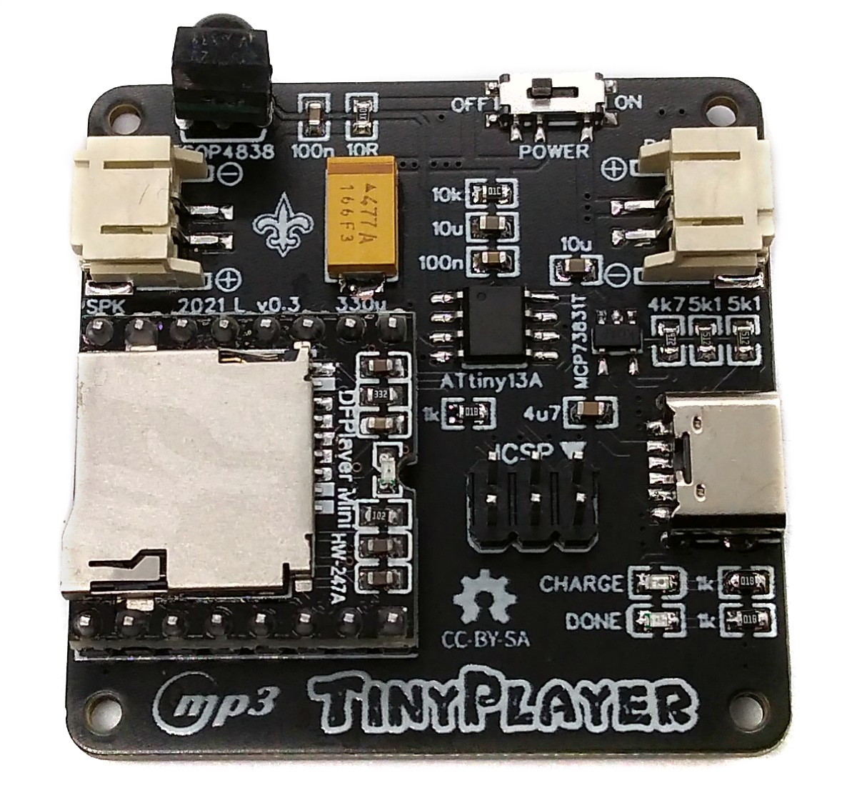
The device is completely controlled via an IR remote control. A TSOP4838 is used to receive the IR signals. An ATtiny13A microcontroller brings it all together.
UART stands for Universal Asynchronous Receiver Transmitter. It is a serial interface, whereby the data transfer takes place asynchronously (i.e. without its own clock signal). A UART interface has two connections: TxD and RxD (often also referred to as Tx and Rx) and a common ground connection. TxD stands for Transmit Data. From here, data is sent to the communication partner. So the TxD pin acts as an output pin. RxD stands for Receive Data. Data is received from the communication partner from here. So the RxD pin acts as an input pin. The connections of the communication partners are cross-linked, i.e. the TxD output of the first system is connected to the RxD input of the second system and vice versa. Only two partners can be connected to each other using UART.
Since UART data transmission is asynchronous data transfer, there is no clock signal with which the transmitter and receiver can synchronize. Since the UART protocol is a binary baseband signal, the bit rate is the same as the baud rate (symbol rate). The baud rate (transmission speed) must be set identically for both communication partners.
The data transmission via UART takes place with a fixed data frame (UART frame). This must be known to both communication partners. A UART frame consists of:
- a start bit
- 5-9 data bits
- an optional parity bit
- one or two stop bits
The start bit in the UART protocol is required so that the communication partners can synchronize. In the idle state, the UART bus is at logic 1 (HIGH). The start bit is logic 0 (LOW) and signals the start of a UART frame. The start bit is followed by 5 to 9 data bits. These are sent in little-endian format, i.e. the LSB (least significant bit) first. For a "0"-bit the UART bus line ist set to LOW, for a "1"-bit it is set to HIGH. The parity bit is optional. It is used to detect errors. The UART frame is terminated by one or two stop bits. Sometimes an extended stop bit (1.5 stop bits) is also used. Stop bits have the status logical 1 (HIGH).
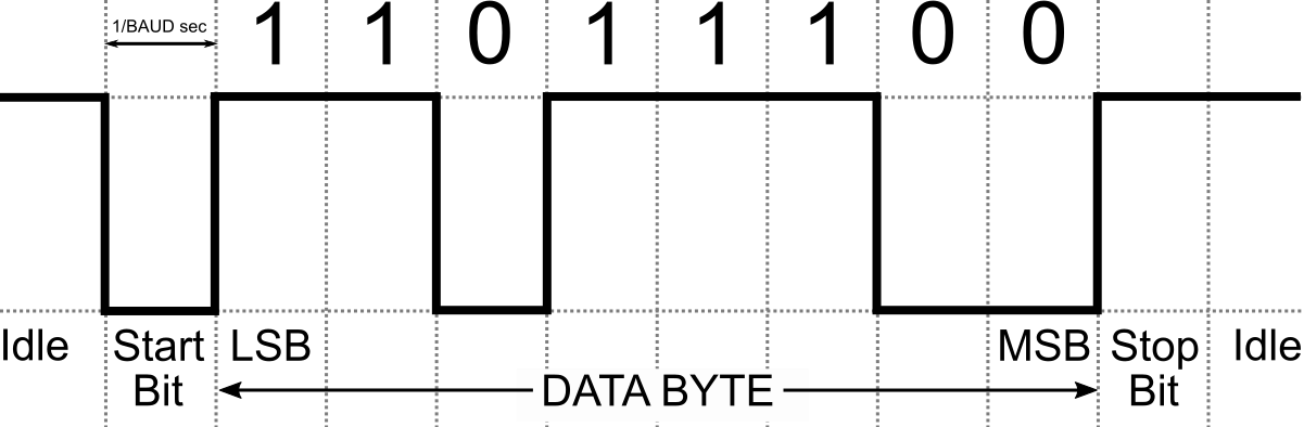
There is an abbreviated notation for the format of UART frames. 8N1 means: 8 data bits, no parity bit, 1 stop bit. The 8N1 format is often used when transferring data from microcontroller to PC or other devices and is also used here.
The implementation is for half-duplex, so it is not possible to send and receive at the same time. It is cycle-accurate due to the use of the delay_cycles function instead of delay_us. The number of MCU clock cycles per UART bit is simply calculated by dividing the MCU clock rate by the UART BAUD rate. By analyzing the compiled and reassembled code, the timing can be determined with an accuracy of a single MCU clock cycle. So here's the initialization part of the UART implementation:
// UART macros
#define UART_TX_setHigh()   PORTB |=  (1<<TX_PIN)
#define UART_TX_setLow()    PORTB &= ~(1<<TX_PIN)
#define UART_RX_isHigh()    PINB  &   (1<<RX_PIN)
#define UART_RX_isLow()     ~PINB &   (1<<RX_PIN)

// UART timings
#define UART_BAUD           9600UL              // UART BAUD rate
#define UART_BC             F_CPU / UART_BAUD   // MCU cycles per UART bit

// UART init
void UART_init(void) {
  PORTB |= (1<<TX_PIN);                         // TX HIGH
  DDRB  |= (1<<TX_PIN);                         // TX as output
  GIMSK |= (1<<PCIE);                           // enable pin change interrupts
  PCMSK |= (1<<RX_PIN);                         // enable PC interrupt on RX pin
}
The transmission part of the implementation is pretty simple bit-banging (it's just a matter of precise timing):
// UART transmit byte
void UART_write(uint8_t byte) {
  cli();                                        // disable interrupts
  UART_TX_setLow();                             // transmit start bit
  __builtin_avr_delay_cycles(UART_BC - 6);      // wait till end of start bit
  for (uint8_t i=8; i; i--, byte>>=1) {         // 8 bits, LSB first
    if (byte & (0x01))  { asm("nop"); UART_TX_setHigh(); }      // "1" - bit
    else                { UART_TX_setLow(); asm("rjmp .+0"); }  // "0" - bit
    __builtin_avr_delay_cycles(UART_BC - 11);   // wait till end of bit
  }
  __builtin_avr_delay_cycles(4);                // cycle overhead
  UART_TX_setHigh();                            // transmit stop bit
  __builtin_avr_delay_cycles(UART_BC - 8);      // wait till end of stop bit
  sei();                                        // enable interrupts
}
The receiver part of the implementation is interrupt-triggered and uses an 11-byte receive buffer. The state of the RX line is determined at the middle of each UART bit cycle.
// UART variables
volatile uint8_t UART_RX_BUF[11];               // UART receive buffer
volatile uint8_t UART_RX_PTR = 0;               // UART receive buffer pointer

// UART receive byte (pin change interrupt service routine)
ISR(PCINT0_vect) {
  if (UART_RX_isLow()) {                        // interrupt caused by start bit ?
    uint8_t byte;                               // byte to be received
    __builtin_avr_delay_cycles((UART_BC/2)-27); // wait for first bit
    for (uint8_t i=8; i; i--) {                 // receive 8 Bits
      byte >>= 1;                               // LSB first
      __builtin_avr_delay_cycles(UART_BC - 10); // wait for next bit
      if (UART_RX_isHigh()) byte |= 0x80;       // read bit
    }
    UART_RX_BUF[UART_RX_PTR++] = byte;          // write byte to buffer
    if (UART_RX_PTR > 10) UART_RX_PTR = 10;     // limit pointer (not a ring buffer)
  }
}
Since the code was programmed quick and dirty, this is certainly not the most efficient method of software UART implementation, even if it works without problems and cuts a good figure in the logic analyzer. For a more sophisticated implementation, check out Ralph Doncaster's PicoUART.
The DFPlayer Mini module is controlled via UART at 9600 BAUD. There are various commands to be sent, which are described in the datasheet. Unfortunately, the datasheet is not only incomplete, but also partially incorrect. It is therefore worth taking a look at the common Arduino library implementations on the one hand, and evaluating the signals with a logic analyzer on the other.
A command string always consists of 10 bytes (or 8 bytes if the checksum is not used). These are in order:
| Byte | Value |
|---|---|
| Start Byte | always 0x7E |
| Version | seems to be always 0xFF |
| Length | total number of bytes excluding start/end byte and checksum; seems to be always 0x06 |
| Command | command byte (see below) |
| Feedback | 0x00: no feedback; 0x01: request feedback |
| Parameter H | data high byte |
| Parameter L | data low byte |
| Checksum H | checksum high byte; not include start/end byte; can be omitted |
| Checksum L | checksum low byte; not include start/end byte; can be omitted |
| End Byte | always 0xEF |
The different command bytes are defined in the TinyPlayer source code:
// DFPlayer control commands (it's almost complete; only a few of them are used)
#define DFP_CMD_NEXT      0x01                  // play next file
#define DFP_CMD_PREV      0x02                  // play previous file
#define DFP_CMD_TRACK     0x03                  // play track (fileNumber)
#define DFP_CMD_VOLUP     0x04                  // volume up
#define DFP_CMD_VOLDOWN   0x05                  // volume down
#define DFP_CMD_VOL       0x06                  // set volume (0..30)
#define DFP_CMD_EQ        0x07                  // set equalizer
#define DFP_CMD_MODE      0x08                  // 0:repeat; 1:folder; 2:single; 3:random
#define DDP_CMD_OUTPUT    0x09                  // set output device
#define DFP_CMD_STBY      0x0A                  // enter standby
#define DFP_CMD_NORM      0x0B                  // normal working
#define DFP_CMD_RESET     0x0C                  // reset module
#define DFP_CMD_PLAY      0x0D                  // play
#define DFP_CMD_PAUSE     0x0E                  // pause
#define DFP_CMD_FOLDER    0x0F                  // play folder (folderNumber, fileNumber)
#define DFP_CMD_SETTING   0x10                  // output setting (enable, gain)
#define DFP_CMD_REPEAT    0x11                  // loop all (0:stop; 1:start)
#define DFP_CMD_MP3FOLD   0x12                  // play mp3-folder (fileNumber)
#define DFP_CMD_ADVERT    0x13                  // play advertise (fileNumber)
#define DFP_CMD_STOPADV   0x15                  // stop advertise
#define DFP_CMD_STOP      0x16                  // stop
#define DFP_CMD_LOOPFOLD  0x17                  // loop folder (folderNumber)
#define DFP_CMD_RANDOM    0x18                  // random all
#define DFP_CMD_LOOP      0x19                  // loop (0:enable; 1:disable)
#define DFP_CMD_DAC       0x1A                  // DAC (0:enable; 1:disable)

// DFPlayer query commands
#define DFP_QRY_STATE     0x42                  // query current status
#define DFP_QRY_VOL       0x43                  // query current volume
#define DFP_QRY_EQ        0x44                  // query current equalizer setting
#define DFP_QRY_MODE      0x45                  // query current playback mode
#define DFP_QRY_TRACKS    0x48                  // query total number of files
#define DFP_QRY_TRACK     0x4C                  // query current file number
#define DFP_QRY_FTRACKS   0x4E                  // query total files in (folderNumber)
#define DFP_QRY_FOLDERS   0x4F                  // query total number of folders
A response from DFPlayer always consists of 10 bytes as described above. The included command byte describes the type of response:
| Command Byte | Meaning |
|---|---|
| 0x3D | last track finished |
| 0x3F | initialization finished (after powering up) |
| 0x40 | error, retransmit last command string |
| 0x41 | feedback if requested with last command string (feedback byte 0x01) |
| 0x42..0x4F | query return according to last command string; parameter bytes hold the query result |
If a feedback was requested with the last transfer of a query command string (command byte 0x42..0x4F, feedback byte 0x01), the DFPlayer first sends the 10-byte feedback string (with command byte 0x41) and then the 10-byte query return string (with command byte 0x42..0x4F).
The IR receiver implementation requires 228 bytes of flash including decoding and error detection. Only the NEC protocol is supported, but this is used by almost all cheap IR remote controls. Alternatively, you can build such a remote control yourself with TinyRemote.
The NEC implementation works without timers and interrupts. Since the start burst of a NEC telegram lasts a full 9 ms, it is sufficient to poll the IR pin every now and then. When a start frame has been detected, the signal is then measured and decoded according to the NEC protocol. The program was tested with the TSOP4838, but it should also work with other 38kHz IR receivers (note different pinout if necessary).
The output of the IR reciever is inverted (active LOW), a burst is indicated by a LOW signal, a pause by a HIGH signal. IR message starts with a 9ms leading burst followed by a 4.5ms pause. Afterwards 4 data bytes are transmitted, least significant bit first. A "0"-bit is a 562.5µs burst followed by a 562.5µs pause, a "1"-bit is a 562.5µs burst followed by a 1687.5µs pause. A final 562.5µs burst signifies the end of the transmission. According to the data sheet of the TSOP4838, the length of the output signal differs from the transmitted signal by up to 158µs, which the code must take into account. The four data bytes are in order:
- the 8-bit address for the receiving device,
- the 8-bit logical inverse of the address,
- the 8-bit key-dependend command and
- the 8-bit logical inverse of the command.
The Extended NEC protocol uses 16-bit addresses. Instead of sending an 8-bit address and its logically inverse, first the low byte and then the high byte of the address is transmitted.
For a more detailed explanation on the NEC protocol refer to TinyRemote. Don't forget to define the used IR codes in the sketch!
There are two versions of the firmware. With the "mp3_folder" version, all MP3 files are packed into one folder. You can then use the remote control to jump to any title in the folder. With the "numbered_folders" version the MP3 files are organized in several folders. The remote control can then be used to switch between the folders and to jump to the individual tracks within the selected folder.
Error-free serial communication with the DFPlayer module requires precise timing. Usually the internal oscillator of the ATtiny13 used for this is not sufficiently accurate and the serial communication may not work due to an imprecise oscillator. It is therefore recommended to calibrate it manually. There are numerous instructions on how to do this on the Internet. Alternatively, the TinyICOC or the TinyCalibrator can be used for this. Set the determined calibration value at the top of the code before compiling.
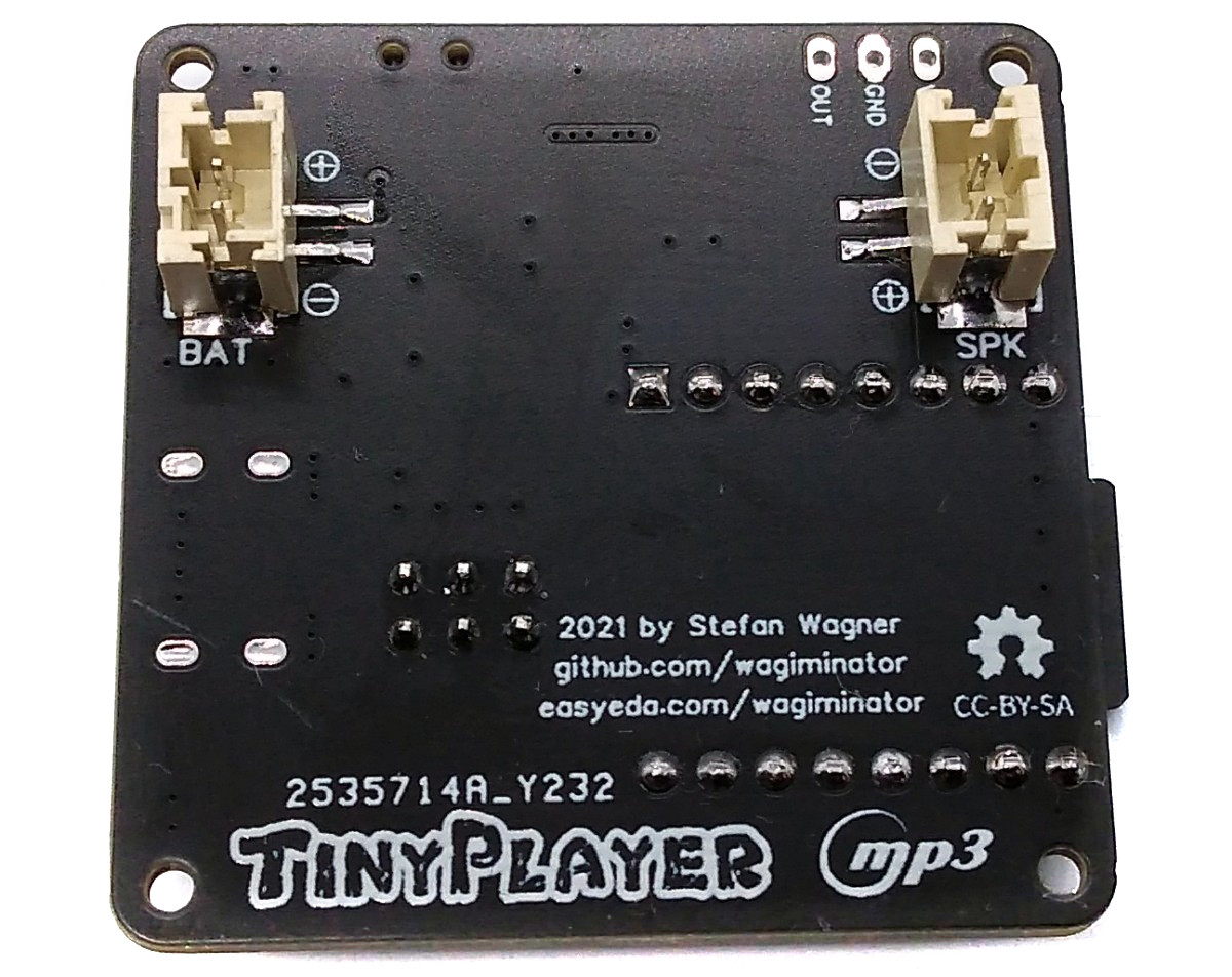
Solder all of the components onto the circuit board. Connect a 3.7 V Li-Po battery and a 3 W / 4 Ohm speaker to the corresponding pin headers.
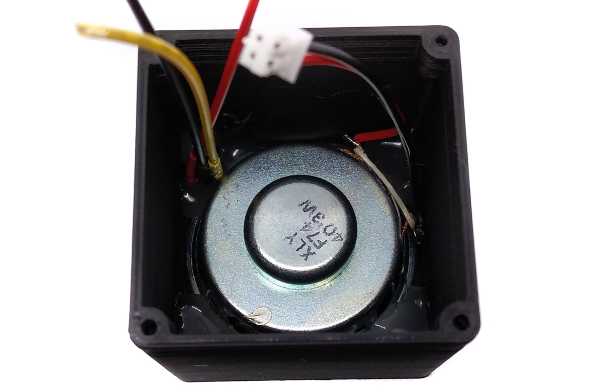
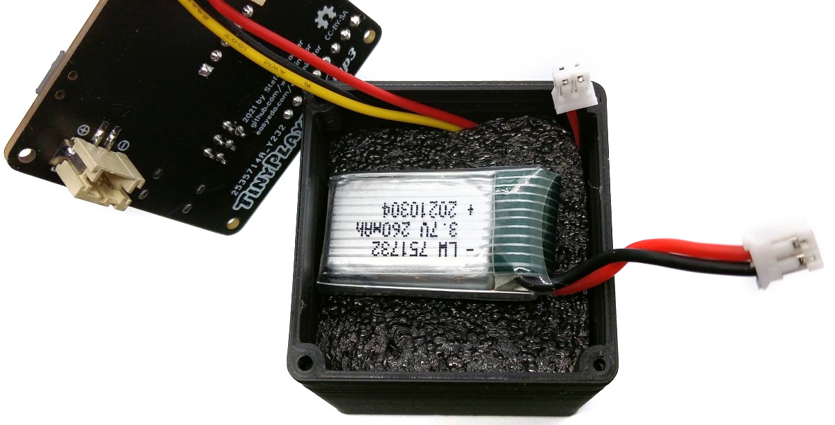
If you want to use the 3D-printed case, first install a 40mm speaker and the TSOP4838 with soldered wires in the housing and fix them with some hot glue. Place an approx. 1 cm thick piece of foam behind the speaker, which fits tightly against the outer walls of the housing. This improves the sound quality significantly and separates the battery from the speaker. Then place the battery. Make all connections to the TinyPlayer board. Screw on the board with 2 * 5 mm self-tapping screws. Glue four rubber feet to the underside of the player.
Open the TinyPlayer Sketch and adjust the IR codes so that they match your remote control. Remember that only the NEC protocol is supported.
// IR codes
// IR codes
#define IR_ADDR       0x1A    // IR device address
#define IR_VOL_P      0x01    // IR code for volume up
#define IR_VOL_M      0x03    // IR code for volume down
#define IR_TRK_P      0x02    // IR code for next track
#define IR_TRK_M      0x04    // IR code for previous track
#define IR_PAUSE      0x05    // IR Code for toggle pause/play
#define IR_FAIL       0xFF    // IR fail code
Also set the oscillator calibration value:
// Oscillator calibration value (uncomment and set if necessary)
#define OSCCAL_VAL 0x53- Make sure you have installed MicroCore.
- Go to Tools -> Board -> MicroCore and select ATtiny13.
- Go to Tools and choose the following board options:
- Clock: 1.2 MHz internal osc.
- BOD: BOD 2.7V
- Timing: Micros disabled
- Connect your programmer to your PC and to the ICSP header on the TinyPlayer board.
- Go to Tools -> Programmer and select your ISP programmer (e.g. USBasp).
- Go to Tools -> Burn Bootloader to burn the fuses.
- Open the TinyPlayer sketch and click Upload.
- Make sure you have installed avrdude.
- Connect your programmer to your PC and to the ICSP header on the TinyPlayer board.
- Open a terminal.
- Navigate to the folder with the hex-file.
- Execute the following command (if necessary replace "usbasp" with the programmer you use):
avrdude -c usbasp -p t13 -U lfuse:w:0x2a:m -U hfuse:w:0xff:m -U flash:w:tinyplayer.hex
- Make sure you have installed avr-gcc toolchain and avrdude.
- Connect your programmer to your PC and to the ICSP header on the TinyPlayer board.
- Open a terminal.
- Navigate to the folder with the makefile and the sketch.
- Run
PROGRMR=usbasp make installto compile, burn the fuses and upload the firmware (change PROGRMR accordingly).
Micro SD cards (TF cards) with a maximum of 32 GB are supported. The card should be formatted in the FAT32 file system.
For the "mp3_folder" firmware, a folder "mp3" must be created in the root directory of the SD card. The MP3 files are stored in this folder, which must be numbered in ascending order with four digits starting with 0001.mp3. Any name can be appended after the four-digit number if desired (e.g. 0001_MySong.mp3).
For the "numbered_folders" firmware you have to create folders named 01, 02, 03, ... in the SD card root and inside the folders you have to name the audio files 001.mp3, 002.mp3, ... The maximum number of folders is 99 and the maximum number of files per folder is 255. Don't leave gaps in the folders or file numbers. After the three-digit number of the MP3 files, the title name can be added for better identification, e.g. "003_MySong.mp3".
There must not be any unnecessary files on the SD card, such as those stored there by MacOS (e.g. Spotlight). Better take Linux or Windows to write to the SD card. Under MacOS you can try to clean up with the following command:
$ dot_clean /Volumes/SD-Card
Insert the SD card into the corresponding slot of the DFPlayer Mini module.
The device is switched on with the power switch. All functions can be controlled via the IR remote. To charge the battery, connect a 5V power supply via the USB-C port.
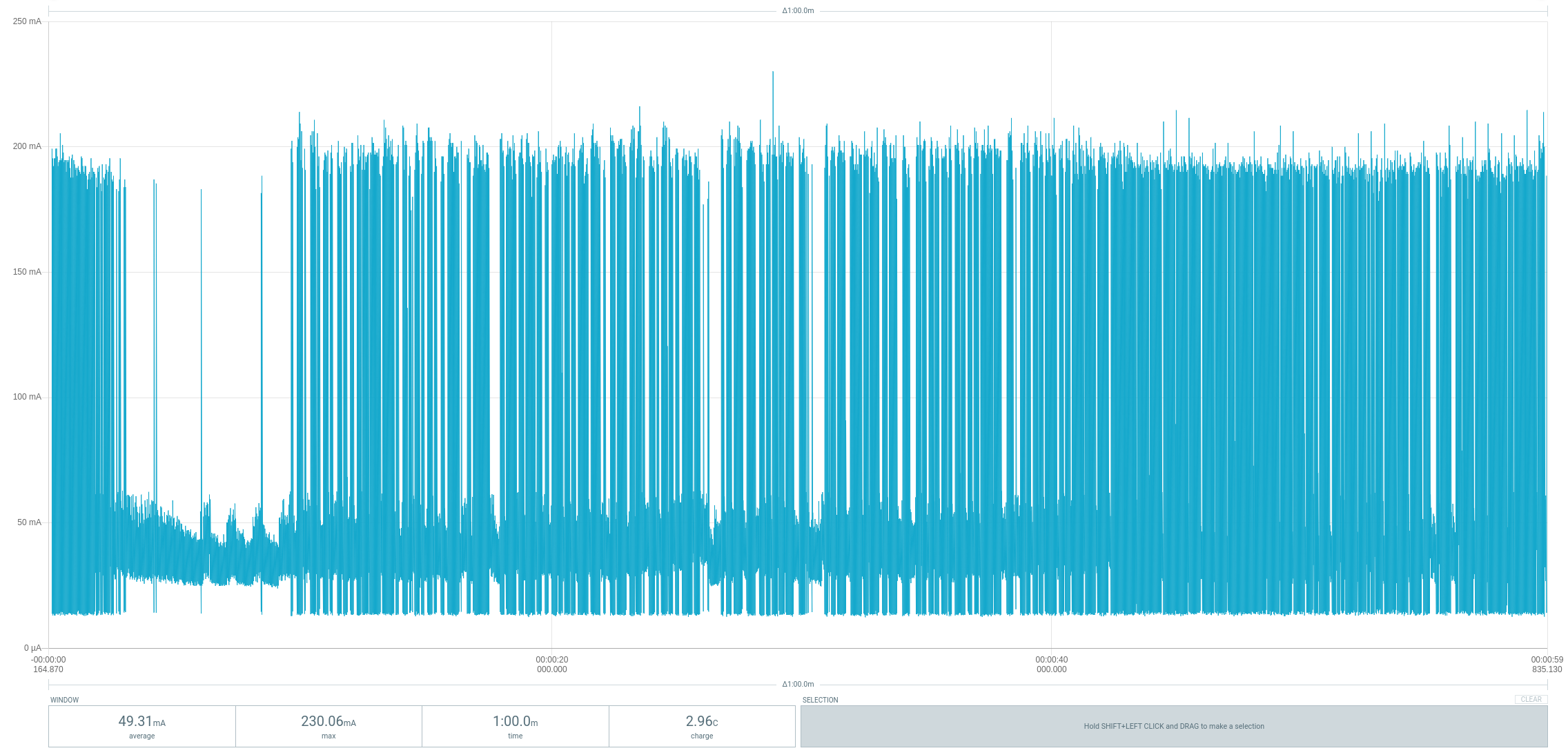
TinyPlayer consumes an average of 50mA at 3.7V at medium volume and a connected 4Ohm/3W speaker. A 300mAh battery enables a playing time of about 6 hours.
- ATtiny13A datasheet
- DFPLayer Mini datasheet
- TSOP4838 datasheet
- MCP73831 datasheet
- IR Receiver Implementation
- TinyRemote
- TinyDFPlayer based on ATtiny85

This work is licensed under Creative Commons Attribution-ShareAlike 3.0 Unported License. (http://creativecommons.org/licenses/by-sa/3.0/)