Notion notes link - https://satvik3799.notion.site/Physical-Design-using-OpenLANE-with-Sky130-PDK-dfa6e85766e14a88ab9e8596e87e42c Notion Lab detailed Guide link - https://satvik3799.notion.site/Results-only-e5cbc0e146e84fe3a0bf72ced4c87?pv=4
To see at which step the current def file is, use the command echo ::env(CURRENT_DEF) and it will give the current def file.
Move back up to Table of contents
-
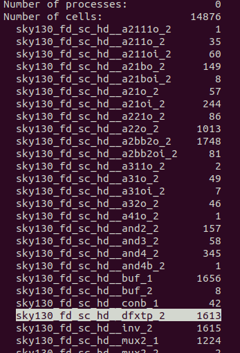
For default Picorc32a design:
$Flop \ ratio = \frac{no. \ of \ D-flip-flops \ used}{no. \ of \ cells \ used.}$ here, flop ratio = 1613/14876 = 0.1084
Chip area for module:
$147712.918400 \ \mu m^2$ 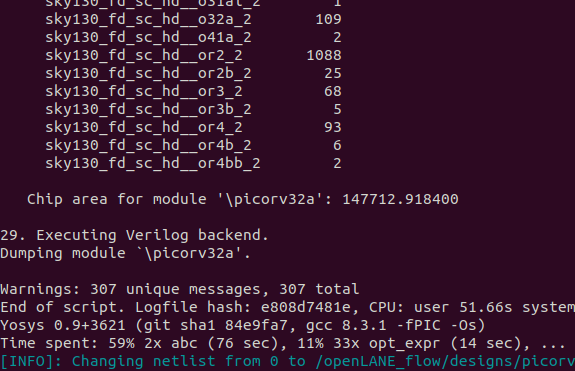
-
For custom standard cell added Picorv32a design:
The statistics report of the synthesis is can be found here -
Flop ratio = 1613/20121 = 0.08016
Chip area module -
$196832.528 \ \mu m^2$ 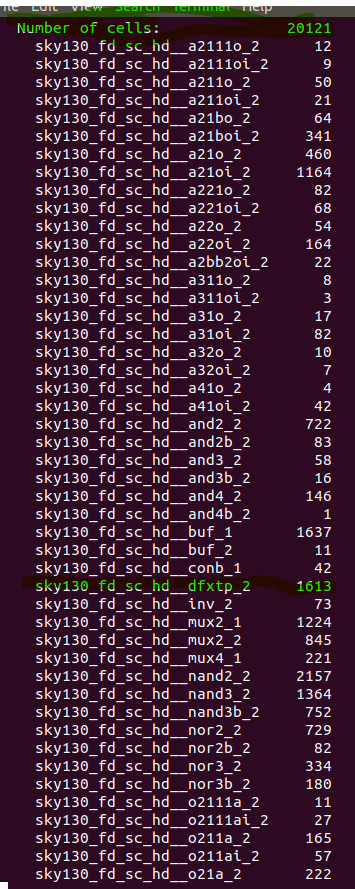


Move back up to Table of contents
For custom standard cell added Picorv32a design: The new generated .def file after running floorplan can be found here: floorplan.def
Config.tcl file contents:
Notice the utilization factor used.
# Design
set ::env(DESIGN_NAME) "picorv32a"

set ::env(VERILOG_FILES) "./designs/picorv32a/src/picorv32a.v"
set ::env(SDC_FILE) "./designs/picorv32a/src/picorv32a.sdc"

set ::env(CLOCK_PERIOD) "12.000"
set ::env(CLOCK_PORT) "clk"

set ::env(CLOCK_NET) $::env(CLOCK_PORT)
set ::env(FP_CORE_UTIL) 40
set ::env(FP_IO_VMETAL) 4
set ::env(FP_IO_HMETAL) 3

set ::env(LIB_SYNTH) "$::env(OPENLANE_ROOT)/designs/picorv32a/src/sky130_fd_sc_hd__typical.lib" //notice double underscore before typical, fast and slow.
set ::env(LIB_FASTEST) "$::env(OPENLANE_ROOT)/designs/picorv32a/src/sky130_fd_sc_hd__fast.lib"
set ::env(LIB_SLOWEST) "$::env(OPENLANE_ROOT)/designs/picorv32a/src/sky130_fd_sc_hd__slow.lib"
set ::env(LIB_TYPICAL) "$::env(OPENLANE_ROOT)/designs/picorv32a/src/sky130_fd_sc_hd__typical.lib"

set ::env(EXTRA_LEFS) [glob $::env(OPENLANE_ROOT)/designs/$::env(DESIGN_NAME)/src/*.lef]

set filename $::env(OPENLANE_ROOT)/designs/$::env(DESIGN_NAME)/$::env(PDK)_$::env(STD_CELL_LIBRARY)_config.tcl
if { [file exists $filename] == 1} {
	source $filename
}
Floor plan result:

Notice the equi-distant IO pads which are set manually via the tcl command:

Zoomed in view of the cells:

The Standard cell are placed at the bottom left temporarily.

Move back up to Table of contents
For custom standard cell added Picorv32a design:
Placement .def file can be found here: placement.def
To view the file in magic tool, the general command is
magic -T <location and name of the .tech file of the PDK> lef read <location and name of the merged.lef file generated while preparing the design> read def <location and name of the def file>
Placement result:

The separately included standard cell - sky130_vsdinv

Zoomed in cells.

Move back up to Table of contents
The new generated .def file after running CTS, with added clock buffers can be found here: picorv32a.cts.def

After running the Clock Tree Synthesis, the .def layout files gets updated along with synthesis.v file.

The .def file after CTS:

Move back up to Table of contents
The Power and Ground nets get generated in this step. After running the command gen_pdn , the number of VPWR and VGND nodes generated can be seen.
The new generated .def file can be found here: pdn.def

Results and .def file view in magic tool.

Move back up to Table of contents
Manually set Routing strategy is 0. set ::env(ROUTING_STRATEGY) 0.
The generated .def file and the extracted SPEF file can be found here: picorv32a.def
Routing takes time and uses memory. The current design was completed in ******1Hr14Min42Sec, ************and used 842 MB.


Completed routing at 57th iterations, with zero violations in routing.

The command has also ran SPEF extraction.

Routing stats with layers:

.def file output opened in Magic:

Move back up to Table of contents
The gds file can be found here -
The .mag file can be found here -

Zoomed in view of the file.

Move back up to Table of contents
Get the .mag file of a cell and extract its SPICE model.
Use magic to open the .mag file.

Extract the SPICE file using these commands in tkcon console:
extract all
ext2spice cthresh 0 rthresh 0
ext2spice

Create a SPICE deck and Run a transient simulation of the SPICE file. The netlist and spice simulation parameters along with pmos and nmos paramters are as follows:
* SPICE3 file created from sky130_inv.ext - technology: sky130A

.option scale=0.01u
.include ./libs/pshort.lib
.include ./libs/nshort.lib

//.subckt sky130_inv A Y VPWR VGND
//X0 Y A VGND VGND sky130_fd_pr__nfet_01v8 ad=1.44n pd=0.152m as=1.37n ps=0.148m w=35 l=23
//X1 Y A VPWR VPWR sky130_fd_pr__pfet_01v8 ad=1.44n pd=0.152m as=1.52n ps=0.156m w=37 l=23

M1000 Y A VPWR VPWR pshort_model.0 ad=1.44n pd=0.152m as=1.37 ps=0.148 w=35 l=23
M1001 Y A VGND VGND nshort_model.0 ad=1.44n pd=0.152m as=1.52 ps=0.156 w=37 l=23
VDD VPWR 0 3.3V
VSS VGND 0 0V
Va A VGND PULSE(0V 3.3V 0 0.1ns 0.1ns 2ns 4ns)

C0 VPWR Y 0.117fF
C1 A Y 0.0754fF
C2 A VPWR 0.0774fF
C3 Y VGND 0.279fF
C4 A VGND 0.45fF
C5 VPWR VGND 0.781fF

.tran 1n 20n
.control
run
.endc
.end
Running simulation with command ngspice sky130_inv.spice will generate a matrix of different values according to KCL and KVL equations. Running the command plot y vs time a in the ngspice console gives the following results:

Characterization of the custom inverter based on Rise transition, Fall transition, Cell Rise delay and Cell fall delay.
20% of 3.3V = 0.66V
50% of 3.3V = 1.65V
80% of 3.3V =2.64V
X-axis is the time axis and Y-axis is the Voltage.
Red line - Output
Blue line - Input
Rise Transition: Time taken for the output to rise from 20% to 80% of max value.

Rise transition = (Time to reach 2.6V) - (Time to reach 0.66V) = 2.23529 - 2.17647 = 0.058 ns
Fall Transition: Time taken for the output to fall from 80% to 20% of max value .

Fall transition = 4.0672 - 4.0396 = 0.0276 ns
Cell Rise delay: difference in time(50% output rise) to time(50% input fall).

Cell rise delay = 2.18228 - 2.1557 = 0.02658 ns
Cell Fall delay: difference in time(50% output fall) to time(50% input rise).

Cell fall delay = 4.05467 - 4.04467 = 0.01 ns
The I/O, and power ports should be at intersection of horizontal and vertical tracks. The CMOS Inverter ports A and Y are on li1 layer. It needs to be ensured that they're on the intersection of horizontal and vertical tracks. We access the tracks.info file for the pitch and direction information:

Set the grid parameters according to the file in the tkcon console:
grid 0.46um 0.34um 0.23um 0.17um
A LEF file of the custom standard cell is extracted using the lef write command in the tkcon console, which creates a .lef file.
To integrate the custom standard cell in OpenLane config.tcl file must be edited with the following commands:
set ::env(LIB_SYNTH) "$::env(OPENLANE_ROOT)/designs/picorv32a/src/sky130/sky130_fd_sc_hd__typical.lib"
set ::env(LIB_SLOWEST) "$::env(OPENLANE_ROOT)/designs/picorv32a/src/sky130/sky130_fd_sc_hd__slow.lib"
set ::env(LIB_FASTEST) "$::env(OPENLANE_ROOT)/designs/picorv32a/src/sky130/sky130_fd_sc_hd__fast.lib"
set ::env(LIB_TYPICAL) "$::env(OPENLANE_ROOT)/designs/picorv32a/src/sky130/sky130_fd_sc_hd__typical.lib"

set ::env(EXTRA_LEFS) [glob $::env(OPENLANE_ROOT)/designs/$::env(DESIGN_NAME)/src/*.lef]
When the OpenLane in invoked, after design preparation stage use the following commands to have the cell integrated into the design.
set lefs [glob $::env(DESIGN_DIR)/src/*.lef]
add_lefs -src $lefs
and then run the synthesis with run_synthesis command. Which will include the new cell in the design. The results of cell integration are here: