(Updated May 31, 2022)
Received the V2.0 PCBs yesterday. First modifications (Not shown on the schematic):
- Led resistors (R13, R16): 1 kOhms instead of 220 Ohms (the LEDs are way too bright).
- Thermistor 10 kOhms resistor R11 hooked to GPIO25 instead of 3.3V using a wire: To diminish thermistor heath effect on reading values, the GPIO25 is put high only at thermistor read time.
The thermistor is only used when the device is connected to an external source of power: to get an accurate 3.3v source for thermistor read-outs.
To compensate for the lack of linearity of the ESP32 A2D, a lookup table has been generated and used by the software (ESPHome). See the generator here: software/lut_gener.ino Pins 34 and 25 must be connected before using the generator (without the GPIO34 resistor). Must be used for each ESP32 instance (will be different for each ESP32 chip). An example of the generated table can be found here: software/.freezer_adc_lut.h.
An ESPHome example of use to sense a Freezer is supplied in software/freezer.yaml.
(Updated May 19, 2022)
The new version is ready for production. Here are the modifications from version 1.0:
- Sensors using GPIO 15 (Generic sensor), 25 (thermistor) and 27 (light sensor) migrated to GPIO 32, 34 and 35 respectively
- Added I2C interface
- Added program-controlled led
- All parts are aligned in the same direction onboard, to simplify hand soldering
- The board is 0.6mm larger
(Updated May 18, 2022)
The thermistor and photo-resistor sensors are working well. As they use GPIO 25 and 27 A2D capability (ADC2), the WiFi interface cannot be enabled at the same time the sensors are being read: the ADC2 electronics is shared with the onboard WiFi capability. An updated version of the device is being prepared to use ADC1 GPIOs instead. (This has been corrected in version 2.0)
(Updated May 17, 2022)
All the trials are positive so far. For R1, instead of 10K, I'm using 2.7M ohms. Remains the thermistor and photo-resistor sensors to try.
(Updated March 29, 2022)
Initial release.
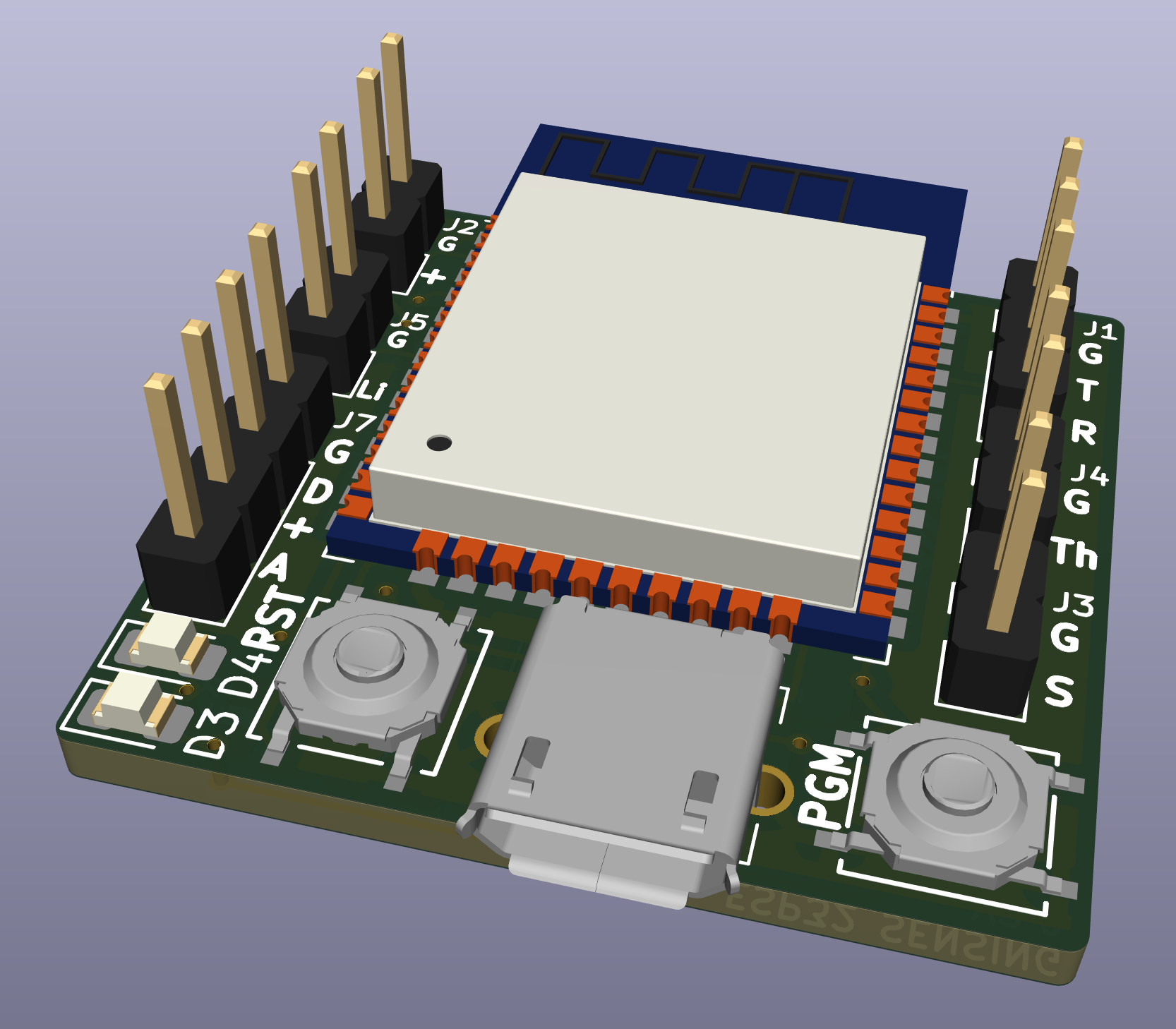
This is a small footprint ESP32-based sensing device, with the following characteristics:
- 30x28 mm circuit board (30x40 mm with ESP32 antenna)
- Two power modes:
- Battery (AAx2) (through external battery case)
- External 5 Volts power support (through power-only Micro USB-B port)
- Battery level monitoring circuit
- Three Sensing ports:
- Multi-Purpose (configurable through Resistor and Capacitor parts)
- Thermistor (https://learn.adafruit.com/thermistor/using-a-thermistor)
- Photoresistor (https://learn.adafruit.com/photocells/using-a-photocell)
- I2C Interface port
- External FTDI port (through a 3-pins [GND, RxD, TxD] port) (https://learn.adafruit.com/ftdi-friend)
- RST / PGM buttons
- Power LED (for external power only)
- Programmable LED
- Designed with KiCAD V6.0.5 (https://www.kicad.org)
- Public Domain
The choice of components is related to their availability in my inventory.
Looking at the schematic, you will find here the information related to each subsection present on the device. Some subsections are required, and others are optional depending on your needs.
The electronic component identifiers required for each subsection are listed inside square brackets.
- ESP-WROOM-32 [U1] - This is the processor in use on the device.
- RESET Button [SW2, R6, C1] - Required to maintain the processor working and do a reset when it is required to take back the control for programming or when the device is not behaving properly.
- PGM Button [SW1, R5] - For programming the processor, the PGM Button must be pressed as the reset button is also pressed, and then released after releasing the reset button, such that the processor will be put in program loading. The FTDI interface must be connected to the computer to transmit the new program.
- FTDI [D2, J1] - This is the connection to an external FTDI device that allows for communication between the ESP32 processor and a development PC for program loading and debugging output. Connector's pins are labeled G (Ground), R (RxD), and T (TxD) relative to the ESP32 pinout: The External FTDI GND pin must be connected to G, the FTDI RxD pin must be connected to T, and the FTDI TxD pin must be connected to R. Power must be supplied to the board through AA batteries or an external power supply.
- AAx2 Battery Connector [J2] - If power is to be supplied with AA batteries, the connector is required. The battery holder wires can also be directly soldered in the through-holes. Please respect the polarity (a '+' sign is present on the board to indicate the positive wire location). Do not connect any battery if you intend to use an external power supply.
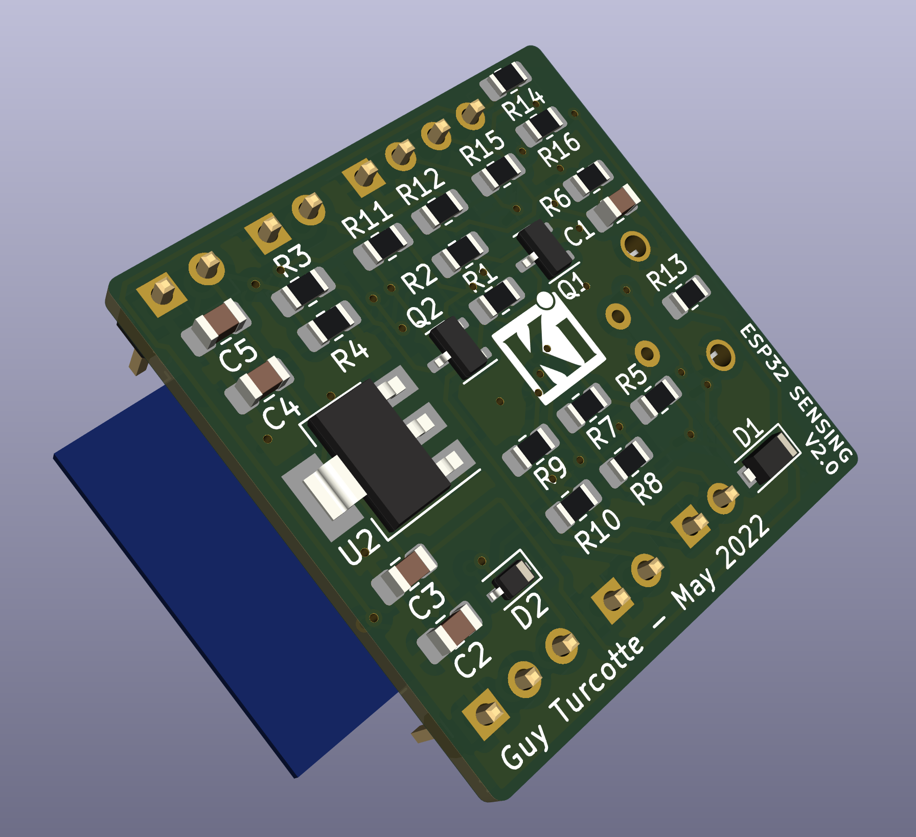
- External 5V Power, [U2, J6, D1, D3, R13, C2, C3, C4, C5] - This is a linear 3.3V regulator circuit, only required when a DC 5 Volts power supply is used. It is expected that the power supply is using a male micro USB-B connector. Do not implement this subsection if you intend to use batteries.
- Voltage Monitoring [Q1, Q2, R1, R2, R3, R4] - This circuit will allow for reading the 3.3 V power voltage for the device through ADC1_0 internal to the ESP32. If AA batteries are used, it will allow monitoring the battery level to replace them when required. The MOSFET transistor [Q2] insure that the circuit will not take a load on the batteries. Must be enabled through [Q1] using GPIO17.
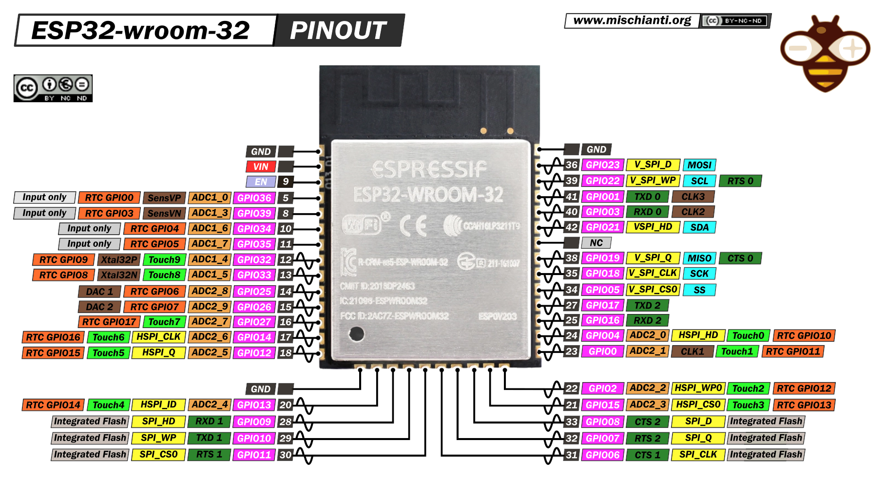
- Generic Sensor Input [J3, R7, R8, R9, R10] - This is a port to retrieve some sensor information. The four resistors must be adjusted to consider the kind of sensing to be done (pull-up, pull-down, etc.). Some resistor locations can be used for capacitors if required (e.g. adding an RC circuit). This sensor is connected to GPIO32 (ADC1_4) of the ESP32. The J3 pins are labeled 1: G (Gnd), 2: S (Signal).
- Heat Sensor [J4, R11] - Allow for reading the level of Heat using an external thermistor through an A2D of the processor (ADC1). This sensor is connected to GPIO34 (ADC1_6) of the ESP32. Can be used with another kind of sensor as appropriate. The J4 pins are labeled 1: G (Gnd), 2: Th (Signal).
- Light Sensor [J5, R12] - Allow for reading the level of Heat using an external photoresistor through an A2D of the processor (ADC1). This sensor is connected to GPIO35 (ADC1_7) of the ESP32. Can be used with another kind of sensor as appropriate. The J5 pins are labeled 1: G (Gnd), 2: Li (Signal).
- I2C Interface [J7, R14, R15] - Used to connect to external I2C devices (displays, sensors, etc). Connected to the ESP32 through GPIO21 (SDA) and GPIO22 (SCL). The J7 connector offers 3.3v and GND pins. Resistors may have to be adjusted depending on the load. The J7 Pins are labeled 1: G (ground), 2: D (SDA), 3: + (3.3v), 4: C (SCL)
- Program Controlled LED [D4, R16] - Could be useful for debugging purpose. Not a good idea to use it on battery-powered devices. Connected to ESP32 GPIO12. Important: Must be programmed as an output GPIO.
-
The thermistor and photoresistive interfaces are exploratory. The known lack of linearity of the ESP32 A2D may have an impact on the quality of the retrieved data. See here, and here for further information.
-
The Micro USB-B connector is a specific part with only 2 through-hole pins (GND and 5V). See the BOM below for purchase locations. On Amazon, there are 100, 30, and 10 pieces bundles available. A more conventional 5-pins connector may be adapted (physical tweak or modification to the board design).
-
The Power LED is for use only with the external power supply and is hooked on the 5v side of the linear regulator. It could have been hooked to the 3.3v side, closer to the ESP32.
-
The linear 3.3v regulator capacitors may have to be different than the one selected. In particular, on the output side, to get a better transient response, a 22uF tantalum may replace the one indicated (per the AMS1117 spec sheet).
-
Using batteries to power the device: depending on the processor speed and the networking requirements at startup (WiFi, BT, BLE), the AA batteries may not be able to supply the required startup current (100 to 500 mA). Many options are possible: use larger batteries, lithium instead of alkaline, and add some capacitors (tantalum or other) at C4/C5 locations.
| Reference(s) | Value | Footprint | Where to find |
|---|---|---|---|
| C1 | .1uF | 0805 | |
| C2, C5 | 10uF | 0805 | |
| C3, C4 | 100nF | 0805 | |
| D1 | MBR120VLSF or equivalent | SOD-123 | e-Radionica, Digikey, Mouser |
| D2 | 1N4148WS | SOD-323 | Digikey, Mouser |
| D3, D4 | LED | 0805 | |
| J1 | Connector 1x3 | Pin Header 2.54mm | |
| J2, J3, J4, J5 | Connector 1x2 | Pin Header 2.54mm | |
| J6 | Micro-B USB | AliExpress, Amazon | |
| J7 | Connector 1x4 | Pin Header 2.54mm | |
| Q1 | MMBT3904 | SOT-23 | |
| Q2 | NDS356AP or IRLML5103TRPBF or equivalent | SOT-23 | |
| R1, R3 to R7, R10 to R12 | 10k ohms | 0805 | |
| R2 | 1k ohms | 0805 | |
| R8, R9 | 0 ohms | 0805 | |
| R13, R16 | 220 ohms | 0805 | |
| R14, R15 | 3.3k ohms | 0805 | |
| SW1, SW2 | PTS526_SK15_SMTR2_LFS | SMTR2 | Mouser, Digikey, e-Radionica |
| U1 | ESP-WROOM-32 | e-Radionica | |
| U2 | AMS1117-3.3 | SOT-223-3 |
Permission is hereby granted, free of charge, to any person obtaining a copy of this project and associated documentation files (the "Project Content"), to deal in the Project without restriction, including without limitation the rights to use, copy, modify, merge, publish, distribute, sublicense, and/or sell copies of the Project Content, and to permit persons to whom the Project Content is furnished to do so, subject to the following conditions:
The above copyright notice and this permission notice shall be included in all copies or substantial portions of the Project Content.
THE PROJECT CONTENT IS PROVIDED "AS IS", WITHOUT WARRANTY OF ANY KIND, EXPRESS OR IMPLIED, INCLUDING BUT NOT LIMITED TO THE WARRANTIES OF MERCHANTABILITY, FITNESS FOR A PARTICULAR PURPOSE, AND NON-INFRINGEMENT. IN NO EVENT SHALL THE AUTHORS OR COPYRIGHT HOLDERS BE LIABLE FOR ANY CLAIM, DAMAGES, OR OTHER LIABILITY, WHETHER IN AN ACTION OF CONTRACT, TORT OR OTHERWISE, ARISING FROM, OUT OF OR IN CONNECTION WITH THE PROJECT CONTENT OR THE USE OR OTHER DEALINGS IN THE PROJECT CONTENT.


