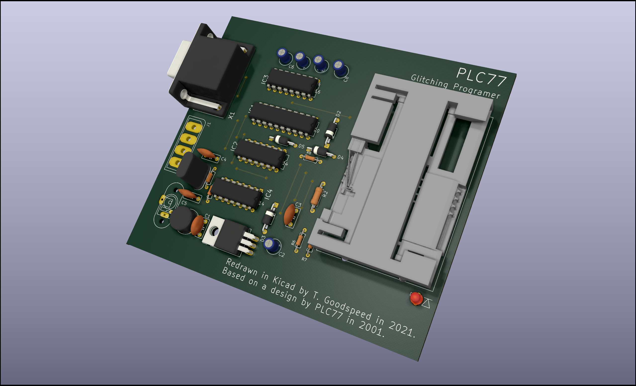
Howdy y'all,
As I write this in 2021, glitching is all the rage in hardware security again, but twenty years ago in the satellite TV cracking community it was just as popular, with hand-etched PCBs of through-hole components being used to glitch smart cards and freely watch TV.
As Tripod begins to bitrot and this history slowly becomes lost to us, I thought I'd grab an old glitcher from a Tripod website, convert it to Kicad, and maybe assemble a few glitchers from that age. This one is by LPC77, dating from April of 2001.
--Travis
The root directory is a Kicad project, restored from the original design but without modernizations such as surface-mount componenets that would alter its asthetics.
The past directory contains the published source files, originally
in Eagle's old binary format. I used Eagle 6.6.0 under Wine to
convert the files into the modern XML format, which Kicad can freely
import.
Revisons: I have increased the length of the circuit board by 1/2 inch to allow for a less cluttered layout.
I moved the surface mount resistors nearer to the thru hole types.
I also (the Most Significant change) modified the oscilator circuit to add a resistor(R6) and change the value of R1, making the output wave form much better.
Parts list and Notes
1 ISO card socket of your choosing
1 9 pin female D sum min connector (X2)
2 1n4004 diodes (D2, D3)
2 1n914 or 1n4148 diodes (D4, D5)
1 red/dreen led (two lead type) (D1)
1 90S2313p-10 atmel processor (IC1)programmed with bl.hex
1 MAX232 (IC3)
1 74HC00 (IC4)
1 7405 (IC2)
1 7805T (U1)
1 bridge rectifyer (B1)
2 .1uf cap (C1, C3)
2 27pf cap (C4, C5)
1 35uf to 100 uf Cap 16v min (C2)
4 10 uf 16v cap (C6, C8, C9, C10)
2 430 to 475 ohm resister(R3 or R3a,R4 or R4a)
1 1 Meg ohm resister (R1 or R1a)
1 33ohm 1/2 watt resister (R2)
1 1K to 2.2K resister (R5 or R5a)
1 2.2K resister (R6 or R6a)
1 3.57595 mhz Crystal (Q1)
This programmer is intended to be used as a standalone Phoenix type ISO programmer with the ability to use the Atmel Chip from the Simpleboot product to allow operation with H cards that have suffered the Black Sunday ECM.
If non Glitching operation is desired, simply do not install the Atmel IC and put a jumper wire from pin 12 to 13 of that atmels socket.
It is designed to be built on a single sided pcb but there are a few jumpers that must be installed.
The original one used surface mounted resister and i have added provisions for thru hole parts, use one or the other not both!
I recommend that all the ICs be socketed.
If you wish to power the programmer from the PC, use a pc power extension from Radio Shack and cut off one of the male plugs and attach the red wire to the pad which goes to the diode and the black wires to the two center pads, the yellow wire it not used but may be soldered to the pad provided.
If powered from PC, the bridge, regulator and associated parts may be removed.
I designed the layout to fit the four inch wide opening typical of the diskette drive in a PC. I mounted a programer on the plastic type adapter used to mount a diskette drive in a 5 1/4 inch bay of a PC with great success.
In an AT type PC it is possible to attach the comm port from the motherboard to the internally mounted by moving the connector from the pc's back panel or slot cover. This make for a very neat Emulation setup.
I have added a slightly modified layout to the package that may be a little easier to build as it is a little larger and not so crowded. Take a look at Glitchprog1LedB.brd, the schematic is identical so i did not duplicate it.
This is my first attempt at releasing a design so pardon my errors. Your comments are appreiciated, I will learn from them.
PLC77
