Depend on your use case, for esp32, the robot can run micro ros wifi transport without a robot computer (eg Pi 4) on it. All the software will be installed on your desktop computer. In other case, all software mentioned in this guide should be installed on the robot computer.
It is assumed that you already have ROS2 and linorobot2 package installed. If you haven't, go to linorobot2 package for installation guide.
cd $HOME
git clone https://github.com/linorobot/linorobot2_hardware -b $ROS_DISTRO
Download and install platformio. Platformio allows you to develop, configure, and upload the firmware without the Arduino IDE. This means that you can upload the firmware remotely which is ideal on headless setup especially when all components have already been fixed.
python3 -c "$(curl -fsSL https://raw.githubusercontent.com/platformio/platformio/master/scripts/get-platformio.py)"
Add platformio to your $PATH:
echo "PATH=\"\$PATH:\$HOME/.platformio/penv/bin\"" >> $HOME/.bashrc
source $HOME/.bashrc
Download the udev rules from Teensy's website:
wget https://www.pjrc.com/teensy/00-teensy.rules
and copy the file to /etc/udev/rules.d :
sudo cp 00-teensy.rules /etc/udev/rules.d/
sudo apt install screen
Robot Orientation:
-------------FRONT-------------
WHEEL1 WHEEL2 (2WD)
WHEEL3 WHEEL4 (4WD)
--------------BACK--------------
If you're building a 2 wheel drive robot, assign MOTOR1 and MOTOR2 to the left and right motors respectively.
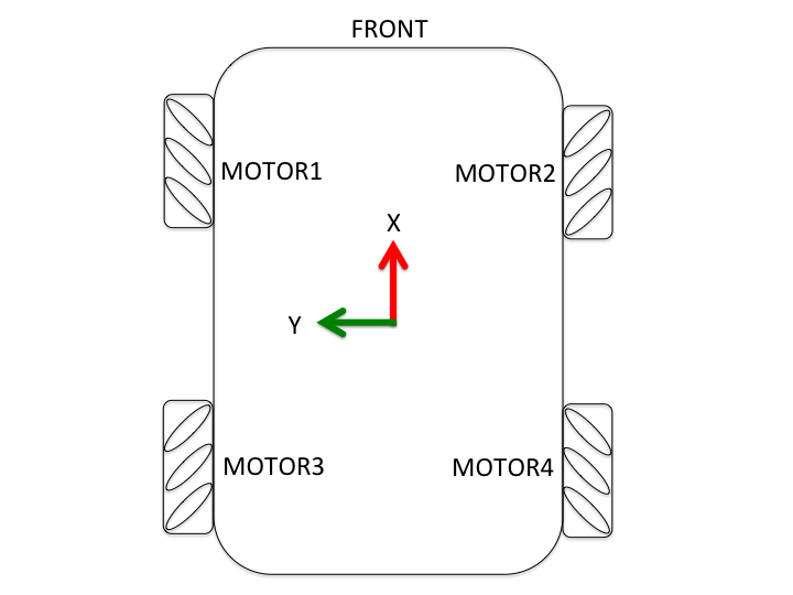
For mecanum robots, follow the wheels' orientation below.
Supported Motor Drivers:
-
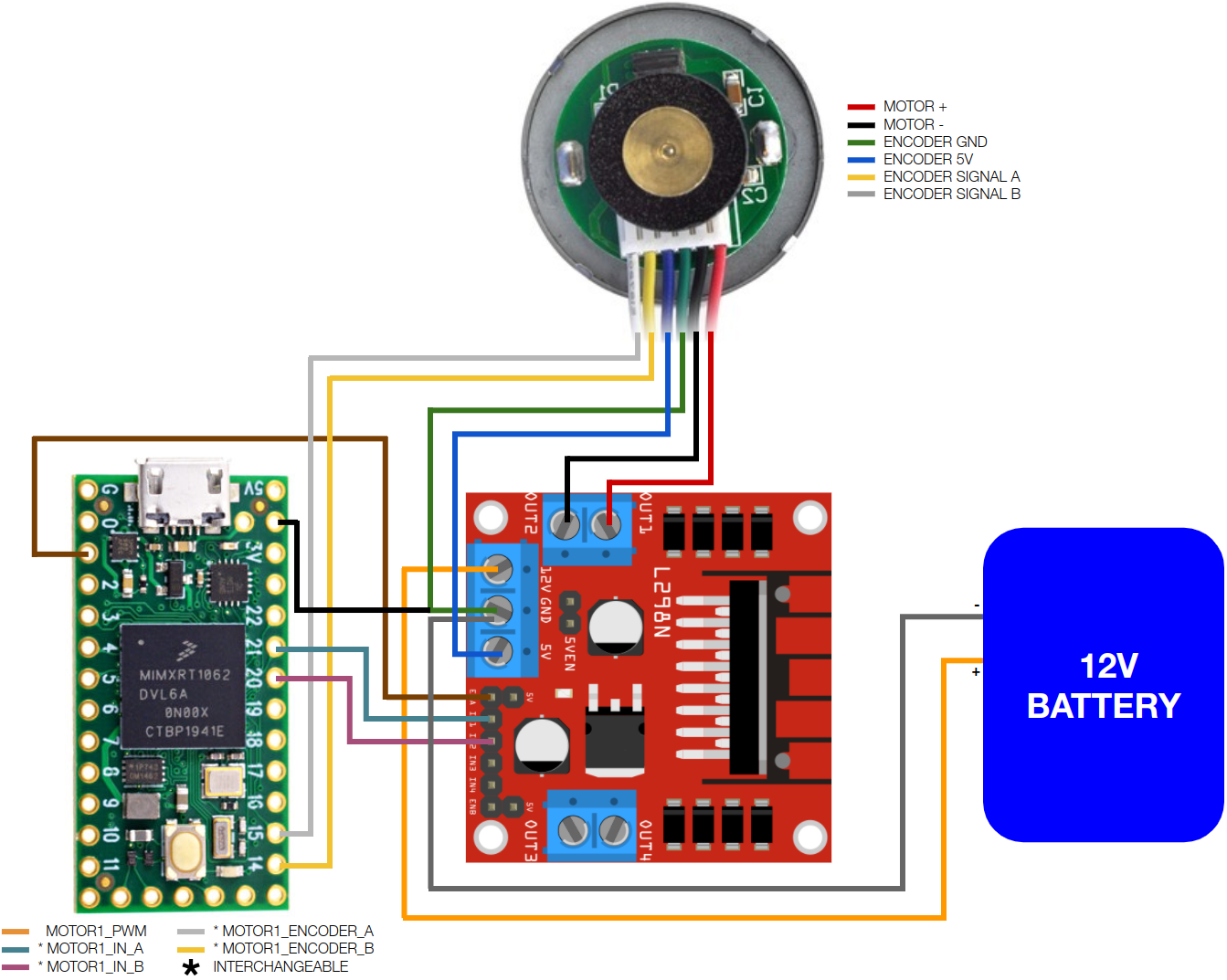
GENERIC_2_IN_MOTOR_DRIVER - Motor drivers that have EN (pwm) pin, and 2 direction pins (usually DIRA, DIRB pins). Example: L298 Breakout boards.
-
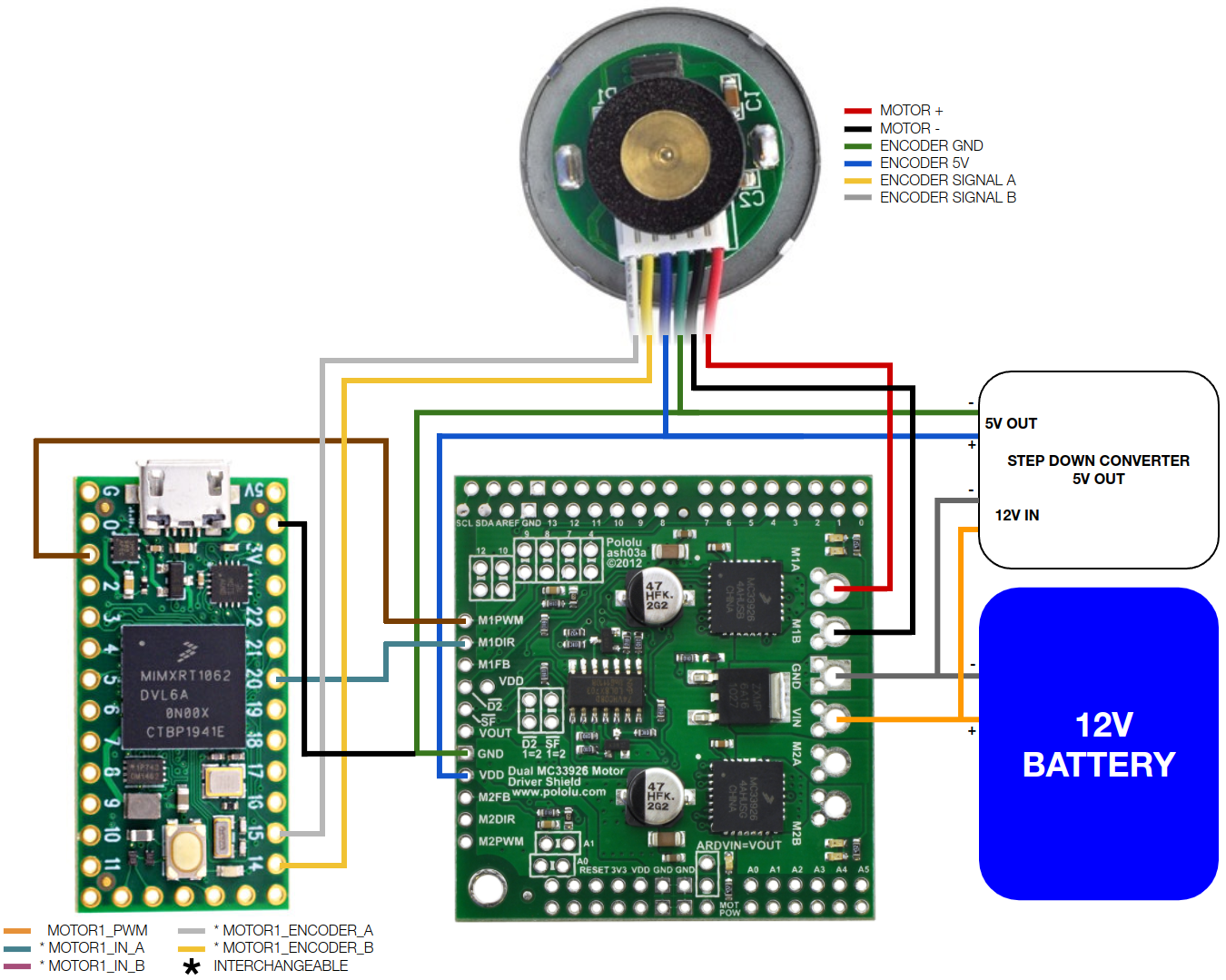
GENERIC_1_IN_MOTOR_DRIVER - Motor drivers that have EN (pwm) pin, and 1 direction pin (usual DIR pin). These drivers usually have logic gates included to lessen the pins required in controlling the driver. Example: Pololu MC33926 Motor Driver Shield.
-
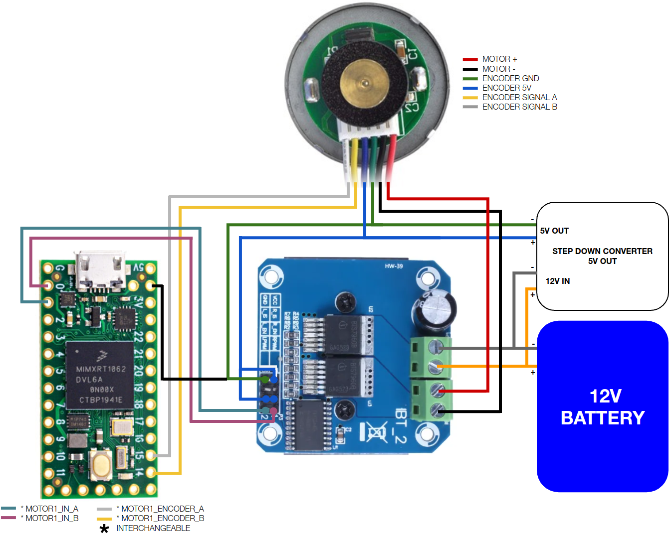
BTS7960_MOTOR_DRIVER - BTS7960 motor driver.
-
ESC_MOTOR_DRIVER - Bi-directional (forward/reverse) electronic speed controllers.
The motor drivers are configurable from the config file explained in the later part of this document.
Supported IMUs:
- GY-85
- MPU6050
- MPU9150
- MPU9250
Supported MAGs:
- HMC5883L
- AK8963
- AK8975
- AK09918
- QMC5883L
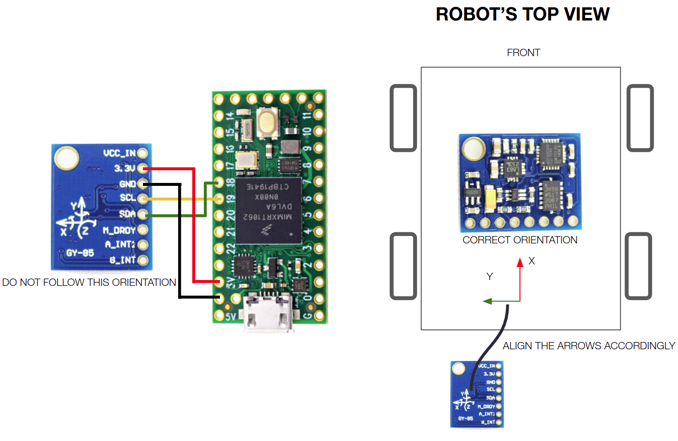
Below are connection diagrams you can follow for each supported motor driver and IMU. For simplicity, only one motor connection is provided but the same diagram can be used to connect the rest of the motors. You are free to decide which microcontroller pin to use just ensure that the following are met:
-
Reserve SCL0 and SDA0 (pins 18 and 19 on Teensy boards) for IMU.
-
When connecting the motor driver's EN/PWM pin, ensure that the microcontroller pin used is PWM enabled. You can check out PJRC's pinout page for more info.
Alternatively, you can also use the pre-defined pin assignments in lino_base_config.h. Teensy 3.x and 4.x have different mapping of PWM pins, read the notes beside each pin assignment in lino_base_config.h carefully to avoid connecting your driver's PWM pin to a non PWM pin on Teensy.
All diagrams below are based on Teensy 4.0 microcontroller and GY85 IMU. Click the images for higher resolution.
Take note of the IMU's correct orientation when mounted on the robot. Ensure that the IMU's axes are facing the correct direction:
- X - Front
- Y - Left
- Z - Up
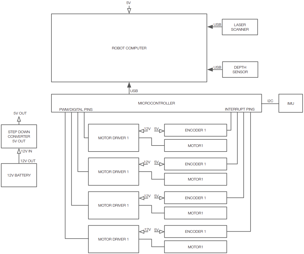
Reference designs you can follow in building your robot.
A minimal setup with a 5V powered robot computer.
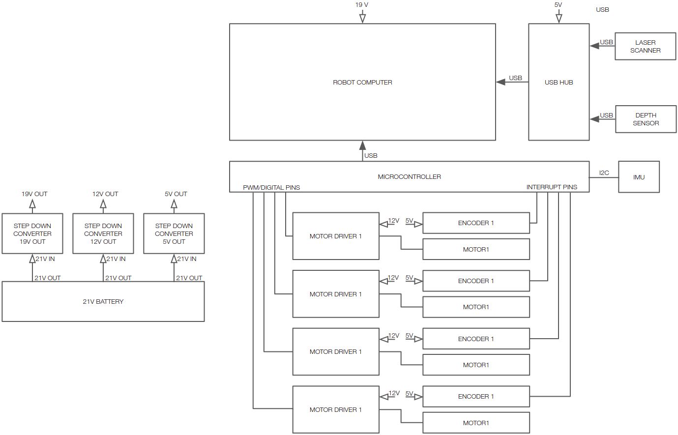
A more advanced setup with a 19V powered computer and USB hub connected to sensors.
For bigger robots, you can add an emergency switch in between the motor drivers' power supply and motor drivers.
After installed the build enviroment, before touching any code, try building a sample firmware to verify everything is setup properly.
cd firmware
pio run -e teensy41
# Or if you are using esp32
pio run -e esp32
Then create a custom configuration for your robot. This will minimize the merge conflicts from future pulling the upstream. Add an entry to the end of platformio.ini. Add an entry to ../config/config.h before the LINO_BASE. Take the lino_base_config.h as a template and add your custom configuration file to ../config/custom/ . Make changes to your custom configuration file. The following is an example for esp32 project.
platformio.ini
[env:myrobot]
platform = espressif32
board = esp32dev
board_build.f_flash = 80000000L
board_build.flash_mode = qio
upload_port = /dev/ttyUSB0
upload_protocol = esptool
lib_deps =
    ${env.lib_deps}
    https://github.com/RoboticsBrno/ServoESP32
    https://github.com/madhephaestus/ESP32Encoder
build_flags =
    -I ../config
    -D USE_MYROBOT_CONFIG
../config/config.h
#ifdef USE_DEV_CONFIG
    #include "custom/dev_config.h"
#endif

// Add myrobot here
#ifdef USE_MYROBOT_CONFIG
    #include "custom/myrobot_config.h"
#endif

// this should be the last one
#ifndef LINO_BASE
    #include "lino_base_config.h"
#endif
../config/custom/myrobot_config.h
#ifndef MYROBOT_CONFIG_H
#define MYROBOT_CONFIG_H

#define LED_PIN 2 //used for debugging status
...
...
#endif
Open your custom configuration file. Uncomment the base, motor driver and IMU you want to use for your robot. For example:
#define LINO_BASE DIFFERENTIAL_DRIVE
#define USE_GENERIC_2_IN_MOTOR_DRIVER
#define USE_GY85_IMU
Constants' Meaning:
ROBOT TYPE (LINO_BASE)
-
DIFFERENTIAL_DRIVE - 2 wheel drive or tracked robots w/ 2 motors.
-
SKID_STEER - 4 wheel drive robots.
-
MECANUM - 4 wheel drive robots using mecanum wheels.
MOTOR DRIVERS
-
USE_GENERIC_2_IN_MOTOR_DRIVER - Motor drivers that have EN (pwm) pin, and 2 direction pins (usually DIRA, DIRB pins).
-
USE_GENERIC_1_IN_MOTOR_DRIVER - Motor drivers that have EN (pwm) pin, and 1 direction pin (usual DIR pin). These drivers usually have logic gates included to lessen the pins required in controlling the driver.
-
USE_BTS7960_MOTOR_DRIVER - BTS7960 motor driver.
-
USE_ESC_MOTOR_DRIVER - Bi-directional (forward/reverse) electronic speed controllers.
INERTIAL MEASUREMENT UNIT (IMU)
-
USE_GY85_IMU - GY-85 IMUs.
-
USE_MPU6050_IMU - MPU6060 IMUs.
-
USE_MPU9150_IMU - MPU9150 IMUs.
-
USE_MPU9250_IMU - MPU9250 IMUs.
-
USE_HMC5883L_IMU - HMC5883L MAGs.
-
USE_AK8963_MAG - AK8963 MAGs.
-
USE_AK8975_MAG - AK8975 MAGs.
-
USE_AK09918_MAG - AK09918 MAGs.
-
USE_QMC5883L_MAG - QMC5883L MAGs.
-
MAG_BIAS - Magnetometer calibration, eg { -352, -382, -10 }.
Next, fill in the robot settings accordingly:
#define K_P 0.6
#define K_I 0.8
#define K_D 0.5

#define MOTOR_MAX_RPM 100
#define MAX_RPM_RATIO 0.85
#define MOTOR_OPERATING_VOLTAGE 24
#define MOTOR_POWER_MAX_VOLTAGE 12
#define MOTOR_POWER_MEASURED_VOLTAGE 11.7

#define COUNTS_PER_REV1 2200
#define COUNTS_PER_REV2 2200
#define COUNTS_PER_REV3 2200
#define COUNTS_PER_REV4 2200

#define WHEEL_DIAMETER 0.09
#define LR_WHEELS_DISTANCE 0.2

#define PWM_BITS 10
#define PWM_FREQUENCY 20000
Constants' Meaning:
-
K_P, K_I, K_D - PID constants used to translate the robot's target velocity to motor speed. These values would likely work on your build, change these only if you experience jittery motions from the robot or you'd want to fine-tune it further.
-
MOTOR_MAX_RPM - Motor's maximum number of rotations it can do in a minute specified by the manufacturer.
-
MAX_RPM_RATIO - Percentage of the motor's maximum RPM that the robot is allowed to move. This parameter ensures that the user-defined velocity will not be more than or equal the motor's max RPM, allowing the PID to have ample space to add/subtract RPM values to reach the target velocity. For instance, if your motor's maximum velocity is 0.5 m/s with
MAX_RPM_RATIOset to 0.85, and you asked the robot to move at 0.5 m/s, the robot's maximum velocity will be capped at 0.425 m/s (0.85 * 0.5m/s). You can set this parameter to 1.0 if your wheels can spin way more than your operational speed.Wheel velocity can be computed as: MAX_WHEEL_VELOCITY = (
MOTOR_MAX_RPM/ 60.0) * PI *WHEEL_DIAMETER -
MOTOR_OPERATING_VOLTAGE - Motor's operating voltage specified by the manufacturer (usually 5V/6V, 12V, 24V, 48V). This parameter is used to calculate the motor encoder's
COUNTS_PER_REVconstant during calibration and actual maximum RPM of the motors. For instance, a robot withMOTOR_OPERATING_VOLTAGEof 24V with aMOTOR_POWER_MAX_VOLTAGEof 12V, will only have half of the manufacturer's specified maximum RPM ((MOTOR_POWER_MAX_VOLTAGE/MOTOR_OPERATING_VOLTAGE) *MOTOR_MAX_RPM). -
MOTOR_POWER_MAX_VOLTAGE - Maximum voltage of the motor's power source. This parameter is used to calculate the actual maximum RPM of the motors.
-
MOTOR_POWER_MEASURED_VOLTAGE - Measured voltage of the motor's power source. If you don't have a multimeter, it's best to fully charge your battery and set this parameter to your motor's operating voltage (
MOTOR_OPERATING_VOLTAGE). This parameter is used to calculate the motor encoder'sCOUNTS_PER_REVconstant. You can ignore this if you're using the manufacturer's specified counts per rev. -
COUNTS_PER_REVX - The total number of pulses the encoder has to read to be considered as one revolution. You can either use the manufacturer's specification or the calibrated value in the next step. If you're planning to use the calibrated value, ensure that you have defined the correct values for
MOTOR_OPERATING_VOLTAGEandMOTOR_POWER_MEASURED_VOLTAGE. -
WHEEL_DIAMETER - Diameter of the wheels in meters.
-
LR_WHEELS_DISTANCE - The distance between the center of left and right wheels in meters.
-
PWM_BITS - Number of bits in generating the PWM signal. You can use the default value if you're unsure what to put here. More info here.
-
PWM_FREQUENCY - Frequency of the PWM signals used to control the motor drivers. You can use the default value if you're unsure what to put here. More info here.
WIFI related settings, only for esp32
-
USE_WIFI_TRANSPORT - use micro ros wifi transport.
-
AGENT_IP - micro ros agent IP. eg. { 192, 168, 1, 100 }
-
AGENT_PORT - micro ros agent port. default 8888
-
WIFI_AP_LIST - Enable WiFi with null terminated list of multiple APs SSID and password. eg. {{"WIFI_SSID1", "WIFI_PASSWORD1"}, {"WIFI_SSID2", "WIFI_PASSWORD2"}, {NULL}} . The AP with strongest signal will be used. When wifi signal is too low, the current AP will be disconnected and reconnect the AP with the strongest signal.
-
USE_ARDUINO_OTA - Arduino OTA up load protocol support
-
USE_SYSLOG - logging to remote syslog server.
-
SYSLOG_SERVER - syslog server name or IP.
-
SYSLOG_PORT - syslog server udp port. default 514
-
DEVICE_HOSTNAME - my device name to syslog. default "linorobot2"
-
APP_NAME - my app name to syslog. default "hardware"
-
USE_LIDAR_UDP - push Lidar data to UDP server, which will decode the data and publish laser scan message.
-
LIDAR_RXD - RXD pin for serial data from Lidar
-
LIDAR_BAUDRATE
-
LIDAR_SERVER - Lidar server IP address, eg. { 192, 168, 1, 100 }
-
LIDAR_PORT - Lidar server UDP port, eg. 8889
Optional settings
-
BAUDRATE - serial baudrate. default 115200 is a bit tight. recommanded 230400.
-
NODE_NAME - ROS2 node name. default "linorobot_base_node"
-
SDA_PIN/SCL_PIN - I2C pins assignment
-
TOPIC_PREFIX - Namespace prefix to topic, eg "turtle1/". Useful when there are multiple robots running.
-
BATTERY_PIN - ADC pin for battery voltage measurement through a 33K/10K resistors voltage divider.
-
BATTERY_ADJUST - ADC reading adjustment to battery voltage.
-
USE_INA219 - use INA219 chip for battery voltage measurement.
-
TRIG_PIN/ECHO_PIN - HC-SR04 Ultrasonic sensor trigger and echo pins. The echo pin needs a 6.8K/10K voltage divider, because the esp32 I/O pins are 3.3V tolerance. The pulse width reading is hard coded timeout 5000uS in driver, so it is roughly 75cm range.
-
USE_SHORT_BRAKE - Short brake for shorter stopping distance, only for generic_2 BT6612 and BTS7960 like motor drivers
-
WDT_TIMEOUT - Hardware watchdog timeout period, only for esp32.
-
BOARD_INIT - board specific setup, eg I/O ports mode or extra startup delay, sleep(5)
Only modify the pin assignments under the motor driver constant that you are using ie. #ifdef USE_GENERIC_2_IN_MOTOR_DRIVER. You can check out PJRC's pinout page for each board's pin layout.
The pin assignments found in lino_base_config.h are based on Linorobot's PCB board. You can wire up your electronic components based on the default pin assignments but you're also free to modify it depending on your setup. Just ensure that you're connecting MOTORX_PWM pins to a PWM enabled pin on the microcontroller and reserve SCL and SDA pins for the IMU, and pin 13 (built-in LED) for debugging.
// INVERT ENCODER COUNTS
#define MOTOR1_ENCODER_INV false
#define MOTOR2_ENCODER_INV false
#define MOTOR3_ENCODER_INV false
#define MOTOR4_ENCODER_INV false

// INVERT MOTOR DIRECTIONS
#define MOTOR1_INV false
#define MOTOR2_INV false
#define MOTOR3_INV false
#define MOTOR4_INV false

// ENCODER PINS
#define MOTOR1_ENCODER_A 14
#define MOTOR1_ENCODER_B 15

#define MOTOR2_ENCODER_A 11
#define MOTOR2_ENCODER_B 12

#define MOTOR3_ENCODER_A 17
#define MOTOR3_ENCODER_B 16

#define MOTOR4_ENCODER_A 9
#define MOTOR4_ENCODER_B 10

// MOTOR PINS
#ifdef USE_GENERIC_2_IN_MOTOR_DRIVER
    #define MOTOR1_PWM 21 //Pin no 21 is not a PWM pin on Teensy 4.x, you can swap it with pin no 1 instead.
    #define MOTOR1_IN_A 20
    #define MOTOR1_IN_B 1

    #define MOTOR2_PWM 5
    #define MOTOR2_IN_A 6
    #define MOTOR2_IN_B 8

    #define MOTOR3_PWM 22
    #define MOTOR3_IN_A 23
    #define MOTOR3_IN_B 0

    #define MOTOR4_PWM 4
    #define MOTOR4_IN_A 3
    #define MOTOR4_IN_B 2

    #define PWM_MAX pow(2, PWM_BITS) - 1
    #define PWM_MIN -PWM_MAX
#endif
Constants' Meaning:
-
MOTORX_ENCODER_A - Microcontroller pin that is connected to the first read pin of the motor encoder. This pin is usually labelled as A pin on the motor encoder board.
-
MOTORX_ENCODER_B - Microcontroller pin that is connected to the second read pin of the motor encoder. This pin is usually labelled as B pin on the motor encoder board.
-
MOTORX_ENCODER_INV - Flag used to change the sign of the encoder value. More on that later.
-
MOTORX_PWM - Microcontroller pin that is connected to the PWM pin of the motor driver. This pin is usually labelled as EN or ENABLE pin on the motor driver board.
-
MOTORX_IN_A - Microcontroller pin that is connected to one of the motor driver's direction pins. This pin is usually labelled as DIRA or DIR1 pin on the motor driver board. On BTS7960 driver, this is one of the two PWM pins connected to the driver (RPWM/LPWM).
-
MOTORX_IN_B - Microcontroller pin that is connected to one of the motor driver's direction pins. This pin is usually labelled as DIRB or DIR2 pin on the motor driver board. On BTS7960 driver, this is one of the two PWM pins connected to the driver (RPWM/LPWM).
-
MOTORX_INV - Flag used to invert the direction of the motor. More on that later.
There are two diagnosis utilities for the testing of motors and all the sensors, including encoder, IMU, MAG, battery and ultrasonic range sensors. The syslog and OTA are supported in these two utilities. You may switch between firmwares with OTA and read the result from syslog without an USB cable connected.
Before proceeding, ensure that your robot is elevated and the wheels aren't touching the ground.
The test_motors utility will spin the motors forward and backward alternately without user intervetion. The motors will run one by one after power on. Then it will display the motors linear velocity, angular velocity and stopping distance. Make sure the motors are running at the correct direction and the encoders get the correct speed reading, which is the maximum speed of the motors. If you have enough space, you may put the robot on the ground to watch it spin.
Build and upload with,
cd test_motors
pio run -e myrobot -t upload
pio device monitor -b <baudrate>
Result with USE_SHORT_BRAKE.
MOTOR1 FWD RPM    155.2     -8.3      0.0      0.0
MOTOR1 FWD RPM    160.9      0.0      0.0      0.0
MOTOR1 FWD RPM    160.6      0.0      0.0      0.0
MOTOR1 FWD RPM    161.2      0.0      0.0      0.0
MOTOR1 FWD RPM    160.9      0.0      0.0      0.0
MOTOR1 FWD RPM    160.7      0.0      0.0      0.0
MOTOR1 FWD RPM    158.6      0.0      0.0      0.0
MOTOR1 FWD RPM    157.8      0.0      0.0      0.0
MOTOR1 SPEED   0.46 m/s   4.13 rad/s STOP  0.014 m
MOTOR2 FWD RPM      4.8    143.2      0.0      0.0
MOTOR2 FWD RPM      0.0    166.9      0.0      0.0
MOTOR2 FWD RPM      0.0    166.9      0.0      0.0
MOTOR2 FWD RPM      0.0    166.8      0.0      0.0
MOTOR2 FWD RPM      0.0    166.8      0.0      0.0
MOTOR2 FWD RPM      0.0    166.8      0.0      0.0
MOTOR2 FWD RPM      0.0    166.8      0.0      0.0
MOTOR2 FWD RPM      0.0    166.5      0.0      0.0
MOTOR2 SPEED   0.49 m/s   4.36 rad/s STOP  0.024 m
MOTOR1 REV RPM   -153.1      8.2      0.0      0.0
MOTOR1 REV RPM   -159.8      0.0      0.0      0.0
MOTOR1 REV RPM   -159.4      0.0      0.0      0.0
MOTOR1 REV RPM   -159.9      0.0      0.0      0.0
MOTOR1 REV RPM   -159.8      0.0      0.0      0.0
MOTOR1 REV RPM   -159.8      0.0      0.0      0.0
MOTOR1 REV RPM   -159.8      0.0      0.0      0.0
MOTOR1 REV RPM   -159.9      0.0      0.0      0.0
MOTOR1 SPEED  -0.47 m/s  -4.19 rad/s STOP -0.014 m
MOTOR2 REV RPM     -4.7   -122.6      0.0      0.0
MOTOR2 REV RPM      0.0   -162.1      0.0      0.0
MOTOR2 REV RPM      0.0   -162.0      0.0      0.0
MOTOR2 REV RPM      0.0   -162.0      0.0      0.0
MOTOR2 REV RPM      0.0   -162.2      0.0      0.0
MOTOR2 REV RPM      0.0   -162.7      0.0      0.0
MOTOR2 REV RPM      0.0   -162.4      0.0      0.0
MOTOR2 REV RPM      0.0   -162.3      0.0      0.0
MOTOR2 SPEED  -0.48 m/s  -4.25 rad/s STOP -0.023 m
MOTOR1 FWD RPM    154.6     -7.8      0.0      0.0
Result without USE_SHORT_BRAKE.
MOTOR1 SPEED   0.46 m/s   4.10 rad/s STOP  0.135 m
MOTOR2 SPEED   0.49 m/s   4.40 rad/s STOP  0.171 m
You can see that the stopping distance is much longer without USE_SHORT_BRAKE. It can be dangerous in some case. The short brake also provides better speed control.
The test_sensors utility will display IMU, MAG, battery and range sensors data every second, in x y z sequence.
Build and upload with,
cd test_sensors
pio run -e myrobot -t upload
pio device monitor -b baudrate
Output
ACC -0.77  0.69  9.47 GYR  0.00 -0.01  0.00 MAG -239.00 -326.00 -3.00
 BAT 12.59V RANGE  0.22m
Move the robot forward and backward quickly. And rotate the robot in all direction to see the IMU reading changed. Make sure the IMU and MAG sensors reading is in the correct orientaion.
Ensure that the robot pass all the requirements before uploading the firmware:
- Defined the correct motor rpm.
- Motors' IDs are correct.
- Motors spin in the right direction.
- Encoders' signs are correct.
- Defined the correct encoder's COUNTS_PER_REV.
- Defined the correct robot type.
- Defined the correct motor driver.
- Defined the correct IMU.
- Defined the correct wheel diameter.
- Defined the correct distance between wheels.
Run:
cd linorobot2_hardware/firmware
pio run --target upload -e <your_teensy_board>
This will allow the robot to receive Twist messages to control the robot, and publish odometry and IMU data straight from the microcontroller. Compared to Linorobot's ROS1 version, the odometry and IMU data published from the microcontroller use standard ROS2 messages and do not require any relay nodes to reconstruct the data to complete sensor_msgs/Imu and nav_msgs/Odometry messages.
Run the agent for serial transport:
ros2 run micro_ros_agent micro_ros_agent serial --dev /dev/ttyACM0
Or for wifi transport:
ros2 run micro_ros_agent micro_ros_agent udp4 --port 8888
Run teleop_twist_keyboard package and follow the instructions on the terminal on how to drive the robot:
ros2 run teleop_twist_keyboard teleop_twist_keyboard
Check if the odom and IMU data are published:
ros2 topic list
Now you should see the following topics:
/battery
/cmd_vel
/imu/data
/imu/mag
/odom/unfiltered
/parameter_events
/rosout
/ultrasound
Echo odometry data:
ros2 topic echo /odom/unfiltered
Echo IMU data:
ros2 topic echo /imu/data
ros2 topic echo /imu/mag
Echo battery state:
ros2 topic echo /battery
Echo Ultrasonic range:
ros2 topic echo /ultrasound
Magnetometer calibration should be taken on board with all hardware installed, inlcuding all connectors, battery and motors. The calibration package will rotate the robot slowly for 60 sec. And compute the hard iron bias. Enter the bias into the configuration file, MAG_BIAS. More info here.
sudo apt-get install ros-humble-robot-calibration -y
ros2 run robot_calibration magnetometer_calibration
The esp32 can run micro ros wifi transport. The robot can be built without a robot computer on it. All the ROS2 packages and Platformio are running on the desktop computer. The build will be much faster than a robot computer like Pi4.
ros2 run micro_ros_agent micro_ros_agent udp4 --port 8888
# edit syslog config
sudo nano /etc/rsyslog.conf
# provides UDP syslog reception
module(load="imudp")
input(type="imudp" port="514")

$template Incoming-logs,"/var/log/%HOSTNAME%/%PROGRAMNAME%.log"
*.* ?Incoming-logs
# restart the syslog service
sudo systemctl restart rsyslog
The following is the project ini, pins wiring and custom configuration changes. The first build and upload will use USB serial port.
Change in ../config/custom/myrobot_config.h
#define USE_WIFI_TRANSPORT  // use micro ros wifi transport
#define AGENT_IP { 192, 168, 1, 100 }  // eg your desktop IP addres
#define AGENT_PORT 8888
#define WIFI_AP_LIST {{"WIFI_SSID", "WIFI_PASSWORD"}, {NULL}}
#define USE_ARDUINO_OTA
#define USE_SYSLOG
#define SYSLOG_SERVER { 192, 168, 1, 100 }  // eg your desktop IP addres
#define SYSLOG_PORT 514
#define DEVICE_HOSTNAME "myrobot"
#define APP_NAME "hardware"
Change ini for 1st run, upoad with serial port.
[env:myrobot]
upload_port = /dev/ttyUSB0
upload_protocol = esptool
board_microros_transport = wifi
pio run -e myrobot -t upload
pio device monitor -b <baudrate>
The serial will print the IP of esp32 after connected to wifi.
WIFI connected
IP address: 192.168.1.101
The IP address is also displayed in the micro ros wifi agent messge.
[1686587945.807239] info     | UDPv4AgentLinux.cpp | init                     | running...             | port: 8888
[1686587945.807411] info     | Root.cpp           | set_verbose_level        | logger setup           | verbose_level: 4
[1686588315.310850] info     | Root.cpp           | create_client            | create                 | client_key: 0x0C7BC5A9, session_id: 0x81
[1686588315.310892] info     | SessionManager.hpp | establish_session        | session established    | client_key: 0x0C7BC5A9, address: 192.168.1.101:47138
[1686588315.327314] info     | ProxyClient.cpp    | create_participant       | participant created    | client_key: 0x0C7BC5A9, participant_id: 0x000(1)
[1686588315.332840] info     | ProxyClient.cpp    | create_topic             | topic created          | client_key: 0x0C7BC5A9, topic_id: 0x000(2), participant_
And the syslog.
sudo cat /var/log/myrobot/hardware.log
2023-06-13T14:34:41.978640-07:00 myrobot hardware initWifis ssid SSID rssi -44 ip 192.168.1.101
2023-06-13T14:34:44.042429-07:00 myrobot hardware setup Ready 9344
2023-06-13T14:34:44.548896-07:00 myrobot hardware loop agent available 9852
2023-06-13T14:34:44.549019-07:00 myrobot hardware createEntities 9852
After the esp32 connected to wifi. Read the esp32 IP address. Modify the project configuration ini with the esp32 IP address. Then esp32 can be uploaded remotely with OTA.
Change ini for 2nd run to upload with OTA.
[env:myrobot]
; upload_port = /dev/ttyUSB0
; upload_protocol = esptool
upload_protocol = espota
upload_port = 192.168.1.101   <- replace with the esp32 IP address
board_microros_transport = wifi
Configuring upload protocol...
AVAILABLE: cmsis-dap, esp-bridge, esp-prog, espota, esptool, iot-bus-jtag, jlink, minimodule, olimex-arm-usb-ocd, olimex-arm-usb-ocd-h, olimex-arm-usb-tiny-h, olimex-jtag-tiny, tumpa
CURRENT: upload_protocol = espota
Uploading .pio/build/myrobot/firmware.bin
14:34:22 [DEBUG]: Options: {'esp_ip': '192.168.1.101', 'host_ip': '0.0.0.0', 'esp_port': 3232, 'host_port': 54252, 'auth': '', 'image': '.pio/build/myrobot/firmware.bin', 'spiffs': False, 'debug': True, 'progress': True, 'timeout': 10}
14:34:22 [INFO]: Starting on 0.0.0.0:54252
14:34:22 [INFO]: Upload size: 951408
Sending invitation to 192.168.1.101
14:34:22 [INFO]: Waiting for device...

Uploading: [                                                            ] 0%
Uploading: [=                                                           ] 0%
...
Uploading: [============================================================] 99%
Uploading: [============================================================] 100% Done...

14:34:33 [INFO]: Waiting for result...
14:34:34 [INFO]: Result: OK
14:34:34 [INFO]: Success
========================= [SUCCESS] Took 20.84 seconds =========================
The lidar data can be pushed to a UDP server, which will decode the data and publish laser scan message. The UDP client on the esp32 should work with most Lidar. For the server side, only LdLidar is supported. Only LD19 launch file is tested. Conenct VCC and GND to Lidar. Connect Lidar TXD wire to LIDAR_RXD pin of esp32.
change in ../config/custom/myrobot_config.h
#define USE_LIDAR_UDP
#define LIDAR_RXD 14 // you may use any available input pin
// #define LIDAR_PWM 15  // do not use, the PWM control loop is not implememted yet
#define LIDAR_SERIAL 1 // uart number, 1 or 2
#define LIDAR_BAUDRATE 230400 // the Lidar serial buadrate
#define LIDAR_SERVER { 192, 168, 1, 100 }  // eg your desktop IP addres
#define LIDAR_PORT 8889 // the UDP port on server
Build and launch the UDP server
cd ~
mkdir -p ldlidar_ros2_ws/src
cd ldlidar_ros2_ws/src
git clone  https://github.com/hippo5329/ldlidar_stl_ros2.git
cd ..
colcon build
source install/setup.bash
ros2 launch ldlidar_stl_ros2 ld19_udp_server.launch.py
Once the hardware is done, you can go back to linorobot2 package and start defining the robot's URDF.
- Check if the motors are powered.
- Check if you have bad wiring.
- Check if you have misconfigured the motor's pin assignment in lino_base_config.h.
- Check if you uncommented the correct motor driver (ie.
USE_GENERIC_2_IN_MOTOR_DRIVER) - Check if you assigned the motor driver pins under the correct motor driver constant. For instance, if you uncommented
USE_GENERIC_2_IN_MOTOR_DRIVER, all the pins you assigned must be inside theifdef USE_GENERIC_2_IN_MOTOR_DRIVERmacro.
- Check if the motor drivers have been connected to the correct microcontroller pin.
- Check if you have misconfigured the motor's pin assignment in lino_base_config.h.
- Check if the encoders are powered.
- Check if you have bad wiring.
- Check if you have misconfigured the encoder's pin assignment in lino_base_config.h.
- Check if the Teensy's GND pin is connected to the motor driver's GND pin.
- Check if the Teensy's GND pin is connected to the motor driver's GND pin.
-
Check if you're passing the correct serial port. Run:
ls /dev/ttyACM*and ensure that the available serial port matches the port you're passing to the screen app.
-
Check if you forgot to copy the udev rule:
ls /etc/udev/rules.d/00-teensy.rulesRemember to restart your computer if you just copied the udev rule.
- Check if you're assigning the correct Teensy board when uploading the firmware. If you're unsure which Teensy board you're using, take a look at the label on the biggest chip found in your Teensy board and compare it with the boards shown on PJRC's website.
- This happens when the target velocity is more than or equal the motor's RPM (usually happens on low RPM motors). To fix this, set the
MAX_RPM_RATIOlower to allow the PID controller to compensate for errors.
- This happens due to the same reason as 7. When the motor hits its maximum rpm and fails to reach the target velocity, the PID controller's error continously increases. The abrupt turning motion is due to the PID controller's attempt to further compensate the accumulated error. To fix this, set the
MAX_RPM_RATIOlower to allow the PID controller to compensate for errors while moving to avoid huge accumulative errors when the robot stops.
- This has pin numbers for all four encoders and motors corrected, without this fix esp32 will keep rebooting with errors
- Before you compile and run the project make sure to change "WIFI_SSID" and "WIFI_PASSWORD" with correct values for your wifi network
- Also, don't forget to change the ip address of your laptop or computer [which will also be microROS agent IP] in myrobot_config.h file in following two places:
- AGENT_IP
- SYSLOG_SERVER
- This new section passes correct flags e.g. for wifi transport and new myrobot config file. Removed all other board envs except default teensy and new myrobot env.
- It also fixes issue with compile errors related to ESP32Servo with correct version of library
- To compile and upload the project
pio run --target upload -e myrobot
- To start docker based microROS agent
docker run -it --rm --net=host microros/micro-ros-agent:humble udp4 --port 8888 -v6
- In another separate terminal you can run following ROS2 command to make sure the linorobot topics are getting published over wifi from esp32
ros2 topic list
