This project allows an Arduino to interface with a desktop computer to read in values from various sensors to measure thrust, voltage, current, and rpm. The intended usage is to test the thrust performance and efficiency of motor/speed-controller/propeller combinations used in radio-control aircraft, although it might perhaps be useful for other purposes.
Control of the motor can be scripted to produce repeatable tests by giving specific input values to the motor controller. Using feedback from the sensors, the motor can be made to adjust its speed to meet a desired sensor reading (eg. thrust, rpm). The software to make this happen consists of an Arduino 'sketch' and a python script, which communicate with each other over a USB/serial (UART) connection.


A 5v/16MHz Arduino (Arduino Uno which uses a atmega328p microcontroller), a Linux or Windows computer, and of course a motor+ESC+propeller as the subject of the test. At least one sensor is needed to do any meaningful testing, typically this would be a load cell (with amp) to measure the thrust. To measure voltage an analog-to-digital converter module is used, for current a INA169 sensor and the same ADC module, and to measure rpm IR emitter/receiver module pair. Adding a 5v continuous buzzer to provide sound queues is optional.
The sensors and connection pins that the sketch is written for are outlined below.

The Arduino board acts a master controller, it reads the input from the sensors, map the sensor reading to the actual measurement and then send the readings to the system via serial port.In addition to reading the inputs the controller can also send signals to control the throttle of the motor. The arduino board does not have sufficient power pins to power the sensors, therefore a breadboard or perfboard with 5v and gnd supply is required to power the sensors.The board can be powered using a 12v dc supply or from the BEC, apart from the USB that we use for serial communication.

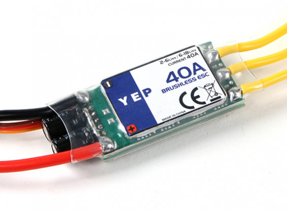
The ESC should be using regular PWM (not Oneshot125 etc) and be calibrated to the range 1000μs for zero throttle and 2000μs for full throttle. Better calibrate the ESC (set the throttle to full before powering up the ESC, then to zero after powering it up) before using.The rating of the ESC depends on the load on which it is operated.Please ensure the BEC from ESC gives a 5V supply if it is used for powering up the arduino.
ESC <----> Arduino
- GND <----> GND
- Signal <----> Pin 5
- VCC <----> Pin Vin (optional)
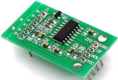
The load cell amplifier is a HX711.Either 5v or 3.3v can be used for the VCC.
The connections between the load cell and the amplifier will depend on the type of load cell you get. General info: https://learn.sparkfun.com/tutorials/load-cell-amplifier-hx711-breakout-hookup-guide
HX711 <----> Arduino
- GND <----> GND
- VCC <----> 3.3v
- DT <----> Pin 3
- SCK <----> Pin 4
The ADC is a ADS1115 which provides two 16-bit relative converters and communicates with the Arduino via I2C .
You can use one converter to measure voltage (with an appropriate voltage divider) and the other to measure the output of the current sensor (current reading).
The voltage divider will depend on the maximum voltage of the battery you intend to test with, and MUST ensure that the maximum voltage is under 5v.
Note that you can also use the analog pins of the arduino directly to measure voltage, but the resolution is only 10 bit (0-1023) which is not so good. For example a 3S lipo going from full charge (12.6v) to low charge (say 10.6v) is 2v change, so a 10:1 voltage divider sees 0.2v change, or 0.2/5 of the 0-1023 range which is only about 40 discrete steps, ie. a resolution of about 0.05v per step. Acceptable I suppose, but the situation is worse for the current sensor which deals in smaller ranges. If you only want to measure voltage, using a simple analogRead would probably be fine, but if you want to measure current and you have a ADS1115 you might as well also use it to measure the voltage, so the 16-bit ADC will give a voltage resolution of around 0.0008v.
General info: http://henrysbench.capnfatz.com/henrys-bench/arduino-voltage-measurements/arduino-ads1115-module-getting-started-tutorial
ADS1115 <----> Arduino
- GND <----> GND
- VDD <----> 5v
- SDA <----> Pin A4
- SCL <----> Pin A5
- A0 <----> GND
- A1 <----> V (voltage sensing)
- A2 <----> I (current sensing)
- A3 <----> GND

The current sensor used here is INA 169. This particular sensor is rated to 90A maximum. The OUT (I) pin of this sensor will give an analog voltage (0-3.3v) corresponding to the current flowing through the sense terminals. This analog voltage is given to the ADC to get a digital value. You could use regular analogRead of the Arduino instead, but most likely the voltage range will be too small to get good readings. The sensor uses a precision shunt resistor to measure the current flow ,the voltage drop across the shunt resistor is amplified differentially through a op-amp to give a analog voltage output. Voltage sense is accomplished by scaling to 3.3v ADC range by a precision resistor divider. The current limit coincides with the maximum power rating of the shunt resitors. The sensor is self powered and does not need an external 5v supply.
General info: https://cdn.sparkfun.com/datasheets/Sensors/Current/DC%20Voltage%20and%20Current%20Sense%20PCB%20with%20Analog%20Output.pdf
INA169 w/ voltage sense <----> Arduino
- GND <----> GND
- V <----> A1 of ADS1115
- I <----> A2 of ADS1115
- Sense terminals should bridge a break in the main power line

IR sensor module is used to detect the speed of rotating body. It transmits infrared rays which reflects back to IR receiver and then the module generates an output pulse which is sent to the arduino. By counting the number of pulses (rising edges) and the time taken,knowing the number of blades of the motor we can calculate the number of revolutions per minute.
IR <----> Arduino
- GND <----> GND
- VCC <----> 5v
- OUT <----> Pin 2

Make sure you get a buzzer that is a 'continuous' one, that is, powering it with 5v is all that is necessary to make it sound (some buzzers require the input voltage to be pulsed on and off to make a sound).
Buzzer <----> Arduino
- GND <----> GND
- VCC (+) <----> Pin 7
Keep in mind that there is potential for injury here. Make sure your test stand is solidly constructed and cannot wobble around or tip over when the motor is unleashed. You might want to also have a screen of some kind between you and the motor just in case a prop breaks and the blade flies out.
After making the connections as above, upload the sketch to your Arduino.
Run the python script and position the thrust stand before taring the load cell,after some delay the python shell displays the sensor readings and measurements with a specified time interval.
If you encountered an keyboard interrupt, pls make sure the csv file is not opened or modified.
Calibration for each sensor should be done prior to ensure accurate readings. Measure the readings for zero error and take appropriate correction factor. Taring of load cell can be done in the initial stages of the python script execution. calibration sketch
Below files are generated using random loads and different motor prop combinations.