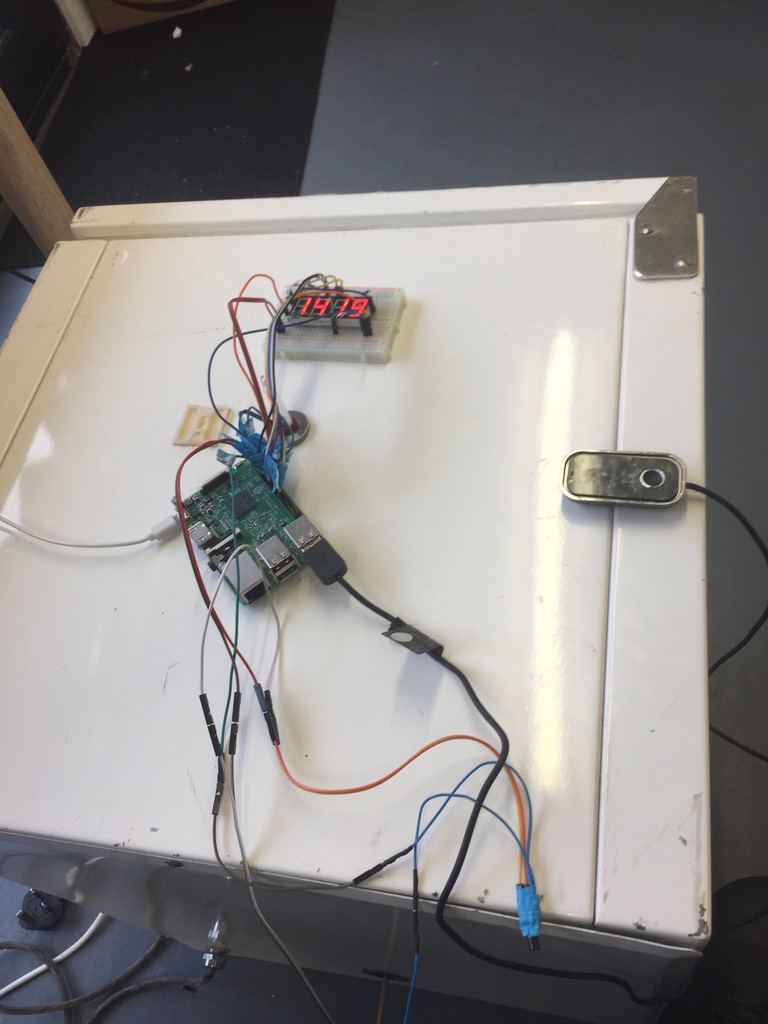
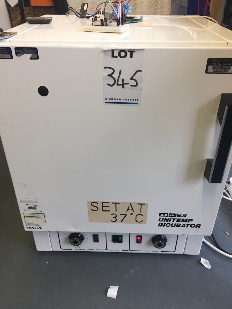
I have come across a lot of old incubators that use old mercury thermometers. In general they are robust and if they still work it is just useful to be able to digitally record and monitor the temperature.
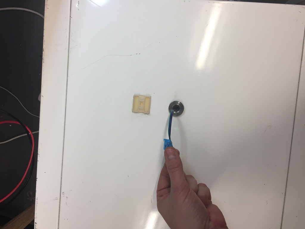
These are usually found left over from universities or from second hand auctions. The ones that use mercury thermometers are ideal from this project as they have a hole already in the top of the housing.
You need:
- Raspberry pi 3,4 or Zero (or another model is fine as long as you have wifi).
- DHT 11 sensor
- Raspicam
- A 240V relay
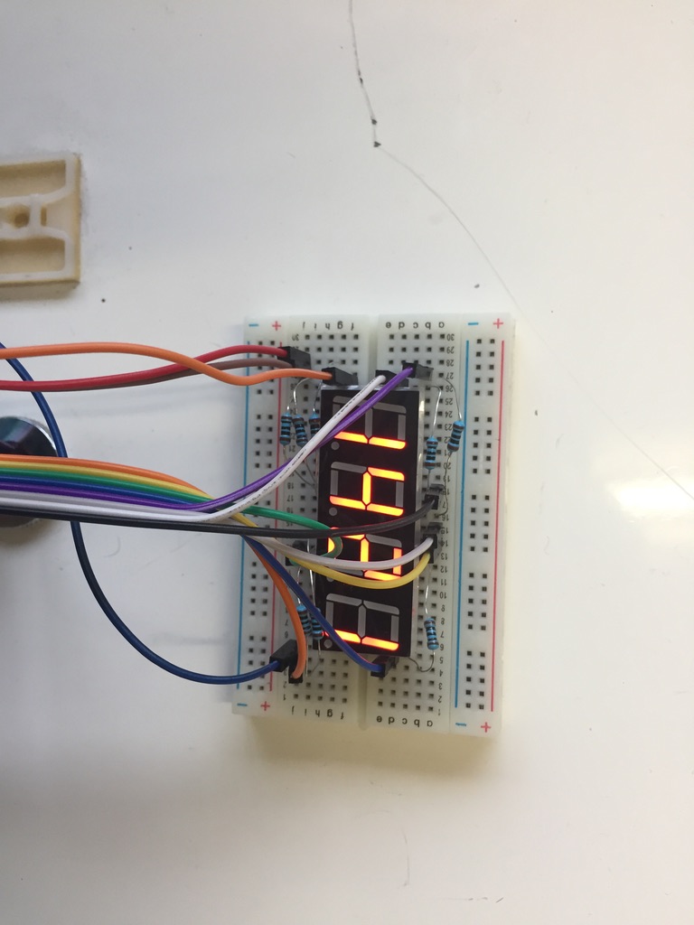
- An LED display
- (optional) usb webcamera
Where to get them If you are in the UK you can be lazy and use this amazon shopping cart but I find RS Components to be the fastest and cheapest (free next day delivery and no minimum order). They stock older raspi versions (3+) which are perfect for this project as well as almost infinite amount of sensors and other electronics.
This project will require controlling GPIO pins on the Raspberry Pi. The layout of these pins is almost impossible to remember or understand. I recommend this outstanding resource: Pi GPIO layout
I will refer exclusively to the actual pin numbers on the device: 1-40
Pin Layout
Running the Relay
Using a 5V relay like this requires three pins: 5V, GND, comm (send).
Pin order
| Relay | Raspi |
|---|---|
| Vcc | |
| GND | |
| Com |
Running the LED display
Basically just this blog.
Creating a timelapse
Running the DHT 11
DHT11 is great because it is a 3 pin device, just like a relay you have a 5V, GND and comm (receive).
| DHT11 | Raspi |
|---|---|
| Vcc | |
| GND | |
| Com |
Camera and light
I used a raspicam but you can also use a webcam if you prefer.
Record and send to the web
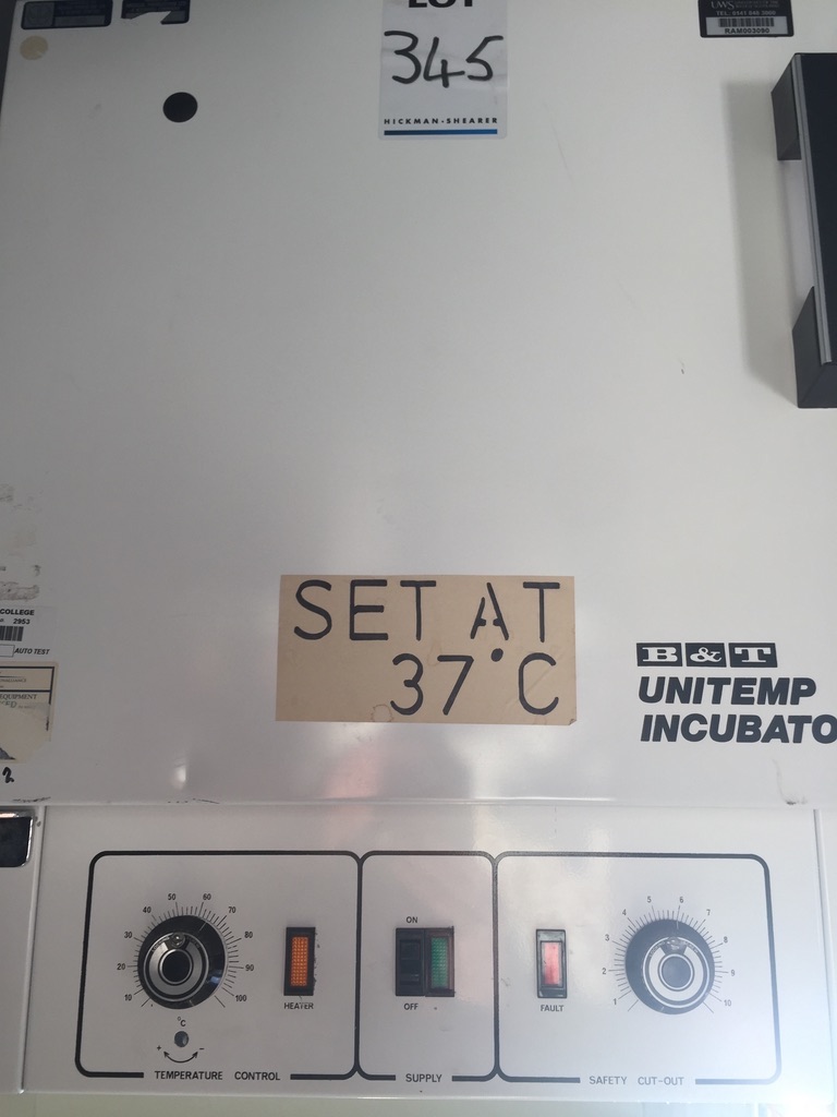
I will talk about how I assembled my system but it is likely going to be different for you depending on what type of incubator you found. Hopefully this is useful! My incubator was a B & T UniTemp incubator.
The B & T UniTemp Incubator: How it Works
It was originally designed to have a temperature set by potentiometer and also has a few safety features. It has an additional backup adjustable cutout if the temeperature goes above a set threshold. It also has a built in thermal fuse which will break if the temperature goes above a particular temperature. It also has a hole in the top designed for a thermometer to go inside.
I bought two of these units straight from auction and one worked and one didn't. This is the one that didn't :)
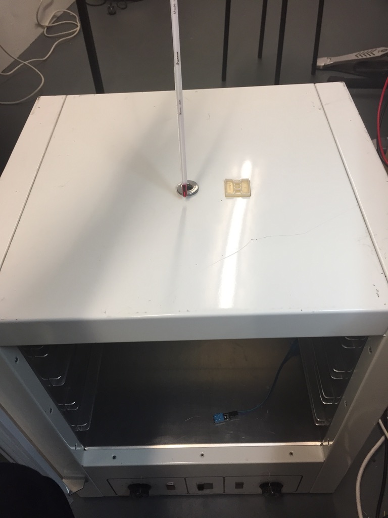
The top of the unit has the thermometer sticking out and the original design involves setting your temperature using the controls and checking if the temperature is correct by manually pulling the thermometer out.

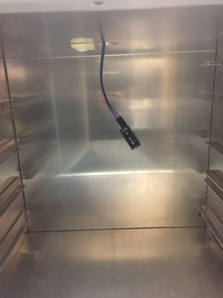
The thermometer just sits in the middle of the incubator.
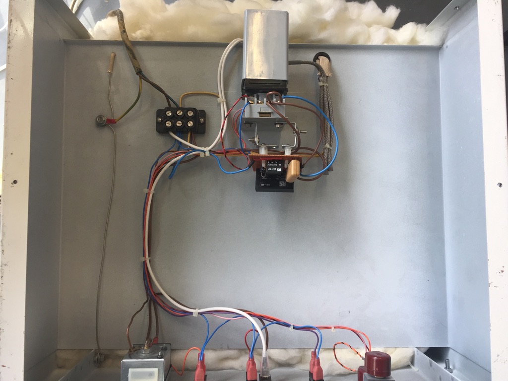
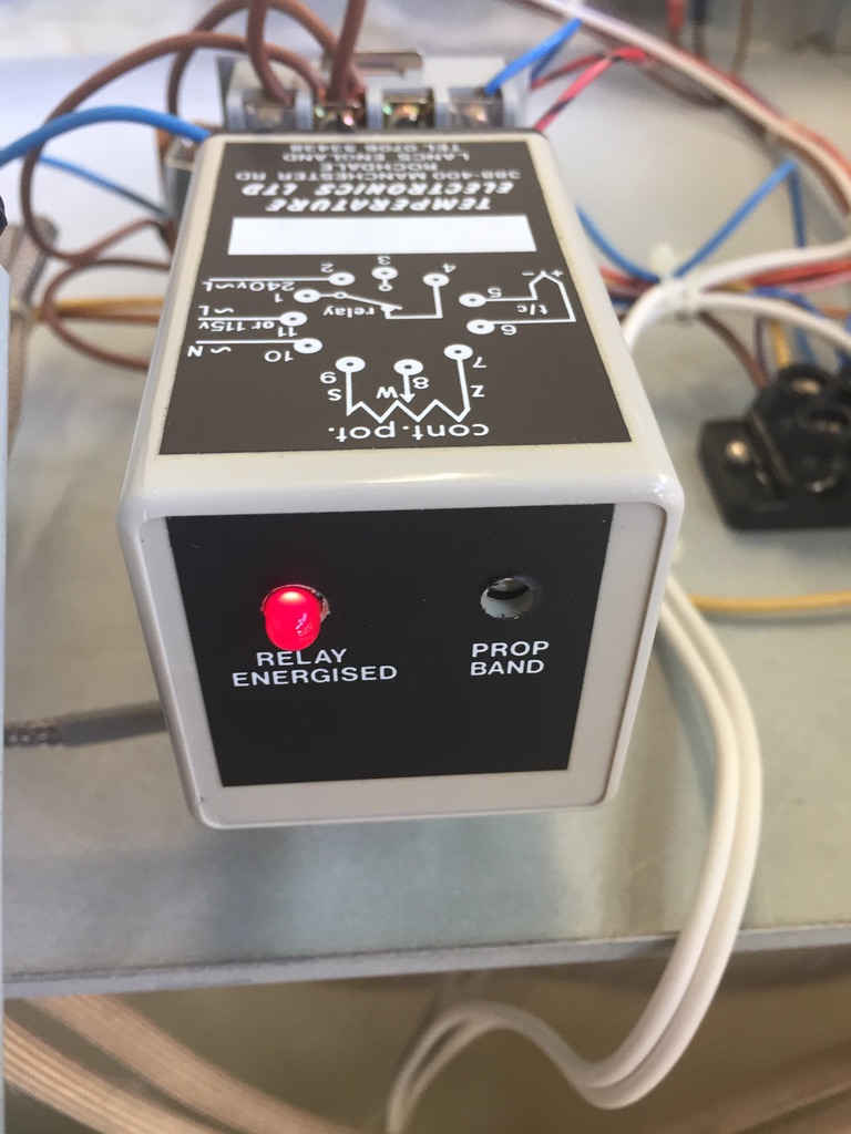
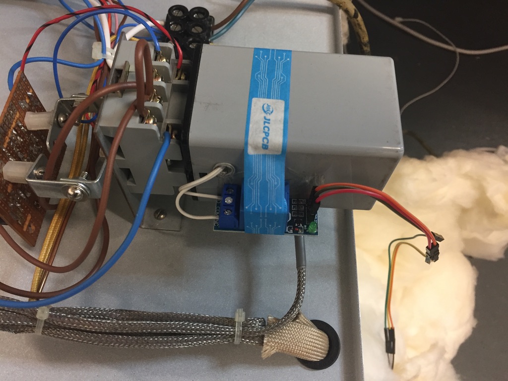
The internal layout basically takes mains voltage (240V) and the potentiometers on the front of the instrument are variable resistors determining how much current reaches the internal heater. The box at the back of the instument contains the relay. The relay switches the current on or off and controls wether the heater on or off. I wanted to remove this device and use an external relay that I could control with a raspberry pi.
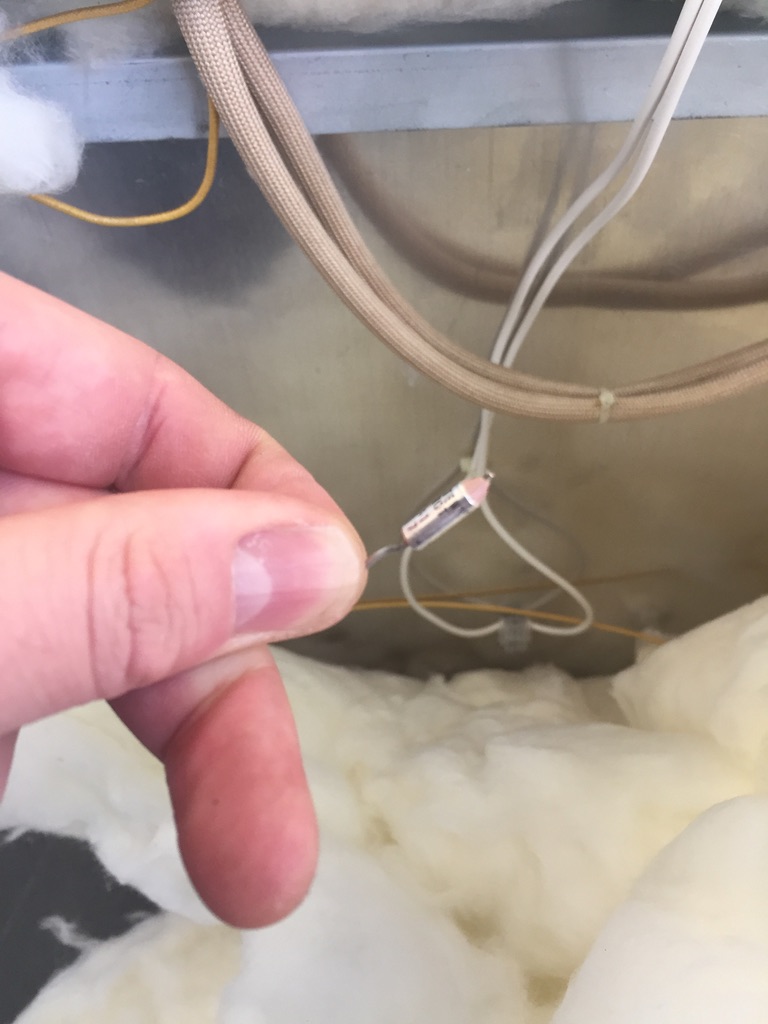
The Thermal fuse. In my case this had blown and needed replacing. I chose one with a 13 amp current limit and 120 Celcius melt point.
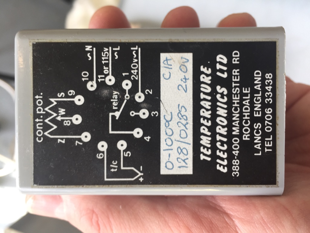
The internal relay box was not quite working correctly.
The relay unit was an additional source of error. The relay would not be effectively switched on and would just come on/off with a rate determined by the vaiable resistor(s) on the unit. I tried to troubleshoot this and in the end decided that it was a hassle and that is why I replaced with an externally controlled 5V relay.
Removing Relay and replacing with an Externally controlled Unit
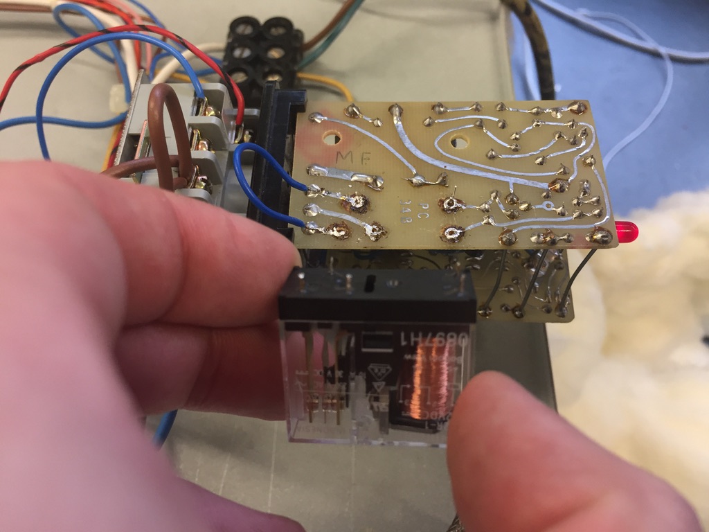
The relay housing needs to be opened and the relay identified, removed and replaced.
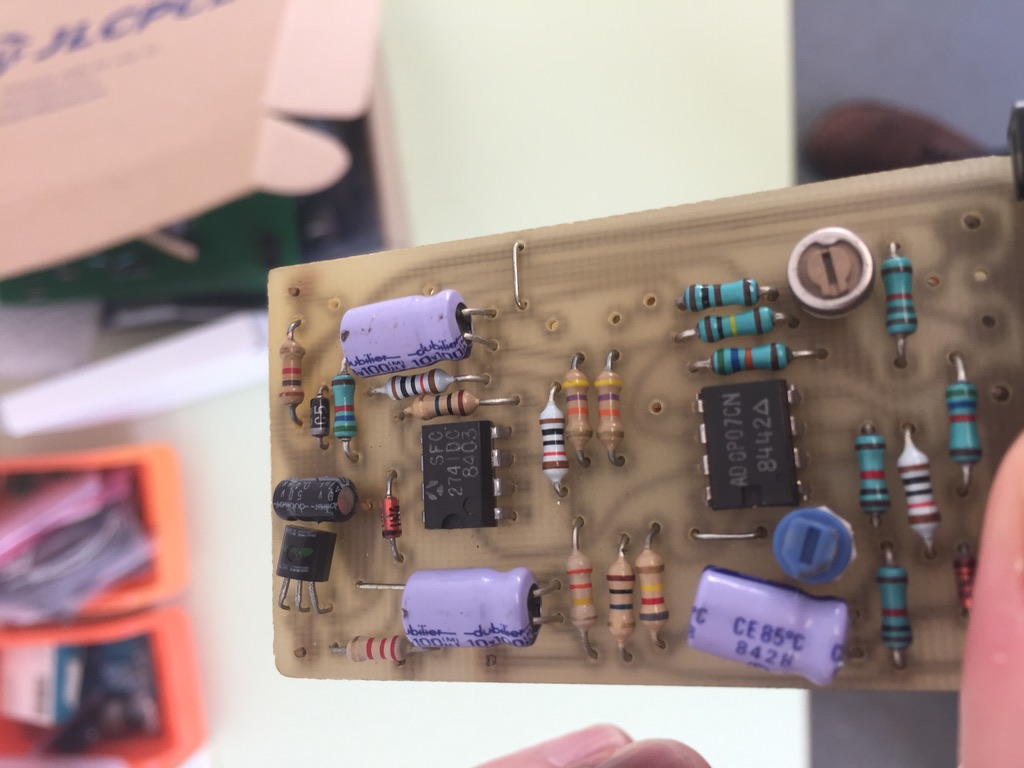
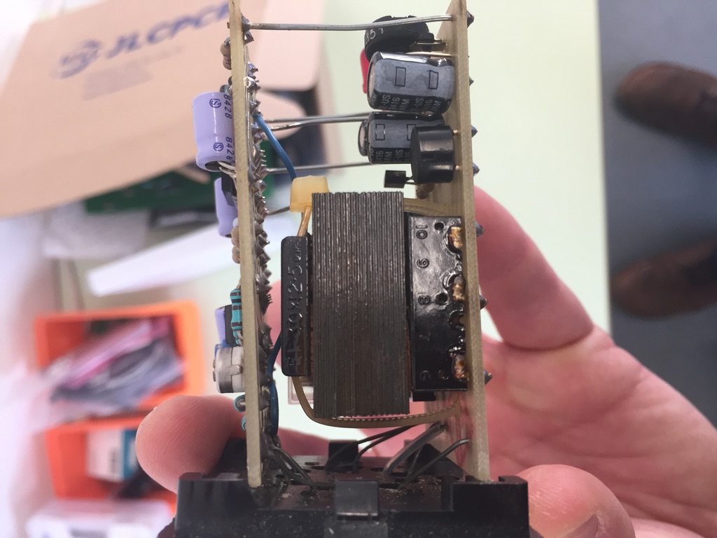
The top of the relay housing provides the control system that switches the relay on or off.. One of these is misbeahving but despite a long check I could not find the issue(s?).. In general if you are testing items like resisters or capacitors you just need a multimeter. The potentiometers (items with a little screm on top) are easy as well. Just measure resistance and then turn the screw. The resistance should change. If it doesn't then there is an issue. More complex devices like transistors (the three legged devices on the board) are harder. But in general there should be an extremely high resistance between two terminals. If not the unit could be blown. The microcontrollers (8 legged devies that are rectangular) are even harder. You really need to get a specification sheet. I could not find one for these since the unit is veeeery old. That meant I kind of hit a wall.
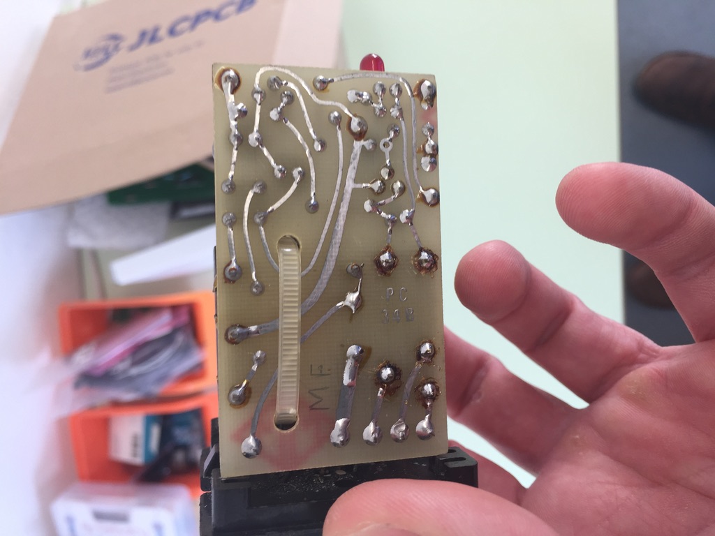
Bottom PCB board is an elegant home made PCB board! Beautiful!
The big black block looking thing is a transformer. It takes the input 240V AC and steps down to 12V DC. That then is used to control the relay. This is acutally easy to test. You can measure the resistance between the input terminals and compare to the output terminals and the ratio should be the same as 240V:12V.
You need to remove this relay. You will need a soldering iron and also a solder vacumm ( a small tube that you can press a button and it sucks up hot solder).
Once the relay is removed place the external relay in it's place with some wires.
Connecting Electronics to Raspi
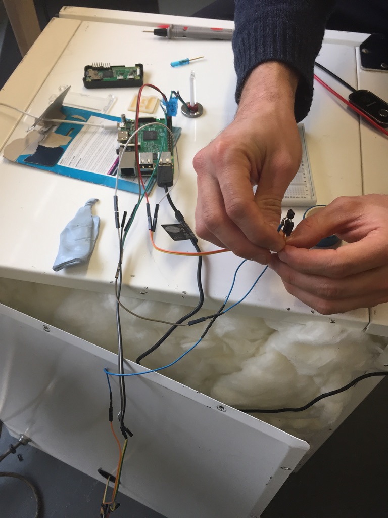
The device wiring needs to be completed. Connecting the relay, DHT11, LED display to the raspberry pi.
The relay needs to be controlled by three pins, 5V power supply, Ground, and a GPIO control pin.
The DHT11 fits neatly through the incubator hole.
It sits very nicely in the middle of the incubator just like the thermometer!
This is a small nightmare. I copied: this blog.
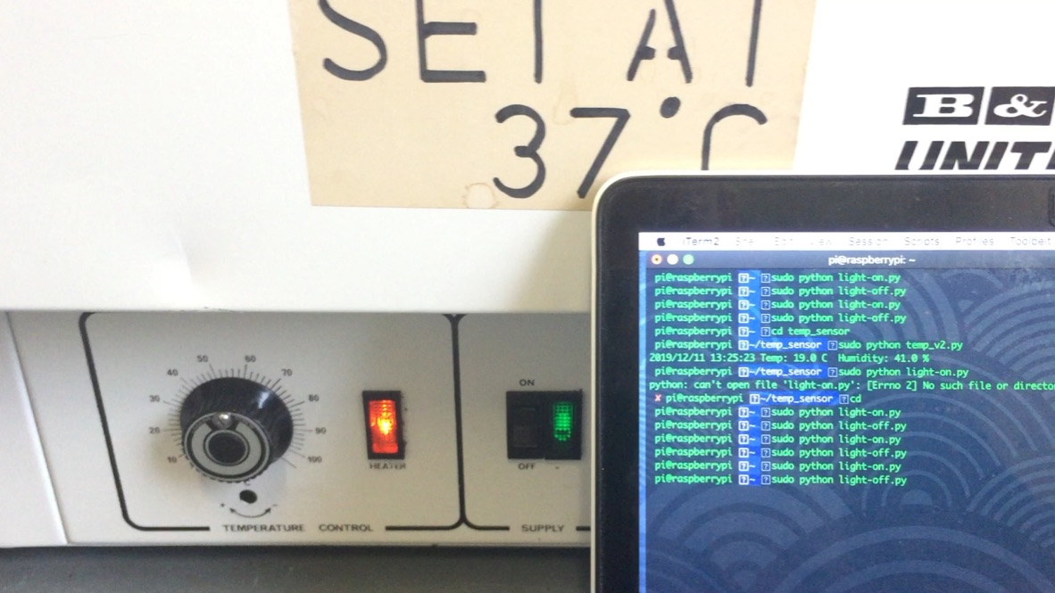
The device could be controlled from the command line and turns the relay on/off.
The finished unit will take a picture every 5 mins, post it to a webpage, maitain a fixed temperature and display the internal temperature on an LED. Quite useful!
Please tell me if you have any issues, ideas or improvements.!
Some really cool projects already exist.
The Pelling lab actually built an incubator from scratch! It is even equiped with CO2 for mamalian cell culture. Really good idea, they just use an old strofoam box as the incubator housing!
A group built an orbital shaker which would fit nicely into an incubator
Dan Chen's Lab have built a quick and easy design for a single tube mixer, could be ideal for minipreps..
